Table of Contents
Advertisement
Quick Links
Advertisement
Table of Contents

Related Manuals for LEYBOLD Leycon CMOVE 1250


Summary of Contents for LEYBOLD Leycon CMOVE 1250
- Page 1 LEYCON User manual 17200234_002_C1/2016 Controller CMOVE 1250 Part number 230 200...
- Page 2 Leybold. Offenders are liable to pay damages. The use of trade names, brand names, trademarks, etc. in this user manual does not entitle third parties to consider these names to be unprotected and to use them freely.
-
Page 3: Table Of Contents
Automatic Reset Function ..............45 5.2.6 Operating Mode ..................47 5.2.7 Valve ..................... 48 5.2.8 Control Mode ..................49 5.2.9 Pressure Sensor ................... 50 5.2.10 Digital Inputs ..................51 5.2.11 Digital Outputs..................52 5.2.12 Analog Inputs/Outputs ................ 55 602494EA.DOCX 17200234_002_C1/2016 - © Leybold 3/102... - Page 4 Spare parts and accessories ............93 Appendix ................... 95 12.1 Implemented Pressure Sensors ................ 95 12.2 Troubleshooting ....................96 12.3 Conversion Tables .................... 97 12.4 Literature ......................98 12.5 Declaration of incorporation ................99 4/102 17200234_002_C1/2016 - © Leybold 602494EA.DOCX...
-
Page 5: Description Of Product
Bonner Str. 498, D-50968 Köln, Germany Figure 1-1 PN: Part number SN: Fabrication number In all communications with Leybold, please specify the information on the product nameplate Validity oft the Oparationg Manual This operating manual applies to products with part number 230 200. -
Page 6: Technical Data
Display LCD 64×128 Pixel Measurement units (selectable) Pressure mbar, Torr, Pa, mV Flow mbar l/s, Torr l/s, Pa l/s, %, mV Valid for sensor setting 0 … +10 V lin and output AO 2. 6/102 17200234_002_C1/2016 - © Leybold 602494EA.DOCX... - Page 7 «5.2.10 Digital Inputs», on operation see chapter «5.4 Operation Via Inputs and Outputs» For information on wiring see chapter «4.2.6 Analog Inputs/Outputs», on configuration see chapter «5.2.12 Analog Inputs/Output», on operation see chapter «5.4 Operation Via Inputs and Outputs» 602494EA.DOCX 17200234_002_C1/2016 - © Leybold 7/102...
- Page 8 «5.2.12 Analog Inputs/Output», on operation see chapter «5.4 Operation Via Inputs and Outputs». The 0 … 10 VDC analog output AO 2 can be used for control valves other than the MOVE 1250 and MOVE X. 8/102 17200234_002_C1/2016 - © Leybold 602494EA.DOCX...
- Page 9 (EN 60529) Weight [kg] 1.65 Table 1-1 For information on wiring see chapter «4.2.7 RS232 and RS485 Serial Interfaces», on configuration see chapter «5.2.13 Serial Interface», on operation see chapter «5.5 Operation Via Serial Interface» 602494EA.DOCX 17200234_002_C1/2016 - © Leybold 9/102...
- Page 10 TTR 21X Table 1-3 As the products of Leybold are subject to continual development, new pressure sensors may have been implemented in your CMOVE 1250 Controller. The 0-10 V lin setting can be used for controlling appropriate linear sensors other than the implemented ones, see chapter «5.2.9 Pressure Sensor».
- Page 11 0 … 10000 mV AO 2 Table 1-4 Dimensions [mm] 228.5 ø3.5 Figure 1-2 The 0 … +10 VDC analog output AO 2 can be used for control valves other than the MOVE 1250 and MOVE X. 602494EA.DOCX 17200234_002_C1/2016 - © Leybold 11/102...
-
Page 12: Scope Of Delivery
Improperly accomplished maintenance work may reduce the safety, lifetime and performance of the product and lead to refusal of warranty claims. Maintenance work not described in this user manual may only be carried out by the Leybold service staff or by specialists trained and authorized by Leybold. 12/102 17200234_002_C1/2016 - ©... -
Page 13: Safety
CAUTION Low risk Indicates a hazardous situation which, if not avoided, may result in minor or moderate injury. NOTICE Command Indicates a hazardous situation which, if not avoided, may result in property damage. 602494EA.DOCX 17200234_002_C1/2016 - © Leybold 13/102... -
Page 14: Purpose Of Use
• Either use, not explicitly mentioned as permitted use, applies as adverse use Obligations / area of responsibility 2.4.1 Manufacturer Leybold GmbH as manufacturer is responsible for supplying the product, with its user manual and original accessories, in a completely safe condition. 2.4.2 Operator The operator is the person in charge of the product. -
Page 15: Personnel Qualifications
Disconnecting device The disconnecting device must be readily identifiable and easily reached by the user. To disconnect the controller from mains, you must unplug the mains cable. Disconnecting device acc. to EN 61010-1 Figure 2-2 602494EA.DOCX 17200234_002_C1/2016 - © Leybold 15/102... -
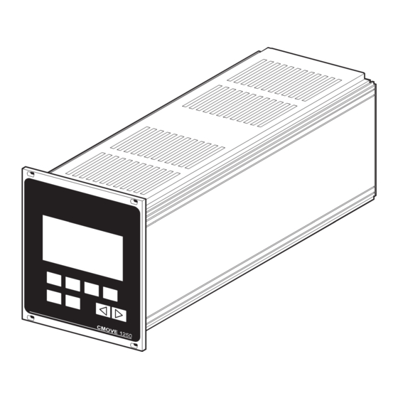
Page 16: Design And Function
Serial interface setting or returning to the previous Main switch display k Mains power connector d Edit key, for modifying settings Valve connector e Arrow keys, for modifying values m Connectors for pressure sensors 16/102 17200234_002_C1/2016 - © Leybold 602494EA.DOCX... -
Page 17: Operating Modes
The control valve regulates the gas inlet of the vacuum system. The valve plate moves in closing direction when the pressure in the vacuum system rises. Vacuum CMOVE 1250 Gas inlet system Valve Pressure sensor Vacuum pump Figure 3-2 602494EA.DOCX 17200234_002_C1/2016 - © Leybold 17/102... - Page 18 The gain (Kp), reset time (Tn), and derivative time (Tv) of the PID (proportional/integral/derivative) controller type are user-definable. The PID controller is used when good control to a setpoint (nominal value) combined with a fast response is required. 18/102 17200234_002_C1/2016 - © Leybold 602494EA.DOCX...
- Page 19 Δp of 1 bar. The flow rate curve depends on the control valve used. The curves shown in the following diagrams correspond to a mean value for air at a pressure difference Δp of 1 bar. 602494EA.DOCX 17200234_002_C1/2016 - © Leybold 19/102...
- Page 20 Example of a flow rate curve (mean values 500 sccm F.S) at a pressure difference Δp = 1 bar. Gas flow [sccm] Control valve open Control valve closed Current (solenoid coil) [mA] Figure 3-6 20/102 17200234_002_C1/2016 - © Leybold 602494EA.DOCX...
-
Page 21: Installation
• Store the original packaging material. It may be useful if products must be returned. WARNING Damaged product Putting a damaged product into operation can be extremely hazardous. In case of visible damage make sure the product is not put into operation. 602494EA.DOCX 17200234_002_C1/2016 - © Leybold 21/102... -
Page 22: Installation Into The System
Take appropriate measures for the rack to meet the specifications of the protection category. Slide the CMOVE 1250 into a 19" rack chassis and fasten it with the supplied four collar screws and plastic sleeves. Height 3 U Figure 4-1 22/102 17200234_002_C1/2016 - © Leybold 602494EA.DOCX... -
Page 23: Mains Power Connection
The socket must befuse-protected with 10 A Figure 4-2 The mains voltage should be supplied and turned on via a central power distributor because the main switch of the CMOVE 1250 cannot be reached from the front. 602494EA.DOCX 17200234_002_C1/2016 - © Leybold 23/102... -
Page 24: Valve Connection
Connect the MOVE 1250 Control Valve to the «X9 valve» receptacle (MOVE 1250 and connection cable see chapter «11 Spare parts and accessories»). Figure 4-3 X9 VALVE Signal (Serial Interface) ANOUT+ 3 (not used) ANOUT- 4 (not used) 24VDC Table 4-1 24/102 17200234_002_C1/2016 - © Leybold 602494EA.DOCX... - Page 25 Connect the MOVE X Control Valve to the «X9 valve» receptacle (MOVE X and connection cable see chapter «11 Spare parts and accessories»). Figure 4-4 X9 VALVE Signal 1 (not used) 2 (not used) ANOUT+ ANOUT- 24VDC 5 (not used) Table 4-2 602494EA.DOCX 17200234_002_C1/2016 - © Leybold 25/102...
-
Page 26: Pressure Sensor
Pressure sensors specified for a max. operating pressure (e.g. ITR 100) will start operation only after the signal "Emission ON" is applied to the digital input DI 7 of the CMOVE 1250 (see chapter «5.4 Operation Via Inputs and Outputs»). 26/102 17200234_002_C1/2016 - © Leybold 602494EA.DOCX... - Page 27 Pressure sensors specified for a max. operating pressure (e.g. PTR 237) will start operation only after the signal "Emission ON" is applied to the digital input DI 7 of the CMOVE 1250 (see chapter «5.4 Operation Via Inputs and Outputs»). 602494EA.DOCX 17200234_002_C1/2016 - © Leybold 27/102...
-
Page 28: Digital Inputs/Outputs
• Run the signal lines physically separated from the feeder and control lines. Wire the enclosed 25-pin female D-Sub cable connector in accordance with the pin assignment, plug it in and secure it with the screws. Within scope of delivery Figure 4-6 28/102 17200234_002_C1/2016 - © Leybold 602494EA.DOCX... - Page 29 +24 VDC/2.5 mA DI 7 Emission ON (HV ON) +24 VDC/2.5 mA DI 8 Degas ON +24 VDC/2.5 mA DI GND Ground digital inputs 0 VDC DI GND Ground digital inputs 0 VDC Table 4-6 602494EA.DOCX 17200234_002_C1/2016 - © Leybold 29/102...
- Page 30 +24 VDC/100 mA DO GND Ground digital outputs 0 VDC DO GND Ground digital outputs 0 VDC DO +24VDC Supply digital outputs +24 VDC Not connected Not connected Not connected Not connected Table 4-7 30/102 17200234_002_C1/2016 - © Leybold 602494EA.DOCX...
-
Page 31: Analog Inputs/Outputs
Pin assignment analog inputs Designation Description Signal AI 1 Pressure setpoint (nominal value) 0 … +10 VDC AI 2 Flow setpoint (nominal value) 0 … +10 VDC AI 3 Not used AI 4 Not used Figure 4-8 602494EA.DOCX 17200234_002_C1/2016 - © Leybold 31/102... - Page 32 Signal Ground analog inputs/outputs 0 VDC 9 … 15 Table 4-10 The 0 … +10 VDC analog output AO 2 can be used for control valves other than the MOVE 1250 and MOVE X. 32/102 17200234_002_C1/2016 - © Leybold 602494EA.DOCX...
-
Page 33: Rs232 And Rs485 Serial Interfaces
• Run the interface line physically separated from the supply and control lines. Wire a 9-pin male D-Sub cable connector in accordance with the pin assignment, plug it in and secure it with the screws. Figure 4-10 602494EA.DOCX 17200234_002_C1/2016 - © Leybold 33/102... - Page 34 Not to be used Not to be used SIO GND Not to be used Bus terminator (–) (connect with pin 7) TXD/RXD (–) TXD/RXD (+) Bus terminator (+) (connect with pin 8) Table 4-12 34/102 17200234_002_C1/2016 - © Leybold 602494EA.DOCX...
-
Page 35: Operation
«1.4 Technical Data» are met. Make sure that the main switch on the rear of the CMOVE 1250 is in the ON position. Figure 5-1 Turn the CMOVE 1250 on via the switched power distributor. 602494EA.DOCX 17200234_002_C1/2016 - © Leybold 35/102... - Page 36 Pressure • the CMOVE 1250 starts operating in >1.00E+03 the Pressure control mode and with the Act : mbar default parameter settings after 3 Nom : 1.33E+01 mbar seconds. PARAM SOURCE CONTROL Figure 5-4 36/102 17200234_002_C1/2016 - © Leybold 602494EA.DOCX...
- Page 37 Turn the CMOVE 1250 OFF via the switched power distributor. The «POWER OFF ALARM» is displayed for a few seconds. POWER OFF ALARM The control valve is closed within 3 seconds! command edit Figure 5-5 602494EA.DOCX 17200234_002_C1/2016 - © Leybold 37/102...
-
Page 38: Configuration
See chapter «5.2.9 Pressure Sensor» Digital inputs See chapter «5.2.10 Digital Inputs» Digital outputs See chapter «5.2.11 Digital Outputs» Analog inputs/outputs See chapter «5.2.12 Analog Inputs/Output» Serial interface See chapter «5.2.13 Serial Interface» Table 5-1 38/102 17200234_002_C1/2016 - © Leybold 602494EA.DOCX... - Page 39 Operating level (Pressure or Flow mode). VALVE SENSOR GEN. Pressure mode Pressure >1.00E+03 Act : mbar Nom : 1.33E+01 mbar PARAM SOURCE CONTROL Flow mode Flow close mbarl/s Press. :>1.00E+03 mbar PARAM OPEN CLOSE 602494EA.DOCX 17200234_002_C1/2016 - © Leybold 39/102...
- Page 40 DI 6: Pressure mode DO 6: ready AO 2: Valve Signal DI 7: Emission ON DO 7: Emission ON AO 3: Valve position DI 8: Degas ON DO 8: Sensor status AO 4: +10V REF DI1-4 DO1-4 40/102 17200234_002_C1/2016 - © Leybold 602494EA.DOCX...
-
Page 41: Lcd Contrast
LCD contrast between Measure : mbar 0 … 99 (0 = light, 99 = dark). Language : english Autoboot : on Autoreset : off to save the new setting and return to the «Configuration» display. 602494EA.DOCX 17200234_002_C1/2016 - © Leybold 41/102... -
Page 42: Measurement Unit Of The Pressure
LCD-Contrast : 30 to select the measurement unit of the Measure mbar pressure: mbar, Pascal, Torr Language : english Autoboot : on Autoreset : off to save the new setting and return to the «Configuration» display. 42/102 17200234_002_C1/2016 - © Leybold 602494EA.DOCX... -
Page 43: Language
General settings Press LCD-Contrast : 30 to select the language. Measure : mbar deutsch, english Language english Autoboot : on Autoreset : off to save the new setting and return to the «Configuration» display. command 602494EA.DOCX 17200234_002_C1/2016 - © Leybold 43/102... -
Page 44: Automatic Booting Function
CMOVE 1250 again. Configuration Pressure Mode : Pressure >1.00E+03 Valve : MOVE1250STD Act : mbar Sensor: CTR1000T Nom. I: 1.33E+01 mbar Nom : 1.33E+01 mbar VALVE SENSOR GEN. PARAM SOURCE CONTROL 44/102 17200234_002_C1/2016 - © Leybold 602494EA.DOCX... -
Page 45: Automatic Reset Function
This setting determines how the CMOVE 1250 will behave in the following cases: • The operating mode was changed from Pressure to Flow and then back to Pressure • Signal «Externally CLOSE» (DI 3) active • Signal «Externally OPEN» (DI 4) active 602494EA.DOCX 17200234_002_C1/2016 - © Leybold 45/102... - Page 46 LCD-Contrast : 30 to set the automatic reset function to on Measure : mbar or off. Language : english Autoboot : on Autoreset to save the new setting and return to the «Configuration» display. 46/102 17200234_002_C1/2016 - © Leybold 602494EA.DOCX...
-
Page 47: Operating Mode
(setpoint) and return to the Operating level. Pressure control mode (Pressure) Pressure >1.00E+03 Act : mbar Nom : 1.33E+01 mbar PARAM SOURCE CONTROL Gas flow adjustment mode (Flow) Flow close mbarl/s Press. :>1.00E+03 mbar PARAM OPEN CLOSE 602494EA.DOCX 17200234_002_C1/2016 - © Leybold 47/102... -
Page 48: Valve
MOVE 1250, MOVE X and Type MOVE1250 Char. : STD AO 2. to save the new setting and return to the SAVE «Configuration» display. to return to the «Configuration» display SAVE without saving the new setting. 48/102 17200234_002_C1/2016 - © Leybold 602494EA.DOCX... -
Page 49: Control Mode
Type : MOVE1250 to select among STD and INV. Char. SAVE to save the new setting and return to the «Configuration» display. SAVE to return to the «Configuration» display without saving the new setting. 602494EA.DOCX 17200234_002_C1/2016 - © Leybold 49/102... -
Page 50: Pressure Sensor
= logarithmic pressure sensor SAVE to edit the sensor type setting. SAVE to save the new setting and return to the «Configuration» display. to return to the «Configuration» display without saving the new setting. 50/102 17200234_002_C1/2016 - © Leybold 602494EA.DOCX... -
Page 51: Digital Inputs
The «Inputs/Outputs» display shows the following Inputs/Outputs menu: «DI» Digital inputs «DO» Digital outputs «AI/AO» Analog inputs/outputs «SERIAL» Serial interfaces AI/AO SERIAL to get to the «Digital Inputs» display. to return to the «Configuration» display. 602494EA.DOCX 17200234_002_C1/2016 - © Leybold 51/102... -
Page 52: Digital Outputs
(setpoint) with source Mode : Pressure Valve : MOVE1250STD (I = internal, E = external). Press Sensor : CTR1000T Nom. I : 1.33E+01 mbar to get to the «Inputs/Outputs» display. VALVE SENSOR GEN. 52/102 17200234_002_C1/2016 - © Leybold 602494EA.DOCX... - Page 53 DO 5: Sensor error DO 6: ready to get to the DO 7: Emission ON «Digital Outputs 1 to 4» display. DO 8: Sensor status DO1-4 to return to the «Inputs/Outputs» display. DO1-4 command 602494EA.DOCX 17200234_002_C1/2016 - © Leybold 53/102...
- Page 54 DO 2: Valve open to get to the DO 3: in position «Digital Outputs 5 to 8» display. DO 4: Valve error to get to the «DO 3 Deviation» display. to return to the DO5-8 «Inputs/Outputs» display. 54/102 17200234_002_C1/2016 - © Leybold 602494EA.DOCX...
-
Page 55: Analog Inputs/Outputs
Mode : Pressure Valve : MOVE1250STD (setpoint) with source (I = internal, E = ex-ternal). Sensor : CTR1000T Press. Nom. I : 1.33E+01 mbar VALVE SENSOR GEN. to get to the «Inputs/Outputs» display. 602494EA.DOCX 17200234_002_C1/2016 - © Leybold 55/102... - Page 56 1 to 4. Press. AO 1: Signal Sensor AO 2: Valve Signal to get to the «Analog Inputs» display. AO 3: Valve position AO 4: +10V REF to return to the «Inputs/Outputs» display. 56/102 17200234_002_C1/2016 - © Leybold 602494EA.DOCX...
-
Page 57: Serial Interface
The «Inputs/Outputs» display shows the following Inputs/Outputs menu: «DI» Digital inputs «DO» Digital outputs «AI/AO» Analog inputs/outputs «SERIAL» Serial interfaces AI/AO SERIAL to get to the «Interface» display. to return to the «Configuration» display. SERIAL 602494EA.DOCX 17200234_002_C1/2016 - © Leybold 57/102... - Page 58 RS 485 (PRI-Status: Off)), RS 232 (PRI-Status: On), RS 485 (PRI-Status: Off)), or ----- (operation without interface); the interface parameters will be displayed. to save the new setting and return to the «Inputs/Outputs» display. 58/102 17200234_002_C1/2016 - © Leybold 602494EA.DOCX...
-
Page 59: Operation Via Keys
Changing from the Pressure to the Flow mode: Press to get to the «Configuration» display. to edit the operating mode setting. to select among Pressure and Flow. to return to the Operating level. See section «5.2.6 Operating Mode» for more details. 602494EA.DOCX 17200234_002_C1/2016 - © Leybold 59/102... -
Page 60: Pressure Control
The «Pressure» display shows the actual value Pressure (pressure reading) and the nominal value (setpoint). Press. >1.00E+03 Act : mbar to get to the Nom : 1.33E+01 mbar «Parameter Pressure» display. PARAM SOURCE CONTROL PARAM 60/102 17200234_002_C1/2016 - © Leybold 602494EA.DOCX... - Page 61 SAVE to edit the «Min» setting. to edit the «Max» setting. SAVE to save the current setting and return to the «Pressure» display. to return to the «Pressure» display without saving the new settings. 602494EA.DOCX 17200234_002_C1/2016 - © Leybold 61/102...
- Page 62 Pressure mode. Press Source: internal to modify the source setting. SAVE to save the new setting and return to the «Pressure» display. to return to the «Pressure» display. SAVE 62/102 17200234_002_C1/2016 - © Leybold 602494EA.DOCX...
- Page 63 Vacuum system Volume Pumping speed Vacuum pump Controller type Figure 5-7 Example: For a small vacuum system and a large vacuum pump, a value between 50 and 99 should be selected. 602494EA.DOCX 17200234_002_C1/2016 - © Leybold 63/102...
- Page 64 «Auto 1», the controller type is set back ---- to «PID».) SAVE to save the new setting and return to the «Pressure» display. SAVE to return to the «Pressure» display without saving the new setting. 64/102 17200234_002_C1/2016 - © Leybold 602494EA.DOCX...
- Page 65 CONTROL The «Controller type» display shows the currently Controller type selected controller type. Press. Type : to edit the controller type setting. 0.3 s 0.0 s SAVE to return to the «Pressure» display. SAVE 602494EA.DOCX 17200234_002_C1/2016 - © Leybold 65/102...
- Page 66 Tn. to adjust the derivative time Tv. to save the new setting and return to the «Pressure» display. to return to the «Pressure» display without saving the new setting. 66/102 17200234_002_C1/2016 - © Leybold 602494EA.DOCX...
-
Page 67: Gas Flow Adjustment
The Edit sign is displayed at the left or the flow value. Flow Press close mbarl/s to adjust the gas flow. Press. :>1.00E+03 mbar PARAM OPEN CLOSE Changing the unit see chapter «5.2.2 Measurement Unit of the Pressure» 602494EA.DOCX 17200234_002_C1/2016 - © Leybold 67/102... - Page 68 Source : internal the «Nom» softkey. SAVE to save the new setting and return to the «Flow» display. SAVE to return to the «Flow» display without saving the new setting. 68/102 17200234_002_C1/2016 - © Leybold 602494EA.DOCX...
- Page 69 Source internal external AI 2 SAVE to save the new setting and return to the «Flow» display. to return to the «Flow» display without SAVE saving the new setting. 602494EA.DOCX 17200234_002_C1/2016 - © Leybold 69/102...
- Page 70 If the «external AI 2» setpoint source was selected, Flow the «Flow» display shows the current gas flow and pressure reading. The nominal value (setpoint) cannot close mbarl/s be defined via the keys. Press. :>1.00E+03 mbar PARAM 70/102 17200234_002_C1/2016 - © Leybold 602494EA.DOCX...
-
Page 71: Operation Via Inputs And Outputs
[3] … [12]. DI 8 Degas ON The Degas function is activated if the connected pressure sensor offers this function. See instructions of the corresponding pressure sensor for further details [3] … [12]. 602494EA.DOCX 17200234_002_C1/2016 - © Leybold 71/102... - Page 72 Feeds the external nominal value (setpoint) for the Pressure mode. AI 2 Flow setpoint Feeds the external nominal value (setpoint) for the Flow mode. AI 3 Not used No function AI 4 Not used No function 72/102 17200234_002_C1/2016 - © Leybold 602494EA.DOCX...
- Page 73 The valve position signal of the MOVE 1250 can be directly processed via this output. AO 4 Reference voltage A constant +10 VDC voltage is available at this output. It can be used for feeding the analog inputs via a voltage divider. 602494EA.DOCX 17200234_002_C1/2016 - © Leybold 73/102...
-
Page 74: Operation Via Serial Interface
<CR><LF>. For data transmission to the CMOVE 1250, no blanks (SPACE) are admitted. All characters have to be upper case. Since there is no time limit between the individual signs, manual operation via the interface is possible. 74/102 17200234_002_C1/2016 - © Leybold 602494EA.DOCX... - Page 75 RS485 Serial Interfaces» • incorrect interface setting in the CMOVE 1250, see chapter «5.2.13 Serial Interface» • incorrect transmission parameter setting in the control system, see above • communication code not in ASCII characters 602494EA.DOCX 17200234_002_C1/2016 - © Leybold 75/102...
-
Page 76: Nominal Values (Setpoints)
FLO=00320 FLO=_ _320mV FLO=012.5 FLO=_12.5% Inquiry FLO? FLO=x.xxEsxx< Unit >l/s FLO=xxxxxmV FLO=xxx.x% Examples FLO? FLO=5.00E–06mbarl/s FLO? FLO=_ _320mV FLO? FLO=_12.5% Table 5-3 Only for MOVE 1250 Only for AO 2 Only for MOVE X 76/102 17200234_002_C1/2016 - © Leybold 602494EA.DOCX... - Page 77 FLO=4.99E-04Pal/s pressure unit) FLO=3.74E-06 FLO=3.74E-06Torrl/s Entry MOVE X FLO=000.0 FLO=_ _0.0% Entry AO2 FLO=00000 FLO=_ _ _ _0mV Table 5-4 In the display appears <closed>. Entry for mbar Entry for Pa Entry for Torr 602494EA.DOCX 17200234_002_C1/2016 - © Leybold 77/102...
-
Page 78: Operating Mode
MOD? MOD=PRESS Table 5-5 Gas flow adjustment Command Response Entry MOD=F MOD=FLOW MOD=FLOW Inquiry MOD? MOD=FLOW Table 5-6 Stopping the controller Command Response Entry MOD=W MOD=WAIT MOD=WAIT Inquiry MOD? MOD=WAIT Table 5-7 Alternative input 78/102 17200234_002_C1/2016 - © Leybold 602494EA.DOCX... -
Page 79: Key Interlock
Inquiry TAS? TAS=DISABLE Table 5-8 Enabling the keys Command Response Entry TAS=E TAS= ENABLE TAS= ENABLE Inquiry TAS? TAS= ENABLE Table 5-9 5.5.5 Firmware Version Command Response Inquiry VER? VER=3.1x Table 5-10 Alternative input 602494EA.DOCX 17200234_002_C1/2016 - © Leybold 79/102... -
Page 80: Actual Value
(ok) n = < underrange n = > overrange n = O n = E errr 5.5.7 Measurement Unit Command Response Inquiry UNT? UNT=mbar UNT? UNT=Pa UNT? UNT=Torr UNT? UNT=mV Table 5-12 80/102 17200234_002_C1/2016 - © Leybold 602494EA.DOCX... -
Page 81: Language
Command Response Meaning Inquiry VEN? VEN=xx Examples VEN? VEN=_0 MOVE 1250 STD VEN=80 MOVE 1250 INV VEN=_2 AO 2 STD VEN=82 AO 2 INV VEN=_3 MOVE X STD VEN=83 MOVE X INV Table 5-15 602494EA.DOCX 17200234_002_C1/2016 - © Leybold 81/102... - Page 82 Command Response Inquiry VAT? VAT=hhh Examples VAT? VAT=0BC Table 5-17 • Status Command Response VAS? VAS=hhh Inquiry Examples VAS? VAS=007 Table 5-18 • Version Command Response Inquiry VAV? VAV=xxx Examples VAV? VAV=115 Table 5-19 82/102 17200234_002_C1/2016 - © Leybold 602494EA.DOCX...
-
Page 83: Controller Parameters
For the PID (proportional/integral/derivative) controller, select RAS=0 and proceed to the Gain Kp, Reset time Tn and Derivative time Tv settings. Command Response Entry RAS=xx RAS=xx Example RAS=_0 RAS=_0 (PID) Inquiry RAS? RAS=_0 Table 5-21 602494EA.DOCX 17200234_002_C1/2016 - © Leybold 83/102... - Page 84 RSI=_ _30.3 Table 5-23 • Derivative time Tv Select a derivative time between 0.0 and 3600.0 s. Command Response Entry RSD=xxxx.x RSD=xxxx.x Example RSD=0021.2 RSD=_ _21.2 Inquiry RSD? RSD=xxxx.x Example RSD? RSD=_ _21.2 Table 5-24 84/102 17200234_002_C1/2016 - © Leybold 602494EA.DOCX...
-
Page 85: Digital Inputs/Outputs
DI 4 DI 3 DI 2 DI 1 Command Response Inquiry DIN? DIN=hh Example DIN? DIN=23 Table 5-26 Degas Command Response Inquiry DEG? DEG=x Example DEG? DEG=0 Deactivation DEG=0 DEG=0 Activation DEG=1 DEG=1 Table 5-27 602494EA.DOCX 17200234_002_C1/2016 - © Leybold 85/102... - Page 86 DO 8. DOT=08 → 00001000 Binary number Digital output DO 8 DO 7 DO 6 DO 5 DO 4 DO 3 DO 2 DO 1 Command Response Inquiry DOT? DOT=hh Example DOT? DOT=08 Table 5-29 86/102 17200234_002_C1/2016 - © Leybold 602494EA.DOCX...
-
Page 87: Maintenance
DANGER Electric shock Contact with live parts is extremely hazardous when liquids penetrate into the unit. Make sure no liquids penetrate into the equipment. Figure 6-1 602494EA.DOCX 17200234_002_C1/2016 - © Leybold 87/102... - Page 88 Unprofessionally handling compressed air can cause physical injury. Adhere to the relevant regulations and take the necessary precautions when handling compressed air. Leybold assumes no liability and the warranty becomes null and void if maintenance works are performed, which are not covered by this user manual. 88/102 17200234_002_C1/2016 - ©...
-
Page 89: Repairs
You will find the addresses of the service centers on the backside of the document. When contacting us, please always specify the fabrication number of the valve; see chapter «1.2 Identification of product». 602494EA.DOCX 17200234_002_C1/2016 - © Leybold 89/102... -
Page 90: Dismounting And Storage
Withdraw the CMOVE 1250 from the 19" rack chassis. Storage NOTICE Wrong storage Inappropriate storage (static electricity, humidity etc.) can damage electronic components. Store product in antistatic bag or container. Observe the corresponding specifications in chapter «1.4 Technical Data». 90/102 17200234_002_C1/2016 - © Leybold 602494EA.DOCX... -
Page 91: Packaging And Transport
Always use the original packaging material and handle product with care. Packaging When returning the CMOVE 1250 for repair work, put it in a tight and impact resistant package. Leybold disclaims any liability for damages resulting from inappropriate packaging Transport NOTICE Inappropriate packaging Product may get damaged if inappropriate packaging material is used. -
Page 92: Disposal
Contaminated components (radioactive, toxic, caustic, microbiological hazard etc.) must be decontaminated in accordance with the relevant national regulations, separated according to their materials, and disposed of. • Other components Such components must be separated according to their materials and recycled. 92/102 17200234_002_C1/2016 - © Leybold 602494EA.DOCX... -
Page 93: Spare Parts And Accessories
NOTICE Non-original spare parts Non-original spare parts may cause damage to the product. Use original spare parts from Leybold only. When ordering accessories, always indicate: • all information on the product nameplate • description and ordering number according to the accessories list. - Page 94 Type Length Part No. MOVE 1250 230 220 230 221 230 222 230 223 230 224 230 225 MOVE X 230 210 230 211 230 212 230 213 230 214 230 215 Table 11-2 94/102 17200234_002_C1/2016 - © Leybold 602494EA.DOCX...
-
Page 95: Appendix
1.00E+03 Table 12-1 As the products of Leybold are subject to continual development, new pressure sensors may have been implemented in your CMOVE 1250 Controller. In [mbar]. Editing the measurement unit setting see chapter «5.2.2 Measurement Unit of the Pressure». -
Page 96: Troubleshooting
Operating Manual of PARAM SOURCE CONTROL the valve Wrong valve Connect MOVE 1250 connected Flow ERROR close mbarl/s Receptacle (X9) Check the controller / Press. :>1.00E+03 mbar defective replace it PARAM OPEN CLOSE Table 12-2 96/102 17200234_002_C1/2016 - © Leybold 602494EA.DOCX... -
Page 97: Conversion Tables
0.394 0.033 inch 2.54 0.083 30.48 Table 12-5 Temperature °C °F K–273.15 9/5 K–459.67 °C °C+273.15 9/5 °C+32 5/9 (°F+459.67) 5/9 (°F–32) °F Table 12-6 °C -40 -20 °F 104 140 176 212 602494EA.DOCX 17200234_002_C1/2016 - © Leybold 97/102... -
Page 98: Literature
[7] www.leybold.com www.leybold.com User manual Operating Manual Control Valve MOVE 1250 THERMOVAC Transmitter TTR 100 17200236_002 GA 09.221/1.02 Leybold GmbH, D–50968 Cologne Leybold GmbH, D–50968 Cologne [2] [8] www.leybold.com www.leybold.com User manual Operating Manual Control Valve MOVE X... -
Page 99: Declaration Of Incorporation
APPENDIX 12.5 Declaration of incorporation 602494EA.DOCX 17200234_002_C1/2016 - © Leybold 99/102... - Page 100 APPENDIX Notes 100/102 17200234_002_C1/2016 - © Leybold 602494EA.DOCX...
- Page 101 (EU), póngase en contacto con su representante de Leybold. Français Le mode d‘emploi fourni avec ce produit est rédigé en anglais et en allemand. N‘hésitez pas à contacter votre agence Leybold si vous (003) avez besoin du mode d‘emploi traduit dans la langue de votre pays (union européenne).
- Page 102 Sales and Service Germany Great Britain America Leybold Japan Co., Ltd. Tsukuba Technical Service Center Leybold UK LTD. 1959, Kami-yokoba Leybold GmbH Unit 9 Tsukuba-shi, Ibaraki-shi 305-0854 Sales, Service, Support Center (3SC) Silverglade Business Park Leybold USA Inc. Japan Bonner Straße 498...
Need help?
Do you have a question about the Leycon CMOVE 1250 and is the answer not in the manual?
Questions and answers