
Related Manuals for LEYBOLD GRAPHIX ONE


Summary of Contents for LEYBOLD GRAPHIX ONE
- Page 1 GRAPHIX ONE GRAPHIX TWO GRAPHIX THREE Vacuum Gauge Controller Operation Manual GA300553102_002_C2 Catalog No. 230680V01 230681V01 230682V01...
-
Page 3: Table Of Contents
Table of Contents Table of Contents Legal Notices Validity Conforming Utilisation Responsibility and Warranty Shipping Damage Safety General Information Key to Symbols Basic Safety Information Installation Mechanical Installation Connections Operation Switching ON and Switching OFF Display Controls Symbols 4.4.1 Symbols for the Controls 4.4.2 Symbols for the Language Selection 4.4.3... -
Page 4: Legal Notices
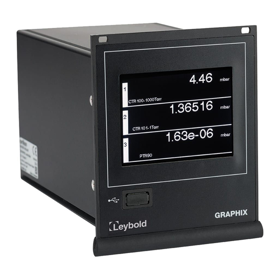
The GRAPHIX controller is a display and operating unit with a graphic user interface for sensors with an analogue or digital interface of the company Leybold GmbH or from other manufacturers. Depending on the version, the unit offers one or several channels and is... -
Page 5: Responsibility And Warranty
Based on the technical data please check first whether your measuring instrument suits your kind of application. Responsibility and Warranty Leybold GmbH will not assume any responsibility or warranty in case the operator or third persons • do not observe the information given in this document. -
Page 6: Safety
Safety General Information The GRAPHIX is supplied ready for immediate operation. These Operating Instructions shall assist you during commissioning of the instrument. For further informations please refer to the detailed Operating Instructions on the supplied USB stick. Key to Symbols Important instructions relating to technical safety and safe operation are emphasised by symbols. -
Page 7: Installation
Installation Mechanical Installation The GRAPHIX CONTROLLER can be used as follows: • Rack installation • Front panel cut-out installation • Benchtop instrument WARNING: Powering down Install the instrument or place it so that you are in a position to operate the mains power switch at any time or to ensure that the instrument can be deenergised at any time. -
Page 8: Operation
Operation Switching ON and Switching OFF • Switch the instrument on through its main switch. After switching on, the GRAPHIX controller will run the following: • Display of the start screen with the version number • Re-establishing of the most recently setup parameters •... -
Page 9: Controls
Controls The GRAPHIX controller is operated through the buttons displayed through the graphic TFT touch display. Since this is a resistive type of touchpanel, entries are possible even when using gloves. Main Menu Buttons Pressing the touchscreen for a duration of approximately 1 second displays the main menu (... -
Page 10: Symbols
Symbols 4.4.1 Symbols for the Controls Symbol Designation Explanation Next Next menu page Previous Previous menu page Scroll upward in the selection list Down Scroll downward in the selection list Return Return to the previous display Accept / confirm Configuration Start the main menu Display Mode Change display mode... -
Page 11: Symbols For The Language Selection
4.4.2 Symbols for the Language Selection Symbol Designation Explanation Language selection Start language selection menu English Select menu language EN (English) German Select menu language DE (German) Chinese Select menu language CN (Chinese) French Select menu language FR (French) Italian Select menu language IT (Italian) Japanese Select menu language JP (Japanese) -
Page 12: Measuring Mode
Measuring Mode The measuring mode is the standard mode of operation. Here the measured values of the sensors in the display modes Normal, Big or Chart are shown. Additionally status messages ( Table 6, page 12) and/or error messages ( Table 7, page 16) can be displayed. -
Page 13: Maintenance And Service
Maintenance and Service Maintenance The GRAPHIX controller does not require any special maintenance work. Configuration With the help of this parameter group they have the possibility of securing and of restoring your system parameters. In addition a suitable memory at the USB interface must be. Further resetting of the system parameters is possible on factory-installed settings. -
Page 14: Factory Setup
The GRAPHIX controller will now be ready for operation again. Update Function Should your GRAPHIX controller require a more current firmware, for example, in order to utilise new functions or sensors, please contact your next service office of Leybold GmbH or inform yourself through the Leybold homepage. 5.3.1 Preparations The firmware for the GRAPHIX controller is made available by way of a compressed *.zip... -
Page 15: Updating
5.3.2 Updating To update your GRAPHIX controller proceed as follows: • In the measurement mode, tap the touchscreen for approximately 1 second. o The main menu with an overview of the parameter groups is displayed. • To scroll, use the button o On the next page, main menu page 2/2 is displayed. -
Page 16: Troubleshooting
Troubleshooting Indication of Errors A malfunction in the GRAPHIX Controller is displayed by an error message on the screen or issued by an error number via the serial interface. Additionally, an entry is made into the error memory list, from which the 20 most recently registered errors can be displayed on the screen (... -
Page 17: System Errors
Contact your next Leybold GmbH service office. Error write eeprom none EEPROM of system not recordably. Contact your next Leybold GmbH service office. Error init eeprom none EEPROM error of system. Contact your next Leybold GmbH service office. Table 8 – System errors Error Log The GRAPHIX Controller stores the errors recognized by the system. -
Page 18: Help In Case Of Malfunctions
Figure 1, page 7). The fuse insert can be prised out with a small screwdriver. Repair Send any defective products for repair to the next Leybold service office. The Leybold GmbH will not assume any responsibility or warranty in case of repair work done by the operator or third persons on the GRAPHIX controller. -
Page 19: Storing And Waste Disposal
Storing and Waste Disposal Packaging Please retain the original packaging. You will need this packaging when storing your GRAPHIX controller or shipping it back to Leybold GmbH. Shelving The multichannel gauge must only be stored in dry room. During storage, the following ambient conditions need to be maintained: •... - Page 20 Sales and Service Germany America Great Britain Leybold Japan Co., Ltd. Tsukuba Technical Service Center 1959, Kami-yokoba Leybold UK LTD. Leybold GmbH Tsukuba-shi, Ibaraki-shi 305-0854 Unit 9 Sales, Service, Support Center (3SC) Japan Silverglade Business Park Bonner Strasse 498 Leybold USA Inc.
Need help?
Do you have a question about the GRAPHIX ONE and is the answer not in the manual?
Questions and answers