
Related Manuals for LEYBOLD COMBIVAC CM 52


Summary of Contents for LEYBOLD COMBIVAC CM 52
- Page 1 COMBIVAC CM 52 Vacuum Gauge Controller Instruction Manual GA300369449_002_C1 Catalog No. 230115 230116...
-
Page 3: Table Of Contents
Shipping Damage Safety General Information Key to the Symbols Basic Safety Information General Equipment Description COMBIVAC CM 52 THERMOVAC (Pirani) Method of Measurement Principle of Measurement for IONIVAC (Extractor or Bayard-Alpert) Connectable Gauge Heads Gauge Head Cables Accessories Technical Data General Data 4.1.1... - Page 4 Switching Functions / Relay Outputs 4.4.1 Switching Function Relay 4.4.2 Ready Signal Relay Outputs and Inputs 4.5.1 Analog Output 4.5.2 External Control 4.5.3 Serial Interfaces 4.5.3.1 RS232 4.5.3.2 RS485 4.5.4 Profibus-DP Installation Supplied Equipment Mechanical Installation 5.2.1 Rack Installation 5.2.2 Front Panel Installation 5.2.3 Benchtop Instrument...
- Page 5 Parameters Switching Function Parameters (PArA SP) 7.1.1 Basic Terms 7.1.2 Configuring the Switching Functions 7.1.3 Adjustment Range Sensor Parameters (PArA SEn) 7.2.1 Filament Material THERMOVAC (FIL) 7.2.2 Measured Value Filter (FiLt) 7.2.3 Type of Gas Correction THERMOVAC (GAS 7.2.4 Type of Gas Correction IONIVAC (GAS 7.2.5 Sensor Switch-on Type (S-on) 7.2.6...
- Page 6 Maintenance and Service Maintenance 9.1.1 General Maintenance Information Troubleshooting 9.2.1 Fault Indication 9.2.2 Error Messages 9.2.3 Help the Case of Faults 9.2.4 Fuse Replacement 9.2.5 Repair Storing and Waste Disposal 10.1 Packaging 10.2 Shelving 10.3 Waste Disposal Annex 1 - EU Declaration of Conformity Annex 2 - Declaration of Contamination GA300369449_002_C1 –...
-
Page 7: Table Of Figures
Table of Figures Figure 1 – Nameplate (Examble) Figure 2 – COMBIVAC CM 52 dimensions (in mm) Figure 3 – Rack installation Figure 4 – Front panel cutout dimensions (in mm) Figure 5 – Preparing the top side of the instrument for utilisation as a benchtop unit Figure 6 –... -
Page 8: Description
Figure 1 – Nameplate (Examble) Conforming Utilisation The COMBIVAC CM 52 is a universal vacuum gauge which by combining two principles of measurement – Pirani (Thermovac) and ionisation gauge (Ionivac) provides full coverage and control over vacuum pressures ranging between 1·10 mbar and atmospheric pressure. -
Page 9: Responsibility And Warranty
Responsibility and Warranty The Leybold GmbH will not assume any responsibility or warranty in case the operator or third persons • do not observe the information given in this document. • do not use the product as intended. • modify the product in any way (conversions, repair work etc). -
Page 10: Safety
Safety General Information The COMBIVAC CM 52 is delivered ready for operation. Even so, we recommend that you carefully read these Operating Instructions so as to ensure optimum operating conditions right from the start. This manual contains important information for understanding, installing, commissioning, operating and troubleshooting the COMBIVAC CM 52. -
Page 11: General Equipment Description
1·10 to atmospheric pressure is possible. Six switching thresholds permit the integration of the COMBIVAC CM 52 within complex vacuum control facilities. The two THERMOVAC channels are immediately active upon powering up. The IONIVAC channel may be switched on and off by one of the two THERMOVAC channels or externally or manually. -
Page 12: Connectable Gauge Heads
Connectable Gauge Heads The following gauge heads can be operated by the COMBIVAC CM 52: Gauge heads Type Catalog number THERMOVAC TR 211, DN 16 KF 157 85 TR 211, 1/8“ NPT 896 33 TR 212, DN 16 KF 158 52... -
Page 13: Technical Data
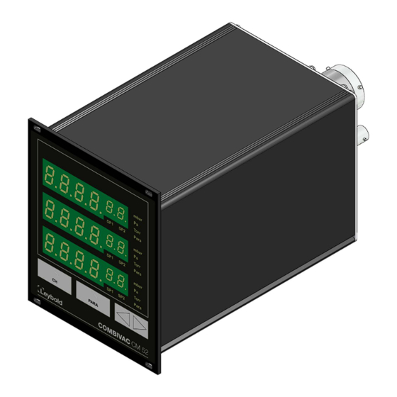
Height: 128.4 mm (3 HE) Depth: 185.0 mm ≤ 1.4 kg Wight: ≤ 280 mm approx. (including connected plugs) Installation depth: Usage: Rack installation Front panel installation Benchtop instrument Figure 2 – COMBIVAC CM 52 dimensions (in mm) GA300369449_002_C1 – 08/2017... -
Page 14: Standard Parameters (Factory Defaults)
4.1.2 Standard Parameters (factory defaults) 4.1.2.1 Sensor-dependent Parameters THERMOVAC IONIVAC Parameter Parameter description setting setting . . Switching thresold 1 – lower threshold Switching thresold 1 – upper threshold . . Switching thresold 2 –... -
Page 15: Standards
4.1.4 Standards • Conformity with respect to Low Voltage Directive 2014/35/EU • Conformity with respect to EMC Directive 2014/30/EU • Conformity with respect to RoHS Directive 2011/65/EU • Conformity with respect to WEEE Directive 2012/19/EU International/national standards as well as specifications: •... -
Page 16: Ionivac Measurement Channel
4.3.2 IONIVAC Measurement Channel Extraktor (IE514) Bayard-Alpert (IE414) – 1·10 – 1·10 Measurement range: 2·10 mbar 2·10 mbar Measurement inaccuracy: ± 2% of measured ± 2 % of measured value, value, ± 5·10 mbar ± 3·10 mbar 15 … 7 … 3 … 1 (slow … fast) Filter time constant: Anode voltage: Operation:... -
Page 17: Outputs And Inputs
Outputs and Inputs 4.5.1 Analog Output Number: 1 per measurement channel 0 – 10 VDC (limit values 0 – 10.5 VDC) Voltage range: 10.2 – 10.5 VDC Output voltage for fault: Deviation of display value: ± 0.2 % Internal resistance: 100 Ohm Characteristic: logarithmic... -
Page 18: Installation
Plastic sleeves Edge protection Adhesive feet Table 8 – Supplied equipment Mechanical Installation The COMBIVAC CM 52 can be used as follows: • Rack installation • Front panel installation • Benchtop instrument WARNING: Powering down Install the instrument or place it so that you are in a position to operate the mains power switch at any time or ensure that the instrument can be deenergised at any time. -
Page 19: Rack Installation
5.2.1 Rack Installation The COMBIVAC CM 52 has been designed for installation within a sub-rack (19", 3 HU) in accordance with DIN EN 60297 (IEC 60297) ( Figure 3, page 19). For this purpose the supplied equipment includes four neck collar screws and four plastic sleeves. -
Page 20: Benchtop Instrument
5.2.3 Benchtop Instrument When intending to use the COMBIVAC CM 52 as a benchtop instrument, then proceed as follows: • Push one of the two edge protection rubber pieces included in the delivery over the top edge of the front panel (... -
Page 21: Connections
5.3.1 Rear Side of the Instrument The Figure 7, page 21 shows the rear panel of the COMBIVAC CM 52. The way in which the individual connections have been wired is described in the following sections. Figure 7 – Rear panel of the instrument... -
Page 22: Erdung
5.3.3 Earthing The COMBIVAC CM 52 is earthed with the aid of the earth connection screw ( Figure 7, B, page 21) to the earth connection on the vacuum chamber. NOTICE: Earthing Connect the Earth connection on the vacuum chamber by means of a protective earth conductor to the earthing screw on the instrument 5.3.4... -
Page 23: Analog Output And External Control (Analog Output / Extern Control)
CAUTION: Impermissible Sensors. Gauge heads which have not been designed to be operated in connection with the COMBIVAC CM 52 or which do not comply with current EMC guidelines can impair operation of the instrument or even damage it. Always ... -
Page 24: Rs232 / Rs485 Interface (Interface Rs232 / Rs485)
Connecting: • Connect the peripheral components using a shielded connecting cable to the connection Analog Output/Extern Control on the rear of the COMBIVAC CM 52. 5.3.7 RS232 / RS485 Interface (Interface RS232 / RS485) The connection Interface RS232 / RS485 (... -
Page 25: Relay Output (Relay Output)
5.3.9 Relay Output (Relay Output) Through the connection Relay Output ( Figure 7, H, page 21 and Figure 12, page 25) you can utilise the floating relay contacts for switching purposes and ready signals. Figure 12 – Connection plug for relay output (SUB-D, 25-way) DANGER: Dangerous voltage Voltages exceeding 60 VDC or 30 VAC are dangerous when touched. -
Page 26: Operation
Operation Front Panel Figure 13, page 26 depicts the front panel of the COMBIVAC CM 52. Figure 13 – Front panel Display of channel 1 with two corresponding switching thresholds and display unit Display of channel 2 with two corresponding switching thresholds and... -
Page 27: Control Pushbuttons
6.1.2 Control Pushbuttons With the pushbutton CH you can select a measurement channel. This is necessary, for example, when wanting to switch the IONIVAC gauge head on or off, or when wanting to change the sensor parameters. The number of the selected measurement channel is displayed flashing for 10 seconds. -
Page 28: Operating Modes
Operating Modes The COMBIVAC CM 52 may be operated in one of the following operating modes: Measurement Mode The measurement mode is the standard operating mode. Here the measured values or status messages are displayed. Chapter 6.4 Measurement Mode, page 28 Parameter Mode In the parameter mode you have access to different parameters. -
Page 29: Pushbutton Functions
6.4.3 Pushbutton Functions 6.4.3.1 Measurement Channel Selection • Press the pushbutton CH. o The instrument selects the next measurement channel. The display of Para for the selected measurement channel will flash for 10 seconds. Figure 14 – Operating the pushbutton CHANNEL 6.4.3.2 Parameter Mode Selection •... -
Page 30: 6.4.3.4 Funktion Degas
6.4.3.4 Funktion Degas The IONIVAC gauge head can be cleaned by running the function Degas. For this the gauge head must be switched on ( Chapter 6.4.3.3 Switching the IONIVAC on, page 30) and the measured pressure must be below < 510 mbar. -
Page 31: Thermovac Alignment
6.4.4 THERMOVAC Alignment Ageing and contamination of the sensor filament will impair the accuracy of the pressure readout. For this it is recommended to align the THERMOVAC gauge head as required. For this, the gauge head must be orientated in the same way in which it is subsequently operated. -
Page 32: Parameter Mode
Parameter Mode 6.5.1 Selection By operating the PARA pushbutton for approximately 2 seconds the instrument changes from the measurement mode to the parameter mode. The Para indicator comes on for the channel selected in each case. When the instrument is running in the parameter mode and if no pushbutton is operated for 10 seconds, then the instrument will automatically return back to the measurement mode. -
Page 33: Operating Concept
6.5.3 Operating Concept From the measurement mode, you can select and change a certain parameter as follows: • Press the pushbutton CH, so as to select the desired measurement channel (only necessary when wanting to change a sensor parameter) o The Para status indicator flashes for the selected channel. •... -
Page 34: Parameters
Basic Terms Switching functions The COMBIVAC CM 52 contains in all 6 switching function relays, i.e. the switching functions 1 and 2 are available for each measurement channel. These switch depending on the measured pressure. The contacts of the relays are floating and may be used for switching purposes through the connection marked Relay Output (... -
Page 35: Configuring The Switching Functions
Figure 21 – Behaviour of a switching function in response to pressure changes Pressure Time Normally open contact COM Common contact Normally closed contact The range between the lower and the upper threshold value produces a certain amount of hysteresis between switching on and switching off of the relay. The hysterisis prevents rapid switching on and off of the switching function when the pressure is close to a switching threshold. -
Page 36: Sensor Parameters (Para Sen)
Sensor Parameters (PArA SEn) For each measurement channel there exists a separate set of sensor parameters. Depending on which transmitter is connected to the respective measurement channel, different parameters are available ( Table 12, page 36). Gauge heads ... -
Page 37: Type Of Gas Correction Thermovac
7.2.3 Type of Gas Correction THERMOVAC (GAS The THERMOVAC gauge heads are normally calibrated for measurements in nitrogen or air. With the aid of the parameter GAS you can set up the measurement channel to the other type of gas in each case. You may select the characteristic for a gauge head between nitrogen (N2) and argon (Ar). -
Page 38: Sensor Switch-On Type (S-On)
7.2.5 Sensor Switch-on Type (S-on) This parameter defines how the IONIVAC gauge head is switched on. You can set the switch-on time to the following values: HAnd Manual. The gauge head can be switched on by pressing the pushbutton UP (... -
Page 39: Sensor Switch-Off Type (S-Off)
7.2.8 Sensor Switch-off Type (S-oFF) This parameter defines how the IONIVAC gauge head is switched off. You can set up the switch-off type to the following values: HAnd Manual. The gauge head can be switched off by pressing the pushbutton DOWN (... -
Page 40: General Parameters (Para Gen)
General Parameters (PArA GEn) With the aid of these parameters you can generally configure the instrument. The parameters apply to all measurement channels. • Keep the pushbutton PARA depressed for approximately 2 seconds. o The instrument is now in the parameter mode. •... -
Page 41: Display Brightness (Bri)
7.3.4 Display Brightness (bri) Display brightness. Display Description High brightness Low brightness Table 17 – Values for the parameter bri 7.3.5 Profibus (Pb) Selection of the Profibus adress. Display Description – Adress 1 – 126 Table 18 – Values for the parameter Pb CAUTION: The changed Profibus bus address will only become effective after having restarted the instrument. -
Page 42: Computer Interface
Computer Interface Basics 8.1.1 Connection The COMBIVAC CM 52 can communicate with the computer through a serial interface. The interfaces RS232 or RS485 are selectively available. The selection is made through the parameter group PArA GEn in the parameter mode (... -
Page 43: Communication
Communication 8.2.1 Protocol The following log is used for communication: • 8 data bits • no parity bit • 1 stop bit The baud rate is selectable. • 9600 • 19200 • 38400 No hardware handshake is used. The messages are transferred by way of ASCII strings. A comma (0x2C) in the string is taken as a separating character. -
Page 44: Command Set (Mnemonics)
Command Set (Mnemonics) 8.3.1 Command Overview Read Commands Description Read Pressure Value. Read the pressure value for a measurement channel. Read Version Number Read the instrument software version number. Read Setpoint Status Read the status of the switching thresholds for a channel. Table 23 –... -
Page 45: Rpv (Read Pressure Value)
8.3.2 RPV (Read Pressure Value) Reading a pressure value for a measurement channel. S: RPV[a]<CR> E: b[,][TAB]x.xxxxE±xx Parameter Description Channel number 1 = Channel 1 (TM1) 2 = Channel 2 (TM2) 3 = Channel 3 (IONIVAC) Status 0 = Measured value OK 1 = Measured value <... -
Page 46: Shv (Set Hv On/Off)
Parameter Description (continued) Status SP1 0 = low 1 = high Status SP2 0 = low 1 = high 8.3.5 SHV (Set HV on/off) Setting HV on/off for IONIVAC, if switch-on and switch-off type have been set to manual. S: SHV[a, b]<CR> E: OK<CR>... -
Page 47: Sac (Save Actual Configuration)
8.3.8 SAC (Save Actual Configuration) Saving current configuration for switching threshold, sensor and general parameters. S: SAC<CR> E: OK<CR> 8.3.9 RSA (Read Serial Adress) Read adress for RS485. S: RSA<CR> E: a<CR> Parameter Description Adress 1 – 126 (01 – 7E) (output in the HEX format) 8.3.10 SSA (Set Serial Adress) -
Page 48: Sgp (Set General Parameter)
Parameter Description (continued) Brightness 0 = hoch 1 = gering Profibus 1 – 126 Baud rate 0 = 9600 1 = 19200 2 = 38400 Serial interface 0 = RS232 1 = RS485 8.3.12 SGP (Set General Parameter) Setting instrument settings. S: SGP[a, b, c, d, e, f, g]<CR>... -
Page 49: Rgc (Read Gas Correction)
8.3.13 RGC (Read Gas Correction) Reading the type of gas correction factor for a measurement channel. S: RGC[a]<CR> E: b<CR> Parameter Description Channel number 3 = Channel 3 (IONIVAC) Gas type correction factor channel Format X.XX with a range of values 0.20 – 8.00 8.3.14 SGC (Set Gas Correction) Setting the type of gas correction factor for a measurement channel. -
Page 50: Ssc (Set Sensor Control)
8.3.16 SSC (Set Sensor Control) Setting the type of sensor control for IONIVAC. S: SSC[a, b, c, x.xxxxE±xx, x.xxxxE±xx]<CR> E: OK<CR> Parameter Description Channel number 3 = Channel 3 (IONIVAC) Sensor switch-on type channel 0 = Manual 1 = External 2 = n.a. -
Page 51: Ssp (Set Set Point)
8.3.18 SSP (Set Set Point) Setting the switching thresholds for a channel. S: SSP[a, b, c, d, e]<CR> E: OK<CR> Parameter Description Channel number 1 = Channel 1 (TM1) 2 = Channel 2 (TM2) 3 = Channel 3 (IONIVAC) SP1 low (pressure value of the switching threshold in the current unit of measurement in the form of x.xxxxE±xx) SP1 high (pressure value of the switching threshold... - Page 52 Protect the instrument against moisture. Do not open the instrument. Troubleshooting 9.2.1 Fault Indication A malfunction affecting the COMBIVAC CM 52 is indicated by an error message on the display. ( Chapter 9.2.2 Error Messages, page 52) 9.2.2...
- Page 53 Send defective products for repair to your nearest Leybold GmbH service office. The compa- ny Leybold GmbH will not assume any responsibility or honour a warranty if the operator or third persons have attempted repair work on the COMBIVAC CM 52.
- Page 54 COMBIVAC CM 52 or when returning it to the company Leybold GmbH. 10.2 Shelving The COMBIVAC CM 52 must only be stored in dry room. During storage, the following ambient conditions need to be maintained: • Ambient temperature: -20 – +60 °C •...
- Page 55 Notes: GA300369449_002_C1 – 08/2017...
- Page 56 Notes: GA300369449_002_C1 – 08/2017...
- Page 57 Notes: GA300369449_002_C1 – 08/2017...
- Page 59 Return only: Person to contact: Factory-calibr. Phone : Fax: Calibration: Quality test certificate DIN 55350-18-4.2.1 End user: A. Description of the Leybold product: Failure description: Material description : Catalog number: Additional parts: Serial number: Application-Tool: Type of oil (ForeVacuum-Pumps) : Application- Process: B.
- Page 60 Sales and Service Germany America Great Britain Leybold Japan Co., Ltd. Tsukuba Technical Service Center 1959, Kami-yokoba Leybold UK LTD. Leybold GmbH Tsukuba-shi, Ibaraki-shi 305-0854 Unit 9 Sales, Service, Support Center (3SC) Japan Silverglade Business Park Bonner Strasse 498 Leybold USA Inc.
Need help?
Do you have a question about the COMBIVAC CM 52 and is the answer not in the manual?
Questions and answers