Midea CHEST FREEZER Series Service Manual
Hide thumbs
Also See for CHEST FREEZER Series:
- Service manual (41 pages) ,
- Service manual (34 pages) ,
- Service manual (37 pages)
Table of Contents
Advertisement
Service Manual_2018-V2.0
Service Manual
CHEST FREEZER SERIES
Applicable Models
Model Code
Applicable Models
HS-252CN
CE-BD194-FQ
22032010000134,
The picture in this service manual is only for reference, and specific appearance and configuration
are subject to the real product.
This manual mainly teaches the method, the specific work skill needs engineer to accumulate
through the daily work.
1
Advertisement
Table of Contents

Related Manuals for Midea CHEST FREEZER Series


Summary of Contents for Midea CHEST FREEZER Series
- Page 1 Service Manual_2018-V2.0 Service Manual CHEST FREEZER SERIES Applicable Models Model Code Applicable Models HS-252CN CE-BD194-FQ 22032010000134, The picture in this service manual is only for reference, and specific appearance and configuration are subject to the real product. This manual mainly teaches the method, the specific work skill needs engineer to accumulate...
- Page 2 Manufacturers or distributors are not responsible for the content of the Manual and interpretation thereof. Midea Refrigerators Technical Maintenance Manual Copyright @2017 All rights reserved. Replication of all or part of the Manual in any forms shall not be allowed without written approval by the Overseas Sales Corporation of Midea Refrigerators.
-
Page 3: Table Of Contents
Service Manual_2018-V2.0 Contents SIGNIFICANT UPDATE NOTES(NONE) ......................5 2. SAFETY WARNING CODE ............................6 2.1 W ........................... 6 ARNING FOR OPERATION SAFETY 2.2 S AFETY INSTRUCTION FOR REFRIGERANT ......................... 8 3. TRANSPORT ................................9 3.1 C ONTAINER TRANSPORT ............................9 3.2 H ANDLING ................................. - Page 4 Service Manual_2018-V2.0 10. COMPRESSOR ..............................30 10.1C OMPRESSOR ON AND OFF ONTROL SPECIFICATIONS ..................30 10.2V )................30 ARIABLE FREQUENCY DRIVER BOARD FAULT ANALYSIS 11. TROUBLESHOOTING METHOD ........................31 11.1N ................................31 OT COOLING 11.2 N O WORKING OF COMPRESSOR ..........................
-
Page 5: Significant Update Notes(None)
Service Manual_2018-V2.0 1. Significant update notes(None) -
Page 6: Safety Warning Code
Service Manual_2018-V2.0 2. Safety Warning Code 2.1 Warning for operation safety Important Safety Instructions CAUTION RISK OF ELECTRIC SHOCK DO NOT OPEN This symbol indicates that dangerous voltage constituting a risk of electric shock is present within your freezer. This symbol indicates that there are important operating and maintenance instructions in the literature accompanying your freezer. - Page 7 Service Manual_2018-V2.0 CONNECTING ELECTRICITY Electrical Shock Hazard. Failure to follow these instructions can result in death, fire, or electrical shock. Plug into a grounded 3-prong outlet. Do not remove the ground prong. Do not use an adapter. WARNING Electric Shock Hazard Failure to follow these instructions can result in electric shock, fire, or death.
-
Page 8: Safety Instruction For Refrigerant
Service Manual_2018-V2.0 responsibility to comply with federal and local regulations when disposing of this product. 12) This freezer is intended to be used in household and similar environments. 13) Do not store or use gasoline or any flammable liquids inside or in the vicinity of this freezer. -
Page 9: Transport
Service Manual_2018-V2.0 3. Transport 3.1 Container transport Packing Size(LWH): 985x545x885 Container 40HQ(12.032*2.352*2.690)m specification(LWH) What floor Door direction Cabinet direction floor Outside Container s cheme,and floor Outside floor Outside Container QTY floor Outside Total Container diagram Notes:The goods on the top layer of the container may conflict with the position of the side corner of the container . -
Page 10: Handling
Service Manual_2018-V2.0 3.2 Handling Handling 1)Protect the refrigerator in moving it,Same as shown as lef t photo, please move it by handcart with cushion 2)Remove all packing materials and bottom cushion, the m ove into house for placement 3)After moving it to appropriate location, wait for 2 hours bef ore power on. -
Page 11: Installation And Commissioning
Service Manual_2018-V2.0 4. Installation and commissioning 4.1Door Disassembly and Assembly(None) The refrigerator door needs to be dismantled if it cannot enter the room in the whole. 4.2 Installation location Installation location Location that is easy for ventilation shall be chosen to facilitate heat dissipation, enhance its performance and reduce the energy consumption. -
Page 12: Installation Of Door Lock
Service Manual_2018-V2.0 1- Handle 2- M5*14 screw(two) 3- Screw hole cover (two) 1) The handle is inserted below the display control board of door, aligning with the screw hole. 2) Fixing the handle by using the screw. 3) Assemble the screw hole cover onto the screw hole. 1.Fix the lock loop to its mounting hole near the frame in the front side plate of the box with a M4x20 or M4x8 screw. -
Page 13: Product Configuration And Dimension
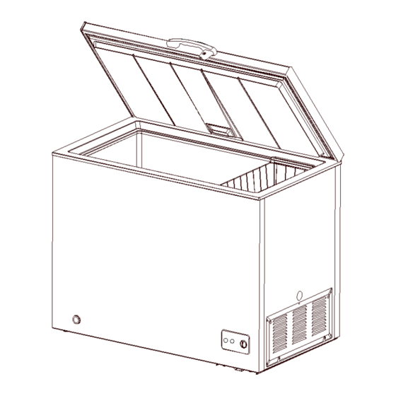
Service Manual_2018-V2.0 5. Product configuration and dimension 5.1 Main parts and their names (The picture is only for reference, and specific appearance and configuration are subject to the real product) Freezer chamber Refrigerator chamber ❶ Door shell ❼ Levelling feet ❷... -
Page 14: External Dimension
Service Manual_2018-V2.0 5.2 External dimension HS-252CN Code Size (mm) Description Height to Top of Case Width Depth/Hinge Depth 1335 Height (Door open) (The picture is only for reference) -
Page 15: Location Of S/N
Service Manual_2018-V2.0 5.3 Location of S/N Some products also have S/N on the lower part of the right side of the Cabinet. -
Page 16: Product Specification
Service Manual_2018-V2.0 6. Product specification 6.1 Electrical parameters Applicable Models HS-252CN Product Name CE-BD194-FQ Product Code 22032010000134 Item Specification Specification Refrigerant R600a Compressor PZ70E1H 8EA19C3/QP2-15/QP2- Starter(PTC) 15/QP2-15 Overload protector(OLP) 3TM117SF2/DRB12S61A1 Integrate PTC+OLP None Variable frequency driver board None Capacitor 3.0μF Rmc:40.1±7%Ω... -
Page 17: Circuit Diagram
Service Manual_2018-V2.0 6.3 Circuit diagram... -
Page 18: Refrigerating Piping System And Circulating Route Of Cooling Air
Service Manual_2018-V2.0 7.Refrigerating piping system and circulating route of cooling air 7.1 Refrigerating piping system ❶Compressor→❷ Back hanging wire tube condensor →❸ Front condenser →❹Dry filter→❺Capillary tube→❻Evaporator 7.2 Special soldering position... -
Page 19: Dismantling Of Parts
Service Manual_2018-V2.0 8. Dismantling of parts 8.1 Parts on the door Door seal 1)Pull the door seal from the corner 2)Take efforts until door seal totally detaches from door inner liner groove, remove the door seal 3)Fixing the four corners and pressing smoothly. The hinge cover The hinge cover teardown 1) Strongly apart a proper angle with your hands along... -
Page 20: Parts Inside The Refrigerator
Service Manual_2018-V2.0 The hinge cover install 1) Apart a proper angle with your hands along the side wall of the lower hinge cover when the refrigerator door is closed, align to the side wall of hinge and push forward until the hinge cover boss is fully and correctly inserted into the hinge holes;... -
Page 21: Light System
Service Manual_2018-V2.0 8.3 Light system Door lamp Door lamp disassembly 1) Open the refrigerator door to dismantle the lamp cover; Note: There are two kinds of door lamps, namely, incandescent lamp and LED lamp, and what is shown in the picture is the incandescent lamp. 2) Screw off the screws to remove the incandescent lamp holder or LED lamp panel;... - Page 22 Service Manual_2018-V2.0 1)Cut off the compressor pipeline.-❶Cut off the process pipeline.-❷Cut off the low-pressure muffler.- ❸Cut off the high-pressure exhaust pipe. 2-1)Remove the screws(for some models) -Two screws outside -One screw inside 2-2)Remove the metal clamp(for some models) -Disassembly the metal clamp that is fix the electric appliance shield 3)Remove the clipping strip Slowly pull it out...
- Page 23 Service Manual_2018-V2.0 5)Remove the starter and protector Unplug the starter and protector (you can use a screwdriver to pry it slowly) 6)Loosen the screw of the compressor bottom plate, remove the floor together with the compressor from the box. 7)Use the wrench to remove the bolts by steps❹❺❻❼, replace the compressor and reverse process can complete installation.
- Page 24 Service Manual_2018-V2.0 9)Replace the compressorand welding the compressor pipeline.-❿Welding the process pipeline.-⓫Welding the low-pressure muffler.-⓬Welding the high-pressure exhaust pipe. 10)Replace the filter, Cu-Fe tubes welding ⓭ used Ag welding rod, Cu-Cu tubes welding ⓮ used Cu welding rod. 11)Vacuum system,The degree of vacuum below 6Pa. 12)Perfusion refrigerant.
-
Page 25: Temperature-Control Box Assembly
Service Manual_2018-V2.0 ❷ -1 Front condenser pipeline-1 ⓫ Suction Pipe ❸ -2 Hanging wire condenser pipeline-2 ⓬ -1 Hanging wire condenser pipeline-1 ❹ -1Anti-dew pipe-1 ⓭ -2 Front condenser pipeline-2 ❺ Temperature-control box assembly ⓮ -2Anti-dew pipe-2 ❻ Drying filter ⓯... - Page 26 Service Manual_2018-V2.0 Destuffing 1)Take out of temperature control box assembly by pressing shrapnel with the hands. Note:there are four shrapnels separately in the four corners,require enough strength to press shrapnel. Suggest pressing one and pushing toward the corner, as the above one by one. 2)Take out of temperature control box assembly after four corner pushed out.
- Page 27 Service Manual_2018-V2.0 4)Pull out the wiring harness and indicator light 5)Pull out the control knob 6)Pull out the fixed nut of the thermostat 7) remove the indicator light and thermostat, the reverse operation is for assembly...
-
Page 28: Function And Operation
Service Manual_2018-V2.0 9. Function and operation 9.1 Operation panel Icons Button ❶ Power indicator Ⓐ refrigeration gear ❷ Run indicator Ⓑ freezer gear indicator Ⓒ Quick freeze gear ❸ Fast freeze ❶ Power indicator Ⓐ “1-2-3-4-5-6”freezer gear ❷ Run indicator Ⓑ... -
Page 29: High Temperature An Alarm
Service Manual_2018-V2.0 9.2Temperature control 1) Connect the freezer to power supply and “Power” indicator will shine; “Run ”indicator will shine in operation; “Fast freeze” indicator will shine in quick freezing 2) The temperature of the chamber is adjusted through the thermostat knob. The number “1, 2, 3, 4, 5, 6,7,8”do not mean a specific temperatures, the lower the number is, the higher the temperature inside will be and verse versa. -
Page 30: Compressor
Service Manual_2018-V2.0 10. Compressor 10.1Compressor on and off Control specifications 1.1 When one of the following conditions is met, the compressor stops: 1) Tr ≤ Trt; 2) The compressor runs continuously for more than 3 hours (Stop 5 minutes); 1.2 When all the following conditions are met, the compressor starts up: 1) Tr ≥Trk;... -
Page 31: Troubleshooting Method
Service Manual_2018-V2.0 11. Troubleshooting Method 11.1Not cooling... -
Page 32: No Working Of Compressor
Service Manual_2018-V2.0 11.2 No working of compressor 11.3Thermostat malfunction-Undercooling... -
Page 33: Light Is Not On
Service Manual_2018-V2.0 11.4 Light is not on 11.5 Noise... -
Page 34: Figures And Details Of Repair Parts
Service Manual_2018-V2.0 13. Figures and details of repair parts See this section in the TSP. - Page 35 MIDEA appliances after sales website For more information about Midea appliances after sales, please visit the tsp.midea.com tsp.midea.com For more information about the service manual, please visit the tsp.midea.com...
Need help?
Do you have a question about the CHEST FREEZER Series and is the answer not in the manual?
Questions and answers
Operator manual for CHEST FREEZER HD 670CE(N)/351515