Midea CHEST FREEZER Series Service Manual
Hide thumbs
Also See for CHEST FREEZER Series:
- Service manual (35 pages) ,
- Service manual (34 pages) ,
- Service manual (37 pages)
Table of Contents
Advertisement
Quick Links
Service Manual
(The picture in this service manual is only for reference, and specific appearance and configuration are
subject to the real product)
CHEST FREEZER SERIES
1
Service Manual_2018-V1.0
Applicable Models
CE-BD138- FT
CE-BD194- FT
Prepared by
R&D:Zhouwd2
QA:WuXinbin
Reviewed by
SVC:Zhang Kun
R&D:ZhangHuawei
Approved by
SVC:GuangTaoshuai
Model Code
22032010002321
22032010003141
Advertisement
Table of Contents

Related Manuals for Midea CHEST FREEZER Series


Summary of Contents for Midea CHEST FREEZER Series
- Page 1 Service Manual_2018-V1.0 Service Manual CHEST FREEZER SERIES Applicable Models Model Code CE-BD138- FT 22032010002321 CE-BD194- FT 22032010003141 Prepared by R&D:Zhouwd2 QA:WuXinbin Reviewed by SVC:Zhang Kun R&D:ZhangHuawei Approved by SVC:GuangTaoshuai (The picture in this service manual is only for reference, and specific appearance and configuration are...
- Page 2 Manufacturers or distributors are not responsible for the content of the Manual and interpretation thereof. Midea Refrigerators Technical Maintenance Manual Copyright @2017 All rights reserved. Replication of all or part of the Manual in any forms shall not be allowed without written approval by the Overseas Sales Corporation of Midea Refrigerators.
-
Page 3: Table Of Contents
Service Manual_2018-V1.0 Contents 1. Safety Warning Code ............................5 1.1 Warning for operation safety ........................5 1.2 Safety instruction for refrigerant ....................... 7 2. Description for product features ......................... 8 3. Installation and commissioning .......................... 9 3.1 Handling ............................... 9 3.2 Door Disassembly and Assembly ...................... - Page 4 Service Manual_2018-V1.0 10. Circuit description ............................. 31 10.1 Power Supply(None) ..........................31 10.2 Test circuit for door switch(None) ......................31 10.3 Temperature test circuit(None) ......................31 10.4 Freezer chamber fan motor circuit (None) ..................31 10.5 refrigerating chamber fan motor circuit (None) .................. 31 10.6 Condensation fan circuit (None) ......................
-
Page 5: Safety Warning Code
Service Manual_2018-V1.0 1. Safety Warning Code 1.1 Warning for operation safety Important Safety Instructions CAUTION RISK OF ELECTRIC SHOCK DO NOT OPEN This symbol indicates that dangerous voltage constituting a risk of electric shock is present within your freezer. This symbol indicates that there are important operating and maintenance instructions in the literature accompanying your freezer. - Page 6 Service Manual_2018-V1.0 CONNECTING ELECTRICITY Electrical Shock Hazard. Failure to follow these instructions can Plug into a grounded 3-prong outlet. result in death, fire, or electrical shock. Do not remove the ground prong. Do not use an adapter. WARNING Electric Shock Hazard Failure to follow these instructions can result in electric shock, fire, or death.
-
Page 7: Safety Instruction For Refrigerant
Service Manual_2018-V1.0 13) Do not store or use gasoline or any flammable liquids inside or in the vicinity of this freezer. 14) Do not use extension cords or ungrounded (two-prong) adapters with this freezer. If the power cord is too short, have a qualified electrician install an outlet near the freezer. Use of an extension cord can negatively affect the freezer’s performance. -
Page 8: Description For Product Features
Service Manual_2018-V1.0 2. Description for product features This product is provided with following features: 1) Square shaped temperature control panel, two or three indicator light... -
Page 9: Installation And Commissioning
Service Manual_2018-V1.0 3. Installation and commissioning 3.1 Handling Handling 1)Protect the refrigerator in moving it,Same as shown as left photo, please move it by handcart with cushion 2)Remove all packing materials and bottom cushion, the n move into house for placement 3)After moving it to appropriate location, wait for 2 hours before power on. -
Page 10: Leveling Of The Refrigerator
Service Manual_2018-V1.0 3.4 Leveling of the refrigerator Leveling of the refrigerator If the refrigerator cannot be placed steadily, adjust the footing to level it. 3.5 Door reversal Door reversal Door reversal None 3.6 Installation of handle Installation of handle 1- Handle 2- M5*14 screw(two) 3- Screw hole cover (two) 1) The handle is inserted below the display control board... -
Page 11: Installation Of Door Lock
Service Manual_2018-V1.0 3.7 Installation of door lock Installation of door lock Installation of door lock With the door handle together 3.8 Adjustment to level the door Adjustment to level the door Adjustment to level the door None 3.9 Adjustment to shelves Adjustment to shelves Adjustment to shelves None... -
Page 12: Terms
Service Manual_2018-V1.0 4. Terms 4.1 Definition of model (None) 4.2 Location of nameplate(None) -
Page 13: Product Specification
Service Manual_2018-V1.0 5. Product specification 5.1 Type specification(None) 5.2 Electrical parameters Product Name CE-BD138-FT None None CE-BD194-FT Product Code 22032010002321 22032010003141 None None Item Specification Specification Specification Specification Compressor SZ80E1H-SCL SZ90E1H-SCL None None Starter(PTC) 8EA19C1 8EA19C1 None None Overload 3TM181TF2 3TM181TF2 None None... -
Page 14: Inside Temperature
Service Manual_2018-V1.0 5.3 Inside temperature Temperature tolerance ≤ 2 The highest ( Lowest ( Compartment Freezing Refrigerating None None Variable temperature None None 5.4 Defrosting parts Item Initial defrosting period Normal defrosting period Defrosting period None None Defrosting sensor None None Defrosting temperature None... -
Page 15: Circuit Diagram
Service Manual_2018-V1.0 5.5 Circuit diagram... -
Page 16: Internal View And Dimension
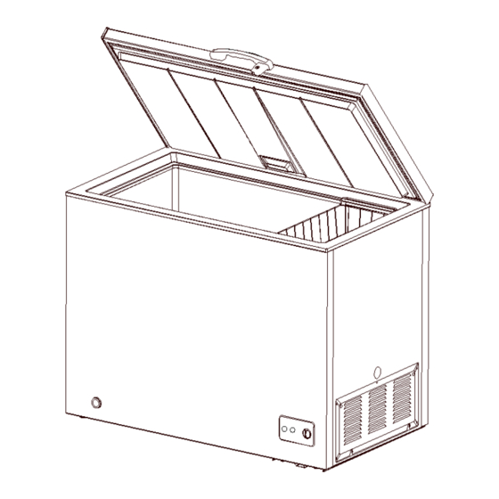
Service Manual_2018-V1.0 6. Internal view and dimension 6.1 Main parts and their names Freezer chamber Freezer chamber ❶ Door shell ❼ Levelling feet ❷ The door end cover ❽ Compressor mounting panel ❸ Door gasket ❾ Temperature-control panel ❹ Door liner ❿... -
Page 17: External Dimension
Service Manual_2018-V1.0 6.2 External dimension Size (mm) Size (mm) Size (mm) Code Description BD99 BD142 BD198 Height to Top of Case Width Depth/Hinge Depth 1320 1320 Height (Door open) 1320... -
Page 18: Refrigerating Piping System And Circulating Route Of Cooling Air
Service Manual_2018-V1.0 7. Refrigerating piping system and circulating route of cooling air 7.1 Refrigerating piping system ❶Compressor→❷Right condenser→❸Left Condenser→❹Dry filter→❺Capillary tube→❻Evaporator 7.2 Circulating route of cooling air... -
Page 19: Dismantling Of Parts
Service Manual_2018-V1.0 8. Dismantling of parts 8.1 Parts on the door Door seal 1)Pull the door seal from the corner 2)Take efforts until door seal totally detaches from door inner liner groove, remove the door seal 3)Fixing the four corners and pressing smoothly. The hinge cover 1)Push the hinge cover from the bottom to the top and appear displacement for the hinge cover. -
Page 20: Parts Inside The Refrigerator
Service Manual_2018-V1.0 2)Pull down hinge cover from the bottom. 3)Slap forcefully the top hinge cover with the palm, and wear safety gloves for fear of cutting the hand. After the displacement, pull down the hinge cover. Door light disassembly and assembly None Door light disassembly and assembly 8.2 Parts inside the refrigerator... -
Page 21: Light System
Service Manual_2018-V1.0 Counterclockwise to remove the pipe cover Ice tray Ice tray None 8.3 Light system Light Light None Light switch Light switch None Indicator lamp Indicator lamp POWER 8.4 Evaporator and temperature sensing system Freezer sensor Freezer sensor None Ambient temperature sensor Ambient temperature sensor None... - Page 22 Service Manual_2018-V1.0 Pull down the screw, open the shutter. Compressor and the cooling system pipe 1)Cut off the compressor pipeline.-❶Cut off the process pipeline.-❷Cut off the low-pressure muffler.-❸Cut off the high-pressure exhaust pipe. 2-1)Remove the screws(for some models) -Two screws outside -One screw inside 2-2)Remove the metal clamp(for some models) -Disassembly the metal clamp that is fix the electric...
- Page 23 Service Manual_2018-V1.0 4-1)Remove the screws(for some models) -Two screws outside -One screw inside 4-2)Remove the metal clamp(for some models) -Disassembly the metal clamp that is fix the electric appliance shield 5)Remove the starter and protector Unplug the starter and protector (you can use a screwdriver to pry it slowly) 6)Loosen the screw of the compressor bottom plate, remove the floor together with the compressor from the...
- Page 24 Service Manual_2018-V1.0 7)Use the wrench to remove the bolts by steps❹❺❻❼, replace the compressor and reverse process can complete installation. 8)Use Pipe cutter cut off the condenser tube❽, then Shear off capillary ❾ by the capillary tube scissors. 9)Replace the compressorand welding the compressor pipeline.-❿Welding the process pipeline.-⓫Welding the low-pressure muffler.-⓬Welding the high-pressure exhaust pipe.
- Page 25 Service Manual_2018-V1.0 11)Vacuum system,The degree of vacuum below 6Pa. 12)Perfusion refrigerant. 13)Use the vise grip pliers clamp the middle of the process pipe, then seal welding process tube⓯⓰. Piping system in the compressor case ❶ Capacitor ❿ Compressor ❷ -1 Front condenser pipeline-1 ⓫...
-
Page 26: Temperature-Control Box Assembly View
Service Manual_2018-V1.0 Condenser fan motor Fan motor None Standby condenser None 8.7 Temperature-control box assembly view Temperature-control box assembly view ❶ screw ❹ Temperature-control panel ❷ Temperature-control box ❺ TEMP. control knob ❸ Thermostat ❻ Indicator light... - Page 27 Service Manual_2018-V1.0 Destuffing 1) Pull down the screw, open the shutter. 2)Take out of temperature control box assembly by pressing shrapnel with the hands. Note:there are four shrapnels separately in the four corners,require enough strength to press shrapnel. Suggest pressing one and pushing toward the corner, as the above one by one.
- Page 28 Service Manual_2018-V1.0 4) Remove the control box screw, take out the control box cover 5)Pull out the wiring harness and indicator light 6)Pull out the control knob 7)Pull out the fixed nut of the thermostat 8) remove the indicator light and thermostat, the reverse operation is for assembly...
-
Page 29: Function And Operation
Service Manual_2018-V1.0 9. Function and operation 9.1 Operation panel Icons Button ❶ Power indicator Ⓐ “MIN-MAX”freezer gear Ⓑ “OFF” 9.2 Temperature control 1)Connect the freezer to power supply and “Power” indicator (the green light ) will shine. 2) The interior temperature of the freezer is adjusted through the thermostat knob,Clockwisely rotate thethermostat knob and the interior temperature will drop. - Page 30 Service Manual_2018-V1.0 used to the accelerate de-icing process. Please remove the food and put in a cool place when defrosting before removing accessories.
-
Page 31: Circuit Description
Service Manual_2018-V1.0 10. Circuit description 10.1 Power Supply(None) 10.2 Test circuit for door switch(None) 10.3 Temperature test circuit(None) 10.4 Freezer chamber fan motor circuit (None) 10.5 refrigerating chamber fan motor circuit (None) 10.6 Condensation fan circuit (None) 10.7 Fan motor circuit of the ventilation door(None) 10.8 Resistance value of the sensor (R/T) (None) -
Page 32: Troubleshooting Method
Service Manual_2018-V1.0 11. Troubleshooting Method 11.1 Not cooling... -
Page 33: Not Working Of Compressor
Service Manual_2018-V1.0 11.2 Not working of compressor 11.3 Thermostat malfunction-Undercooling... -
Page 34: Light Is Not On
Service Manual_2018-V1.0 11.4 Light is not on 11.5 Noise... -
Page 35: Figures And Details Of Repair Parts(Documents Are Provided Separately)
Service Manual_2018-V1.0 12. Figures and details of repair parts(Documents are provided separately) 12.1 Figures 12.2 List of parts and components CE-BD138-FT 22032010002321 序号 零部件名称 数量 物料编码 Chinese Name Part Name Quantity BOM Code Freezer door assembly 12832000007562 冷冻室门体总成 Door gasket 12132000000392 门封条... - Page 36 Service Manual_2018-V1.0 Basket 吊篮 Cabinet assembly 12832000008267 箱体总成 十字槽凹穴六角头法兰面自攻 tapping screw 10.0 11303116000031 螺钉 No wheel corner plate 12232000000698 无轮角板 Water pipe cover 12132000000361 水管盖 tapping screw 11303119000199 十字槽扁圆头自攻螺钉 Temperature-control box 12132000000017 温控盒 Ordinary type temperature 17431000001327 普通型温控器 controller Temperature-control panel 12132000000057 温控面板...
-
Page 37: Appendix
Service Manual_2018-V1.0 Water pipe cover 12132000000361 水管盖 tapping screw 10.0 11303119000199 十字槽扁圆头自攻螺钉 Temperature-control box 12132000000017 温控盒 Ordinary type temperature 17431000001327 普通型温控器 controller Temperature-control panel 12132000000057 温控面板 Indicator hole cover 17431000000318 指示灯 Button 12131000003600 旋钮 Power cord 17431000001097 电源线 Wires 线束 Compressor mounting 12232000000709 压缩机安装板... - Page 38 Service Manual_2018-V1.0 slotted screw and rivet assemble and screwdriver/scraper disassemble hinge and compressor screw Socket spanner 5/16″ assemble and disassemble display panel and air duct cover Sucker disassemble Allen wrench handle assemble and (2.8~4mm) disassemble Vise grip pliers sealing process tube Nipper Assistive tooling pliers/diagonal pliers...
- Page 39 Service Manual_2018-V1.0 Pipe cutter, Flaring Pipe cutting,flaring device Electronic digital Test temperature thermometer Measurement with resistance, Multi meter voltage, current and so on. Equipment Name Main Usage Photo Vacuum pump with vacuum pumping gauge Electronic scale weighing refrigerant/gas High pressure pipe and cooling nitrogen with system(condenser, evaporator,...
- Page 40 Service Manual_2018-V1.0 welding point leakage detect, if hand leak detector no, use soap-suds Material Name Main Usage Photo Charge the refrigerant Process pipeline system failure to be Involving a Dry filter replaced Copper welding rod Copper-Copper tubes welding Not Copper-Copper tubes Silver solder(>...
- Page 41 MIDEA appliances after sales website tsp.midea.com For more information about Midea appliances after sales, please visit the For more information about the service manual, please visit the tsp.midea.com tsp.midea.com For more information about the EV and SBOM, please visit the...
Need help?
Do you have a question about the CHEST FREEZER Series and is the answer not in the manual?
Questions and answers