Table of Contents
Advertisement
Advertisement
Table of Contents

Related Manuals for SEW-Eurodrive MOVITRAC 0500


Summary of Contents for SEW-Eurodrive MOVITRAC 0500
- Page 1 ® MOVITRAC 0500 Frequency Inverters Operating Instructions Edition 01/97...
-
Page 2: Inverter Design
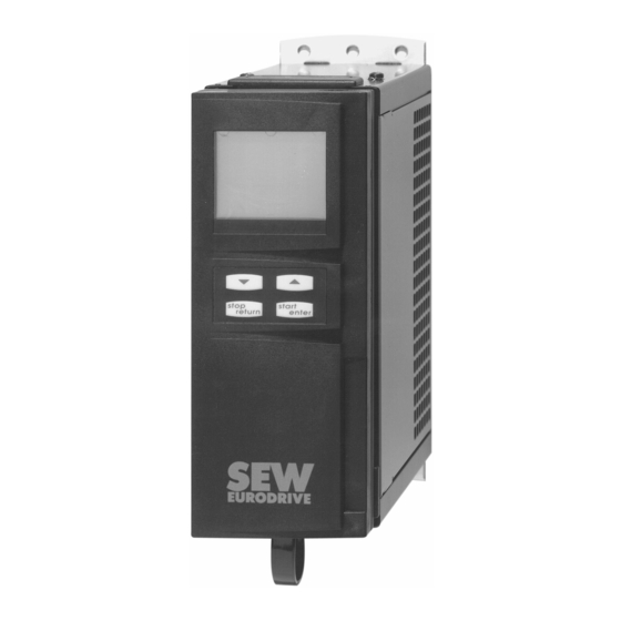
Inverter Design ® Fig. 1: MOVITRAC 0500 with FBG 01 keypad and FKS 01 heat sink 00401BXX ® MOVITRAC 0500 frequency inverter - basic unit with cover closed ® MOVITRAC 0500 frequency inverter - basic unit with cover removed LED H1 (red) operating display / fault signal LED H2 (green) operating display Poti P1, internal setpoint potentiometer Socket X3 for FBG 01 keypad... -
Page 3: Table Of Contents
Table of Contents Page Inverter design ........2 General Notes . -
Page 4: General Notes
General Notes Check the inverter for packaging damage as soon as you receive it. Inform the carrier of any packaging damage immediately. A requirement of fault-free operation and fulfilment of any rights to claim under guarantee is that these instructions and remarks are followed. Therefore read these instructions carefully before you start working with the unit. - Page 5 General Notes Name plate Example: 00423AXX CE Mark: ® MOVITRAC 0500 frequency inverters conform with Low Voltage Directive 73/23/EEC and if installed in compliance with EMC regulations (→ Sec. 3.2) with EMC Directive 89/336/EEC. Type designation Example: ® MOVITRAC 0504 - 231 - 1 - 00 Version: = standard Quadrants:...
-
Page 6: Safety Notes
Safety notes Installation, commissioning and servicing of the inverter may only be performed by qualified electrical personal with the relevant training in accident prevention, in compliance with the valid regulations (e.g. EN 60204, VBG 4, DIN VDE 0100/0113/0160). When installing and commissioning the motor and brake, the relevant instructions must be observed! Before removing the front cover, the inverter must be disconnected from the supply. -
Page 7: Electrical Installation
Electrical Installation The safety instructions (→Sec. 2, P. 6) must be strictly observed during the electrical installation! Installation instructions Run power cables and electronic leads in separate cable ducts. (Data →Sec. 6). Power cable: based on the input current I at rated load mains (Data →Sec. -
Page 8: Emc-Compliant Installation
Electrical Installation EMC-compliant installation ® When installed in accordance with the instructions for EMC-compliant installation MOVITRAC 0500 inverters meet the requirements for compliance with EMC Directive 89/336/EEC. Interference immunity: ® MOVITRAC 0500 frequency inverters comply with all the immunity requirements of EN 50082-2. In combination with shielded leads even more stringent levels than those stipulated in the standard are met. -
Page 9: Wiring Diagram For The Basic Unit
Wiring diagram for the basic unit F 11 K 11 Input filter NF...-... Connection of keypad FBG 01 ® MOVITRAC 0500 PE * -UZK +UZK 1 2 3 4 5 6 7 8 9 10 11 Brake chopper BRC 03 with... -
Page 10: Brake Rectifier Connection
24 V 24 V X1:11 X1:11 X1:8 X1:8 ® ® MOVITRAC 0500 MOVITRAC 0500 3 phase 3 phase Brake Brake a) Switch-off in the AC circuit b) Switch-off in the AC and DC circuits for very short brake reaction times Fig. -
Page 11: Commissioning
Commissioning The safety instructions ( → Sec. 2, P. 6) must be strictly observed during commissioning! Condensed commissioning instructions for standard applications (FBG 01 keypad not required) 1. Check installation (connection to the supply 1 x 200...240 V , motor voltage 3 x 200...240 V 2. -
Page 12: Operation With Fbg 01 Keypad
Commissioning Operation with FBG 01 keypad 4.2.1 Connection and operating displays of the FBG 01 keypad ® The MOVITRAC 0500 basic unit comes without keypad. The optional FBG 01 keypad can be used to display and adjust the inverter parameters. Disconnect the inverter from the supply and wait for 2 minutes! Turn the interlock to open the inverter cover and... -
Page 13: Menu Structure
Commissioning 4.2.2 Menu structure FBG 01 operation: Arrow keys Are used to select menu branches/parameters and to edit parameters. → moves to next menu branch or parameter or Press once effects smallest possible change in value. → scrolls automatically. Keep pressed Press both keys briefly →... - Page 14 Commissioning The four menu branches: V A L PARA CTRL CARD MENU MENU MENU MENU start start stop start stop start stop stop enter return enter return enter return enter return CTRL VA L PARA WRITE VA L CARD FMIN1 50.0 READ WRITE...
-
Page 15: Manual Operation / Motorized Potentiometer
Commissioning 4.2.3 Manual operation / motorized potentiometer CTRL Call up CTRL menu branch. MENU stop start enter return Enter password (factory setting 573) and confirm. CTRL start stop enter return The frequency input for the inverter is 0Hz. CTRL Set the required frequency input using the arrow CTRL CTRL 30.0... -
Page 16: Setting The Signal Mode For Fsina And Souta
Commissioning Setting the signal mode for FSINA and SOUTA The signal mode is set with the jumper on jumper strip X2: Inhibit inverter, STR and STL = “0". Factory setting Disconnect the inverter from the supply. Unscrew and remove terminal strip X1. Use suitable tool, e.g. -
Page 17: Complete Parameter List
Commissioning Complete parameter list 4.4.1 Menu branch VAL, display parameters Level Code Function Range Actual Value CNTL (Not for use)X8 SOUT Standard output signal 0...20000 (10 G = 12 F x 86 KG) STAT (Not for use) Output frequency 0.00...999.00 Hz Output voltage 0...230 V Apparent current... -
Page 18: Menu Branch Para, Adjustable Parameters
Commissioning 4.4.2 PARA menu branch, adjustable parameters Data Setting Level No. Code Function Value range after (Factory setting commis- underlined) sioning MODE Operating mode 0/1/2/3/4 CSEL (Not for use) Do not change! Frequency setpoint FSSEL 0, 4...15 selector FSSIO (Not for use) Do not change! BARG... - Page 19 Commissioning Level Data No Code Function Value range Setting (Factory setting after underlined) commis- sioning 48 IxR I x R compensation 0...1 49 SC Slip compensation 0...1 50 IN Motor rated current MC 0504: 0.00...2.85 A MC 0504: 0.00...4.80 A 51 COS Power factor x 100 0.00...100.00...
-
Page 20: Operation And Service
Operation and Service Operating displays The LED operating displays indicate the following: H1 (red) H2 (green) Indication Mains supply OFF Mains supply ON, inverter is ready for operation Inverter started Inverter started and overload protection active Fault indication by inverter (for fault information details → Sec. 5.3) BLINKING Operating conditions / Overload condition Operating conditions:... -
Page 21: Fault Information
Operation and Service Fault information In the event of a fault the LED H1 will keep flashing (red). LED H1 (red) flashing Cause Remedy / Comments once Processor fault Reset, power down and power up again twice Power down, flashing up to Automatic reset <... -
Page 22: Sew Electronics Service
Operation and Service The FBG 01 keypad indicates the faults the same as the basic unit, and in addition signals the following faults: Code Meaning In fault memory VAL 95 ERR1 Operating errors ATT1 Parameter adjustment not allowed while motor is running ATT2 Manual operation via FBG 01 keypad not allowed if motor is already running ATT3... -
Page 23: Technical Data
Technical Data Basic units ® MOVITRAC type 0504-231-1 0508-231-1 Inverter part number 1Q 825 877 5 825 878 3 Rated output power 0.75 kVA 1.27 kVA (at V = 1 x 230 V mains Continuous output power (110% P 0.84 kVA 1.4 kVA cont (at V... - Page 24 Technical Data ® MOVITRAC series 0500 General electronic data Speed setpoints X1:1 Reference voltage for setpoint potentiometer: +10 V ± 2% Current rating I = 15 mA, short-circuit proof Reference potential X1:7 or X1:11 External setpoint inputs X1:2 n = 0...+10 V / 2...10 V = 100 kΩ...
-
Page 25: Brc 03 Brake Chopper With Integral Braking Resistor
Technical Data BRC 03 brake chopper with integral braking resistor Brake chopper type BRC 03 Part number 826 398 1 Regenerative power 100% cdf* 90 W rating 50% cdf 140 W 25% cdf 210 W 12% cdf 310 W 6% cdf 450 W Resistance value 97Ω...
Need help?
Do you have a question about the MOVITRAC 0500 and is the answer not in the manual?
Questions and answers