Table of Contents
Advertisement
Available languages
Available languages
Advertisement
Chapters
Table of Contents

Related Manuals for Siemens 7XV5461-0B 00 Series


Summary of Contents for Siemens 7XV5461-0B 00 Series
- Page 1 7XV5461-0Bx00 Handbuch/Manual Bestell-Nr./Order No.: C53000-B1174-C173-5 Hinweise für den Einsatz Deutsch: Seite 3 Weitverkehr-Fibre-Optic-Repeater Directions for Use English: page 39 Wide Area Fibre-Optic Repeater Copyright Siemens AG 2008...
- Page 2 SIPROTEC, SINAUT, SICAM und DIGSI are registered trademarks of We reserve the right to make technical improvements Siemens AG. Other designations in this manual may be trademarks that without notice. Release V03.11.00 if used by third parties for their own purposes may violate the rights of the owner.
-
Page 3: Table Of Contents
7XV5461-0Bx00 Deutsch Inhalt Angaben zur Konformität ....................4 Hinweise und Warnungen ....................4 Aus- und Einpacken des Gerätes ..................6 Lagerung und Transport ....................6 Verwendung ........................7 Merkmale ........................10 Funktion .......................... 11 Schnittstellen und Anschlüsse ..................12 Anschlusshinweise ......................14 Montage .......................... -
Page 4: Angaben Zur Konformität
Betriebsmittel zur Verwendung innerhalb bestimmter Spannungsgrenzen (Niederspan- nungsrichtlinie 2006/95/EG). Diese Konformität ist das Ergebnis einer Prüfung, die durch die Siemens AG gemäß Artikel 10 der Richtlinie in Übereinstimmung mit den Fachgrundnormen EN 61000-6-2 und EN 61000-6-4 für die EMV-Richtlinie und der Norm EN 60255–6 für die Niederspannungs- richtlinie durchgeführt worden ist. - Page 5 7XV5461-0Bx00 Deutsch Warnung! Beim Betrieb elektrischer Geräte stehen zwangsläufig bestimmte Teile dieser Geräte unter gefährlicher Spannung. Es können deshalb schwe- re Körperverletzung oder Sachschaden auftreten, wenn nicht fachge- recht gehandelt wird. Nur entsprechend qualifiziertes Personal soll an diesem Gerät oder in dessen Nähe arbeiten.
-
Page 6: Aus- Und Einpacken Des Gerätes
Deutsch 7XV5461-0Bx00 Aus- und Einpacken des Gerätes Die Geräte werden im Werk so verpackt, dass sie die Anforderungen nach IEC 60255–21 erfüllen. Das Aus- und Einpacken ist mit der üblichen Sorgfalt ohne Gewaltanwendung und nur unter Verwendung von geeignetem Werkzeug vorzunehmen. Die Geräte sind durch Sichtkontrolle auf einwandfreien mechanischen Zustand zu überprüfen. -
Page 7: Verwendung
7XV5461-0Bx00 Deutsch Verwendung Der Weitverkehr-Fibre-Optic-Repeater (FO-Repeater) ist ein für die optische Weitver- kehrskommunikation im Bereich der spezifizierten Übertragungsbandbreite universell ein- setzbares Gerät. Der FO-Repeater dient der Übertragung serieller optischer Signale über weite Entfernungen via Single- oder Multimodefaser. Über die seriellen Ein- / Ausgänge Port 1 und Port 2 werden synchrone oder asynchrone Signale übertragen. - Page 8 Deutsch 7XV5461-0Bx00 Repeater Repeater Fernverbindung über Single- oder 7XV5461 7XV5461 Multimodefaser optisch optisch optisch optisch BSÜ*) Port 2 Port 3 Port 3 Port 2 BSÜ*) Port 1 Port 1 LWL-Leitung Multimodefaser 62,5/125 µm, Multimodefaser 50/125 µm optisch oder optisch Singlemodefaser 9/125 µm Duplex-LC-Stecker LWL-Leitung Schutzgerät...
- Page 9 7XV58xx Anlagenmodem RS232 7XV58xx Mini-Sternkoppler 7XV5450-0BA00 1) Multimodefaser mit beidseitig Weitere Geräte ST-Stecker (6XV8100) oder Umsetzer Mini-Sternkoppler SIPROTEC SIPROTEC SIPROTEC SIPROTEC SIEMENS SIEMENS SIEMENS SIEMENS ERROR ERROR ERROR ERROR 7XV5450-0BA00 L1 402,1A Max450.1A L1 402,1A Max450.1A L1 402,1A Max450.1A L1 402,1A Max450.1A...
-
Page 10: Merkmale
Deutsch 7XV5461-0Bx00 Merkmale Der FO-Repeater hat folgende Merkmale: Zwei unabhängige optische Ports (Port 1, Port 2) für den Anschluss von Multimodefaser mit ST-Steckern Port 1 und Port 2: Übertragung von synchronen und asynchronen Signalen (Daten) im Bereich von 300 bit/s bis 4,096 Mbit/s, wenn an Port 3 Singlemodefaser angeschlossen ist;... -
Page 11: Funktion
7XV5461-0Bx00 Deutsch Funktion Erdungsschraube Error or Link Down / Echo Mode Port 1 Data Port 2 Data Interne Logik Power On Reset/Echo Mode Port 1 Port 3 Port 2 Bild 4 Hardware-Struktur des FO-Repeaters (beim bidirektionalen FO-Repeater ist an Port 3 nur eine Schnittstelle vorhanden) Der FO-Repeater multiplext die an Port 1 und Port 2 ankommenden Daten auf Port 3. -
Page 12: Schnittstellen Und Anschlüsse
Deutsch 7XV5461-0Bx00 Der Kontaktausgang GOK (Relaiskontakt, Wechsler) dient zur Erzeugung eines „Gerät-OK“- Signals (GOK). Das GOK-Relais ist angezogen (Arbeitslage), wenn: die Hilfsspannung vorhanden ist, das Gerät störungsfrei arbeitet und die Kommunikation an Port 3 ungestört ist. Das GOK-Relais fällt ab (Ruhelage), wenn eine dieser drei Bedingungen nicht erfüllt ist. Der FO-Repeater verfügt über einen doppelt belegten Taster: Wird der Taster kürzer als 1 s gedrückt, wechselt das Gerät in den Echo Mode. - Page 13 7XV5461-0Bx00 Deutsch Auf der Geräteseite (Bild 5) befinden sich folgende Schnittstellen: Port 3: Diese LWL-Schnittstelle dient zum Anschluss eines zweiten FO-Repeaters über eine Fernverbindung. Über diese Schnittstelle werden serielle Signale je nach Bestellvariante des Gerätes über eine Reichweite von max. 4 km bis max. 170 km übertragen. Der Anschluss an die Multimodefaser (max.
-
Page 14: Anschlusshinweise
Deutsch 7XV5461-0Bx00 Anschlusshinweise Schraubklemmen der Anschlussleisten Das Gerät enthält folgende Anschlussleisten (Bild 6): Anschlussleiste Signalausgang GOK: 3-polig Anschlussleiste für die Hilfsspannung U : 2-polig Die Schlitzschrauben der Schraubklemmen sind mittels Schraubendreher (0,3 x 3,5 bzw. 0,6 x 3,5) zu lösen bzw. anzuziehen. 3- und 2-polige Schraubklemme Bild 6 Anschlussleisten mit Schraubklemmen... - Page 15 7XV5461-0Bx00 Deutsch Lichtwellenleiter Die LWL-Anschlüsse des Port 1 und des Port 2 (Bild 7) sind mit Schutzkappen versehen, die eine Verschmutzung der Ports verhindern. Sie sollten stets montiert sein, wenn kein LWL-Anschluss genutzt wird. Die Schutzkappen lassen sich nach einer Linksdrehung um 90°...
- Page 16 Deutsch 7XV5461-0Bx00 Maße in mm SFF-Stecker Bild 9 Duplex Steckverbindung LWL-Stecker-Typ: Duplex-LC-Stecker (IEC 61754-20 Standard) zu verwendender Faser-Typ: Singlemodefaser 9/125 µm Multimodefaser 62,5/125 µm und 50/125 µm λ = ca. 1310 nm oder 1550 nm Wellenlänge: Zulässige Biegeradien: für Innenkabel = 5 cm für Außenkabel = 20 cm...
- Page 17 7XV5461-0Bx00 Deutsch Dämpfungsglied Werden die in der Tabelle 1 aufgeführten Geräte 7XV5461-0Bx00 für die Kommunikation über Entfernungen (s) eingesetzt, die kürzer sind als in den technischen Daten angegeben, dann ist die Sendeleistung mit optischen Dämpfungsgliedern (siehe Bild 11) zu reduzieren. Bild 11 Dämpfungsglied, Bestellnr.
-
Page 18: Montage
Deutsch 7XV5461-0Bx00 Montage Bevor mit der Installation begonnen wird, ist eine Überprüfung auf folgende Zubehörteile notwendig: Handbuch zum Gerät, welches angeschlossen werden soll. Zwei beidseitig mit entsprechenden Steckern konfektionierte Lichtwellenleiter. Auf der Anschlussseite des FO-Repeaters müssen ST-Stecker konfektioniert sein. Die andere Seite richtet sich nach dem Steckertyp des Endgerätes. - Page 19 7XV5461-0Bx00 Deutsch Werden Geräte 7XV5461-0Bx00 für die Kommunikation über Entfernungen eingesetzt, die kürzer sind als in den technischen Daten angegeben (siehe Tabelle 1), dann ist die Sendeleistung mit optischen Dämpfungsgliedern (siehe Bild 11) zu reduzieren. Zur Montage die Schutzkappen der Dämpfungsglieder entfernen. Jeweils ein Dämpfungs- glied, mit dem Rasthebel nach oben, in den Tx- und den Rx-Anschluss des Ports 3 stecken.
-
Page 20: Inbetriebsetzung
Deutsch 7XV5461-0Bx00 Inbetriebsetzung Hinweis: Der FO-Repeater benötigt keine Parametrierung. Nachdem alle notwendigen Anschlüsse hergestellt sind, ist das Gerät sofort betriebsbereit. Testbetrieb Hinweis: Für den Testbetrieb ist der FO-Repeater mit dem Endgerät gemäß Bild 11 zu verschalten. Es kann auch nur ein Port angeschlossen sein. Der Testbetrieb Echo Mode wird durch kurzes Drücken (<... - Page 21 7XV5461-0Bx00 Deutsch Einstellungen im Schutzgerät In den SIPROTEC 4 Schutzgeräten 7SD52, 7SD610, 7SA52 oder 7SA6 muss die Wirk- schnittstelle auf „vorhanden“ konfiguriert sein, über die die Kommunikation mit dem gegen- überliegenden Schutzgerät läuft. In beiden Schutzgeräten muss LWL-Direkt eingestellt werden. Die Differenz der Übertragungszeit in Sende- und Empfangsrichtung kann auf 0 gesetzt werden, da durch den FO-Repeater keine signifikante Laufzeitverzögerung auftritt.
-
Page 22: Technische Daten
Deutsch 7XV5461-0Bx00 Technische Daten Hilfsspannung Spannungsversorgung mit Weitbereichsnetzteil Gleichspannung Nennhilfsgleichspannung U – DC 24 V bis DC 250 V zulässiger Spannungsbereich DC 19 V bis DC 300 V maximale Verlustleistung 3,5 W bei DC 24 V überlagerte Wechselspannung, ≤ 12 % bei Nennspannung, IEC 60255-11 Spitze-Spitze Überbrückungszeit bei Ausfall/Kurzschluss ≥... - Page 23 7XV5461-0Bx00 Deutsch Port 1, Port 2 820 nm-Schnittstellen – LWL-Stecker-Typ ST-Stecker λ = 820 nm – optische Wellenlänge – Baudrate 300 bit/s bis 1,5 Mbit/s (für Reichweite max. 4 km, max. 8 km an Port 3 über Multimode- faser 300 bit/s bis 4,096 Mbit/s (für Reichweite max.
- Page 24 Deutsch 7XV5461-0Bx00 Reichweite 4 km: – Streckendämpfung Bei Multimodefaser wird für Licht der Wellenlänge λ = 1310 nm mit einer Streckendämpfung von 2,5 dB/km gerechnet. λ = 1310 nm – optische Wellenlänge min. max. Sendeleistung gekoppelt in Multimodefaser -15,0 dBm -8,0 dBm Empfängerempfindlichkeit -28 dBm...
- Page 25 7XV5461-0Bx00 Deutsch Reichweite 8 km: – Streckendämpfung Bei Multimodefaser wird für Licht der Wellenlänge λ = 1310 nm mit einer Streckendämpfung von 2,5 dB/km gerechnet. λ = 1310 nm – optische Wellenlänge min. max. Sendeleistung gekoppelt in Multimodefaser -5,0 dBm 0 dBm Empfängerempfindlichkeit -34 dBm...
- Page 26 Deutsch 7XV5461-0Bx00 Fernverbindungsschnittstelle für Anschluss an Singlemodefaser – LWL-Stecker-Typ Duplex LC-Stecker, SFF (IEC 61754 20 Standard) – Protokoll Voll-Duplex – Baudrate 155 Mbit/s – Empfängerkopplung – Laserklasse 1 nach EN 60825-1/-2 bei Einsatz Glasfaser 9/125 µm Reichweite 24 km: – Streckendämpfung Bei Singlemodefaser wird für Licht der Wellenlänge λ...
- Page 27 7XV5461-0Bx00 Deutsch Reichweite 100 km: – Streckendämpfung Bei Singlemodefaser wird für Licht der Wellenlänge λ = 1550 nm mit einer Streckendämpfung von 0,22 dB/km gerechnet. λ = 1550 nm – optische Wellenlänge min. max. Sendeleistung gekoppelt in Singlemodefaser -5,0 dBm 0 dBm Empfängerempfindlichkeit -34 dBm...
- Page 28 Deutsch 7XV5461-0Bx00 Fernverbindungsschnittstelle für bidirektionalen Anschluss an Singlemodefaser – LWL-Stecker-Typ Single LC-Stecker, SFF (IEC 61754 20 Standard) – Protokoll Voll-Duplex – Baudrate 155 Mbit/s – Empfängerkopplung – Laserklasse 1 nach EN 60825-1/-2 bei Einsatz Glasfaser 9/125 µm Reichweite 40 km: –...
- Page 29 7XV5461-0Bx00 Deutsch Elektrische Prüfungen Vorschriften Normen: IEC 60255 (Produktnormen) IEEE Std C37.90.0/.1/.2 UL 508 VDE 0435 weitere Normen siehe Einzelprüfungen Isolationsprüfungen Normen: IEC/EN 61010-1, IEC 60255-5 und IEC 60870-2-1 – Spannungsprüfung (Stückprüfung) DC 3,5 kV Hilfsspannung und GOK – Stoßspannungsprüfung (Typprüfung) 5 kV (Scheitel);...
- Page 30 Deutsch 7XV5461-0Bx00 – Bestrahlung mit HF-Feld, Einzelfrequenzen IEC 60255-22-3, IEC 61000-4-3, Kl. III 10 V/m amplitudenmoduliert 80; 160; 450; 900 MHz; 80 % AM 1 kHz Einschaltdauer > 10 s pulsmoduliert 900 MHz; 50 % PM, Wiederholfrequenz 200 Hz – schnelle transiente Störgrößen/Burst 4 kV;...
- Page 31 7XV5461-0Bx00 Deutsch EMV-Prüfungen zur Störaussendung (Typprüfung) Norm: EN 61000-6-3 (Fachgrundnorm) – Funkstörspannung und –strom 150 kHz bis 30 MHz auf Leitungen Grenzwertklasse B IEC-CISPR 22 – Funkstörfeldstärke 30 MHz bis 1000 MHz IEC-CISPR 22 Grenzwertklasse B – Spannungsschwankungen und Flicker Grenzwerte werden eingehalten auf der Netzzuleitung bei AC 230 V IEC 61000–3–3...
- Page 32 Deutsch 7XV5461-0Bx00 Schwing- und Schockbeanspruchung beim Transport Normen: IEC 60255-21 und IEC 60068-2 – Schwingung sinusförmig 5 Hz bis 8 Hz: ±7,5 mm Amplitude IEC 60255-21-1, Klasse 2 IEC 60068-2-6 8 Hz bis 150 Hz: 2 g Beschleunigung Frequenzdurchlauf 1 Oktave/min 20 Zyklen in 3 Achsen senkrecht zueinander –...
- Page 33 7XV5461-0Bx00 Deutsch Feuchte im Jahresmittel ≤ 75 % relative Feuchte; zulässige Feuchtebeanspruchung an 56 Tagen im Jahr bis zu 93 % relative Feuchte; Betauung im Betrieb unzulässig! Die Geräte sind so anzuordnen, dass sie keiner direkten Sonneneinstrahlung und keinem starken Temperaturwechsel, bei dem Betauung auftreten kann, ausgesetzt sind. Konstruktive Ausführungen Gehäuse Abmessungen...
- Page 34 Deutsch 7XV5461-0Bx00 Bestelldaten Weitverkehr-Fiber-Optic-Repeater Benennung Bestellnummer Weitverkehr-Fiber-Optic-Repeater 7 X V 5 4 6 1 - 0 B Anschluss von zwei seriellen, optischen Eingängen mit ST-Stecker für 62,5/125 µm-Multimodefaser bis 1,5 km von 300 bit/s bis 4,096 Mbit/s (Singlemode) oder von 300 bit/s bis 1,5 Mbit/s (Multimode) Weitbereichsnetzteil DC: 24 V bis DC: 250 V, AC: 115 bis AC: 250 V Störmelderelais und LEDs zur Betriebs- und Störanzei-...
- Page 35 7XV5461-0Bx00 Deutsch Benennung Bestellnummer Optischer 1550 nm-Ausgang mit LC-Stecker für 9/125 µm-Singlemodefaser für Entfernungen bis 170 km zulässige Streckendämpfung 43 dB (für Übertragungs- strecken < 100 km sind zwingend die zwei Dämpfungs- glieder (im Lieferumfang jedes Gerätes ist ein Dämp- fungsglied enthalten) am Port 3 anzuschließen) Optischer, bidirektionaler Ein-/ Ausgang mit: Tx = 1550 nm und Rx = 1310 nm...
-
Page 36: Maßbilder Bis Hardwareausgabestand /Cc
Deutsch 7XV5461-0Bx00 Maßbilder bis Hardwareausgabestand /CC L ≥ 188 An der Wand montierte Hutschiene gehört nicht zum Lieferumfang Kreuzschlitzschraube Entriegelung Maße in mm ) Hutschienenmindestlänge ) Maßbild gilt für Hutschiene IEC / EN 60715; 35 x 7,5 Bild 14 Abmessungen des FO-Repeaters bis Hardwareausgabestand /CC C53000-B1174-C173-5... -
Page 37: Maßbilder Ab Hardwareausgabestand /Dd
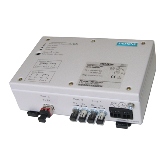
7XV5461-0Bx00 Deutsch Maßbilder ab Hardwareausgabestand /DD L ≥ 188 13,5 Port 3 Port 2 Port 1 115-250VAC / 24-250VDC Hinweis: Bitte beachten Sie, dass es kleine Unterschiede in den Abmessungen bei Ge- räten ab Hardwareausgabestand /DD gegenüber Geräten bis einschließlich Hardwareausgabestand /CC gibt. - Page 38 Deutsch 7XV5461-0Bx00 C53000-B1174-C173-5...
- Page 39 7XV5461-0Bx00 English Contents Statement of Conformity ....................40 Notes and Warnings ......................40 Unpacking and Re-packing ..................... 42 Storage and Transport ....................42 Application ........................43 Features .......................... 46 Function .......................... 47 Interfaces and Connections .................... 48 Connection Notes ......................50 Installation Notes ......................
-
Page 40: Statement Of Conformity
This conformity has been proved by tests performed according to Article 10 of the Council Directive in agreement with the generic standards EN 61000-6-2 and EN 61000-6-4 (for EMC directive) and with the standards EN 60255-6 (for low-voltage directive) by Siemens The device is designed and manufactured for application in industrial environment. - Page 41 7XV5461-0Bx00 English Warning! Hazardous voltages are present in this electrical equipment during operation. Non-observance of the safety rules can result in severe personal injury or property damage. Only qualified personnel shall work on and around this equipment after becoming thoroughly familiar with all warnings and safety notices of this booklet as well as with the applicable safety regulations.
-
Page 42: Unpacking And Re-Packing
English 7XV5461-0Bx00 Unpacking and Re-packing When dispatched from the factory, the equipment is packed in accordance with the guidelines laid down in IEC 60255-21 which specify the impact resistance of packaging. This packing shall be removed with care, without force and without the use of inappropriate tools. -
Page 43: Application
7XV5461-0Bx00 English Application The wide area fibre-optic repeater (FO-Repeater) is a universally applicable device intended for optical long-distance communication in the specified transmission band width. It serves to transfer serial optical signals over long distances using single- and multimode fibre. Via the serial inputs / outputs port 1 and port 2, synchronous and asynchronous signals are transmitted. - Page 44 English 7XV5461-0Bx00 Repeater Repeater Remote connection via single- or 7XV5461 7XV5461 multimode fibre optical optical optical optical Port 3 Port 2 BST*) Port 3 Port 2 BST*) Port 1 Port 1 Fibre-optic cable Multimode fibre 62.5/125 µm, Multimode fibre 50/125 µm optical optical Singlemode fibre 9/125 µm...
- Page 45 Modem 7XV58xx System modem RS232 7XV58xx Mini Star Coupler 7XV5450-0BA00 1) Multimode fibre with ST plugs Further devices on both sides (6XV8100) or converters Mini Star Coupler SIEMENS SIPROTEC SIEMENS SIPROTEC SIEMENS SIPROTEC SIEMENS SIPROTEC ERROR ERROR ERROR ERROR 7XV5450-0BA00 L1 402,1A Max450.1A...
-
Page 46: Features
English 7XV5461-0Bx00 Features The FO-Repeater has the following features: Two independent optical input ports (port 1, port 2) for connection of multimode fibres with ST plugs. To port 1 and port 2: Transmission of synchronous and asynchronous signals (data) in the range of 300 bit/s to 4.096 Mbit/s if singlemode fibres are connected to port 3, in the range of 300 bit/s to 1.5 Mbit/s if multimode fibres are connected to port 3. -
Page 47: Function
7XV5461-0Bx00 English Function Grounding screw Error Port 1 Data Port 2 Data Internal Logic Power On GOK (DR) Reset/Echo Mode Port 1 Port 3 Port 2 Figure 4 Hardware structure of the FO-Repeater (only one interface is available at port 3 of bidirectional FO-Repeaters) The FO-Repeater multiplexes data received on port 1 and port 2 to port 3. -
Page 48: Interfaces And Connections
English 7XV5461-0Bx00 A contact output (relay contact, changeover contact) generates a “device ready” signal (GOK = DR). The DR relay picks up (active state) if: the auxiliary supply voltage is applied, the device works correctly and the communication on port 3 is undisturbed. The DR relay drops off (inactive state) if any of the conditions mentioned above are not fulfilled. - Page 49 7XV5461-0Bx00 English The following interfaces and connections are located on the device side (Figure 5): Port 3: This fibre-optic interface serves for the connection of a second FO-Repeater via a remote connection. Via this interface, serial signals are transmitted over the range of max. 4 km to max.
-
Page 50: Connection Notes
English 7XV5461-0Bx00 Connection Notes Screw-type terminals on terminal blocks The device has the following terminal blocks (Figure 6): Terminal block for DR signal output GOK: 3-pole, Terminal block for power supply U 2-pole. The slot screws of the screw-type terminals are to be loosened and tightened with a screwdriver (0.3 x 3.5 or 0.6 x 3.5). - Page 51 7XV5461-0Bx00 English Fibre-optic (ST plug) The fibre-optic connections for port 1 and port 2 (Figure 7) are provided with cover caps to prevent the ingress of dirt into the ports. They are always to be mounted if no fibre-optic connection is used. The caps can be removed after having turned them 90° to the left. Warning! Do not look into the fibre-optic elements!
- Page 52 English 7XV5461-0Bx00 6.25 19.7 Dimensions in mm SFF connector Figure 9 Duplex LC connection Fibre-optic connector type: Duplex LC-connector (IEC 61754 20 standard) Necessary fibre type: singlemode fibre: 9/125 µm multimode fibre: 62.5/125 µm and 50/125 µm λ = approx. 1310 nm or 1550 nm Wave length: Permissible bending radius: for indoor cables: r...
- Page 53 7XV5461-0Bx00 English Attenuator If the devices 7XV5461-0Bx00 listed in table 1 are used for the communication over distances (s) shorter than specified in the technical data, the transmitting power must be reduced via optical attenuators (see Figure 11). Figure 11 Attenuator, Order no. 7XV5107-0AA00 Table 1 Using attenuators for shorter transmission links Attenuator...
-
Page 54: Installation Notes
English 7XV5461-0Bx00 Installation Notes Before starting with the installation, make sure that the following accessories are available: The manual for the device to be connected. Two fibre-optic cables. ST plugs must be provided on the connection side of the repeater. The other side depends on the connector type of the end device. - Page 55 7XV5461-0Bx00 English If the devices 7XV5461-0Bx00 are used for the communication over distances shorter than specified in the technical data (listed in table 1), the transmitting power must be reduced via optical attenuators (see Figure 11). For mounting the attenuators remove their protective caps. Plug one attenuator each, with the ratchet lever pointing upward, into the Tx and Rx connections of port 3.
-
Page 56: Commissioning
English 7XV5461-0Bx00 Commissioning Note: The FO-Repeater requires no setting. Once all necessary connections have been made, the device is immediately ready for operation. Test Mode Note: For the test mode, the FO-Repeater has to be connected to the end device as shown in Figure 11. - Page 57 7XV5461-0Bx00 English Settings in the protection device In the SIPROTEC 4 protection devices 7SD52, 7SD610, 7SA6 or 7SA52, the protection interface that controls the communication with the opposite protection device must be configured as “existing”. The fibre-optic direct connection must be set in both devices. The transmission time difference in transmit and receive direction can be set to 0, as no significant runtime delay occurs due to the repeater.
-
Page 58: Technical Data
English 7XV5461-0Bx00 Technical Data Power supply Voltage supply with wide area power supply unit DC voltage Rated voltage U DC 24 V to DC 250 V Permissible voltage ranges DC 19 V to DC 300 V Power consumption 3.5 W at DC 24 V Superimposed AC voltage, ≤12 % of auxiliary voltage, IEC 60255-11 peak-peak... - Page 59 7XV5461-0Bx00 English Port 1, Port 2 820 nm interface – Fibre-optic connector type ST plug λ = 820 nm – Optical wave length – Baud rate 300 bit/s to 1.5 Mbit/s (for reach max. 4 km, max. 8 km at Port 3 via multimode fibre 300 bit/s to 4.096 Mbit/s (for reach max.
- Page 60 English 7XV5461-0Bx00 Reach 4 km: – Path attenuation With multimode fibre, the light of the wave length λ = 1310 nm is anticipated with an optical signal attenuation of 2.5 dB/km. λ = 1310 nm – Optical wave length min. max.
- Page 61 7XV5461-0Bx00 English Reach 8 km: – Path attenuation With multimode fibre, the light of the wave length λ = 1310 nm is anticipated with an optical signal attenuation of 2.5 dB/km. λ = 1310 nm – Optical wave length min. max.
- Page 62 English 7XV5461-0Bx00 Remote connection interface for connection of singlemode fibre – Fibre-optic connector type Duplex LC-connector, SFF (IEC 61754 20 standard) – Protocol Full duplex – Baud rate 155 Mbit/s – Receiver coupling – Laser class I acc. to EN 60825-1/-2 for use of FO 9/125 µm fibre Reach 24 km: –...
- Page 63 7XV5461-0Bx00 English Reach 100 km: – Path attenuation With singlemode fibre, the light of the wave length λ = 1550 nm is anticipated with an optical signal attenuation of 0.22 dB/km. λ = 1550 nm – Optical wave length min. max.
- Page 64 English 7XV5461-0Bx00 Remote connection interface for bidirectional connection to singlemode fibre – Fibre-optic connector type Single LC-connector, SFF (IEC 61754-20 standard) – Protocol Full duplex – Baud rate 155 Mbit/s – Receiver coupling – Laser class 1 acc. to EN 60825-1/-2 for use of glass fibre 9/125 µm Reach 40 km: –...
- Page 65 7XV5461-0Bx00 English Electrical Tests Specifications Standards: IEC 60255 (Product Standards) ANSI/IEEEC37.90.0,.C37.90.0.1, C37.90.0.2 DIN 57435 Part 303 See also standards for individual tests Insulation Tests Standards: IEC/EN 61010-1, IEC 60255-5 and IEC 60870-2-1 – High Voltage Test (routine test) DC 3.5 kV only power supply and GOK –...
- Page 66 English 7XV5461-0Bx00 – Irradiation with HF Field, single frequencies IEC 60255-22-3, IEC 61000-4-3, Class III 10 V/m amplitude-modulated 80; 160; 450; 900 MHz; 80 % AM 1 kHz; duty cycle > 10 s pulse-modulated 900 MHz; 50 % PM, repetition frequency 200 Hz –...
- Page 67 7XV5461-0Bx00 English EMC Tests For Noise Emission (Type Test) Standard: EN 61000-6-3 (Generic Standard) – Radio Noise Voltage and Current 150 kHz to 30 MHz to Lines Limit Class B IEC-CISPR 22 – Radio Noise Field Strength 30 MHz to 1000 MHz IEC-CISPR 22 Limit Class B –...
- Page 68 English 7XV5461-0Bx00 Vibration and Shock Stress During Transport Standards: IEC 60255-21 and IEC 60068-2 – Vibration Sinusoidal 5 Hz to 8 Hz: ±7.5 mm Amplitude IEC 60255-21-1, Class 2 IEC 60068-2-6 8 Hz to 150 Hz: 2 g acceleration Frequency sweep rate 1 Octave/min 20 cycles in 3 orthogonal axes.
- Page 69 7XV5461-0Bx00 English Humidity yearly average ≤ 75 % relative humidity; Admissible humidity conditions on 56 days per year up to 93 % relative humidity; during operation, condensation not permissible! All devices shall be installed so that they are not exposed to direct sunlight, nor subject to great fluctuations in temperature that may cause condensation to occur.
- Page 70 English 7XV5461-0Bx00 Ordering Information Wide Area FO-Repeater Name Order Number Wide Area FO-Repeater 7 X V 5 4 6 1 - 0 B Connection of two serial, optical inputs with ST plug for 62.5/125 µm multimode fibre up to 1.5 km of 300 bit/s to 4.096 Mbit/s (single mode) or of 300 bit/s to 1.5 Mbit/s (multi mode) Wide area power supply DC: 24 V to DC: 250 V,...
- Page 71 7XV5461-0Bx00 English Name Order Number Optical 1550 nm output with LC-connectors for 9/125 µm singlemode fibre for distances of up to max. 170 km permissible optical link signal 43 dB (for transmission links < 100 km, the two attenuators (one attenuator is contained in the scope of supply of every device) must necessarily be connected to port 3) Optical bidirectional input/output with:...
-
Page 72: Dimensioned Drawings Up To Hardware Version /Cc
English 7XV5461-0Bx00 Dimensioned drawings up to hardware version /CC L ≥ 188 Wall-mounted standard mounting rail not included in the scope of delivery Crosstip screw Deblocking Dimensions in mm ) Minimum length of standard mounting rail ) Dimensional drawing applies to standard mounting rail acc. to IEC / EN 60715; 35 × 7.5 Figure 14 Dimensions of the FO-Repeater up to hardware version /CC C53000-B1174-C173-5... -
Page 73: Dimensioned Drawings From Hardware Version /Dd
7XV5461-0Bx00 English Dimensioned drawings from hardware version /DD L ≥ 188 13.5 Port 1 Port 3 Port 2 115-250VAC / 24-250VDC Note: Please note that there are minor differences in the dimensions of devices from the hardware version /DD as compared with devices up to the hardware version /CC. - Page 74 English 7XV5461-0Bx00 C53000-B1174-C173-5...
- Page 75 7XV5461-0Bx00 C53000-B1174-C173-5...
- Page 76 All Rights are reserved in the event of the grant of a patent or registration of a utility model or Subject to technical alteration design. Siemens Aktiengesellschaft C53000-B1174-C173-5 Bestell-Nr./Order No.: Bestellort/Available from: PTD EA Bln W5 AG 0408 0.1 FO 76 De-En...
Need help?
Do you have a question about the 7XV5461-0B 00 Series and is the answer not in the manual?
Questions and answers