
Related Manuals for Siemens 7XV5452-0AA00


Summary of Contents for Siemens 7XV5452-0AA00
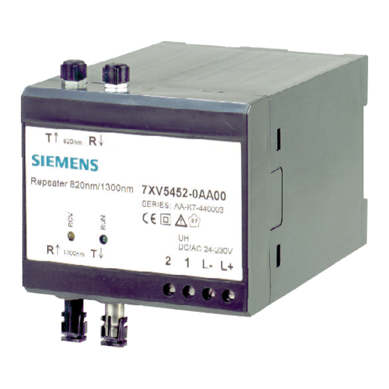
- Page 1 Repeater 820nm - 1300nm 7XV5452-0AA00 for multi mode fibre Operating Instructions...
-
Page 2: Table Of Contents
If further information is desired or in case special problems should arise, which are not treated adequately in this document, it is possible to obtain additional details from the local Siemens office or from the addresses stated in the back of this manual. - Page 3 QUALIFIED PERSONNEL Explanation of symbols used: Tampering with the device/system or noncompliance with the safety notices given in this manual may cause severe bodily injury or property Read the operating instructions; damage. Therefore any interventions on the device/system may only be performed by adequately qualified personnel.
-
Page 4: Operating Instructions
820 nm cable either FSMA for multimode fibre. Delivery of the 820 nm/1300 nm converter: 820 nm interface with FSMA connectors: 7XV5452-0AA00 Attention ! In the transmission of serial protocols like IEC 60870-5-103, IEC61850-5-101, DIGSI, Modbus, DNP3 etc. -
Page 5: Technische Daten
Technische Daten Optical 820 nm Interface Optical inputs / outputs 1 transmitter, 1 receiver Mechanical Design FO connector FSMA (plastic protective caps) Housing Plastic, EG90 see dimensional drawings Dimensions Weight approx. 250 g Degree of protection acc. to EN60529 Housing IP 51 plastic Data flow indicator none... - Page 6 Optical 1300 nm Interface 1 transmitter, 1 receiver Insulation Tests only 50/125 µm or 62,5/125 µm Delivery state: EN61010 multimode fiber Light OFF in idle state IEC 255-5: ANSI/IEEE C37.90.0 (attenuation 2-5 dB/km) Transmitter : HFBR 1315M Optical inputs / outputs Receiver : HFBR 2315M Voltage test (routine test) DC 5.25 kV / 1 s...
- Page 7 Electromagnetic Compatibility Radiated RF immunity, 10 V/m; 900 MHz; repetition pulse-modulated frequency 200 kHz; Tests IEC 1000-4-3 ED 50 % or ED 100 % Standard: EN 50081-1 150 kHz bis 30 MHz ENV 50140 / ENV50204, Class III Immunity to radio interference voltage on lines (auxiliary power Immunity to fast transient bursts On auxiliary power lines...
- Page 8 Mechanical Tests Vibration and shock test in transport Vibration and shock test in stationary use Vibration sinusoidal IEC 255-21-1, Class 1 IEC 68-2-6 5 Hz to 8 Hz: ± 7.5 mm Vibration IEC 255-21-1, Class 1 sinusoidal amplitude; IEC 68-2-6 10 Hz to 60 Hz: ±...
-
Page 9: Description Of The Functional Unit
Description of the Functional Unit Climatic Tests Recommended operating The housed signal converter is a hard-wired and tested functional unit. temperature range -5°C bis +55°C It is provided with a snap-on mounting device for a 35 mm DIN EN 50022 rail and with screw-type terminals for safe connection of the Permissible operating -20°C bis +70°C auxiliary power supply. -
Page 10: Terminal Assignment
Terminal Assignment 1.4.2 Switch Positions The DIP switches can be actuated from outside. Assignment Symbol X2, Pin 1 Power supply pin 1 (L+) DC: L+ AC: L Location of DIP switches: Down view X2, Pin 2 Power supply pin 2 (L-) DC: L- AC: N X5, Pin 1... -
Page 11: Applications
1.4.3 Applications L2 402,1A Max450.1A L2 402,1A Max450.1A L2 402,1A Max450.1A L2 402,1A Max450.1A L3 402,1A Max450.1A L3 402,1A Max450.1A L3 402,1A Max450.1A L3 402,1A Max450.1A L2 402,1A Max450.1A L2 402,1A Max450.1A L3 402,1A Max450.1A L3 402,1A Max450.1A 7XV5653-0AA00 Binary transmission Binary transmission RS232 RS232... -
Page 12: Dimension Drawings
1300 nm ST-Multi Mounting and Operation Warning ! When operating electrical devices, certain parts of these devices are necessarily under dangerous tension. Therefore, noncompliance with 7XV5452-0AA00 Repeater 820nm/1300nm SERIES: AA-K7-440005 the safety notices may cause severe bodily injury or property damage. - Page 13 Mounting Warning ! • The unit should be mounted at a location that is free of vibrations. The permissible ambient temperature (recommended or permissible operating temperature) must not be exceeded (see With stranded conductors, insulated end sleeves must be used Technical Data).
-
Page 14: Settings
Inbetriebnahme Settings • Check if the operating data correspond to the values stated on the All settings on the signal converter can be made from outside by means rating plate. of a DIL switch. It is not necessary to open the housing. •... - Page 15 Please address remarks and questions on this product to: Siemens AG Power Transmission and Distribution Protection and Substation Control Systems Postbox 4806 D-90026 Nürnberg Germany Phone +49 (0) 911 433-7028 +49 (0) 911 433-8301 Order No..: G34924-K2110-U1-A1 Order: G340B Printed in Germay...
Need help?
Do you have a question about the 7XV5452-0AA00 and is the answer not in the manual?
Questions and answers