Table of Contents
Advertisement
Quick Links
Advertisement
Table of Contents
Troubleshooting

Related Manuals for ITT Goulds Pumps NM 3196 i-FRAME


Summary of Contents for ITT Goulds Pumps NM 3196 i-FRAME
- Page 1 Installation, Operation, and Maintenance Manual Model NM 3196 i-FRAME...
-
Page 3: Table Of Contents
Table of Contents Table of Contents 1 Introduction and Safety ............................ 5 1.1 Introduction..............................5 1.1.1 Requesting other information ......................5 1.2 Safety ................................ 5 1.2.1 Safety terminology and symbols ..................... 6 1.2.2 Environmental safety........................7 1.2.3 User safety ............................7 1.3 Product warranty ............................. - Page 4 Table of Contents 4.6.1 General piping checklist ........................ 45 4.6.2 Suction-piping checklist......................... 48 4.6.3 Discharge piping checklist......................50 5 Commissioning, Startup, Operation, and Shutdown ................... 52 5.1 Preparation for startup..........................52 5.2 Remove the coupling guard ........................53 5.3 Check the rotation ........................... 55 5.4 Impeller-clearance check ........................
- Page 5 7.3 Assembly troubleshooting ........................131 8 Parts List and Cross-Sectionals ........................133 8.1 Parts list..............................133 9 Other Relevant Documentation or Manuals....................139 9.1 For additional documentation ........................ 139 10 Local ITT Contacts ............................140 Model NM 3196 i-FRAME Installation, Operation, and Maintenance Manual...
- Page 6 Table of Contents 10.1 Regional offices........................... 140 Model NM 3196 i-FRAME Installation, Operation, and Maintenance Manual...
-
Page 7: Introduction And Safety
For instructions, situations, or events that are not consid- ered in this manual or in the sales documents, please contact the nearest ITT representative. Always specify the exact product type and serial number when requesting technical information or spare parts. -
Page 8: Safety Terminology And Symbols
Risk of injury and/or property damage. Operating a pump in an inappropriate application can cause over pressurization, overheating, and/or unstable operation. Do not change the service application without the approval of an authorized ITT representative. 1.2.1 Safety terminology and symbols... -
Page 9: Environmental Safety
WARNING: If the product has been contaminated in any way, such as from toxic chemicals or nuclear radi- ation, do NOT send the product to ITT until it has been properly decontaminated and advise ITT of these conditions before returning. - Page 10 1.2 Safety • Always keep the work area clean. • Pay attention to the risks presented by gas and vapors in the work area. • Avoid all electrical dangers. Pay attention to the risks of electric shock or arc flash hazards. •...
- Page 11 1.2 Safety • Make sure that the product cannot roll or fall over and injure people or damage property. • Make sure that the lifting equipment is in good condition. • Use a lifting harness, a safety line, and a breathing device as required. •...
-
Page 12: Product Warranty
All service and repair work is done by ITT-authorized personnel. • Genuine ITT parts are used. • Only Ex-approved spare parts and accessories authorized by ITT are used in Ex-approved prod- ucts. Limitations The warranty does not cover faults caused by these situations: •... - Page 13 Compliance is fulfilled only when you operate the unit within its intended use. Do not change the condi- tions of the service without the approval of an ITT representative. When you install or maintain explosion proof products, always comply with the directive and applicable standards (for example, IEC/EN 60079-14).
- Page 14 1.4 Ex Considerations and Intended Use includes any modification to the equipment or use of parts not provided by ITT Goulds Pumps. If there is any question regarding the intended use of the equipment, please contact an ITT Goulds representative before proceeding.
- Page 15 1.4 Ex Considerations and Intended Use • Motor load readings • Temperature detectors • Bearing monitors • Leak detectors • PumpSmart control system WARNING: • When pumping unit is installed in a potentially explosive atmosphere, the instructions af- ter the Ex symbol must be followed. Personal injury and/or equipment damage may occur if these instructions are not followed.
- Page 16 If the equipment is Ex certified and the listed temperature exceeds the applicable value shown in Table 1 under SAFETY, then that temperature is not valid. Should this situation occur, please consult with your ITT/Goulds representative. • Cooling systems, such as those for bearing lubrication, mechanical seal systems, etc., where provided, must be operating properly to prevent excess heat generation, sparks and premature failure.
- Page 17 In plants or pumps with cathodic corrosion protection, a small current constantly flows through the construction. This is not permissible on the complete pump or partially-as- sembled machinery without further precautions being taken. ITT should be consulted in this context.
-
Page 18: Transportation And Storage
2 Transportation and Storage 2 Transportation and Storage 2.1 Inspect the delivery 2.1.1 Inspect the package Inspect the package for damaged or missing items upon delivery. Note any damaged or missing items on the receipt and freight bill. File a claim with the shipping company if anything is out of order. If the product has been picked up at a distributor, make a claim directly to the distributor. - Page 19 2.2 Transportation guidelines Table 2: Methods Pump type Lifting method Bare pump without lifting handles Use a suitable sling attached properly to solid points like the casing, the flang- es, or the frames. A bare pump with lifting handles Lift the pump by the handles. A base-mounted pump Use slings under the pump casing and the drive unit, or under the base rails.
- Page 20 2.2 Transportation guidelines Figure 5: Example of a proper lifting method NOTICE: Do not use this method to lift a Polyshield ANSI Combo with the pump and motor mounted. These items are not designed to handle the heavy weight of the Polyshield system. Doing so may result in equipment damage.
-
Page 21: Storage Guidelines
2.3 Storage guidelines Figure 7: Example of a proper lifting method with a strap secured around the frame adapter Figure 8: Example of offset overhead motor mount pump proper lifting method 2.3 Storage guidelines 2.3.1 Pump storage requirements Storage requirements depend on the amount of time that you store the unit. The normal packaging is designed only to protect the unit during shipping. -
Page 22: Frostproofing
2.3 Storage guidelines Treat bearing and machined surfaces so that they are well preserved. Refer to drive unit and coupling manufacturers for their long-term storage procedures. 2.3.2 Frostproofing Table 3: Situations when the pump is or is not frostproof Situation Condition Operating The pump is frostproof. -
Page 23: Product Description
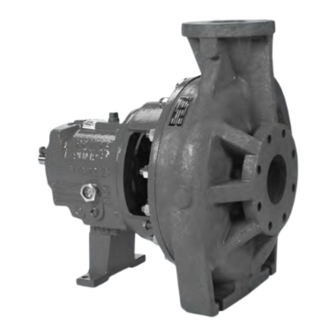
3 Product Description 3 Product Description 3.1 General description NM 3196 The NM 3196 is a horizontal overhung, open impeller, centrifugal pump. This pump is ANSI B73.1 com- pliant. It is made of a fiber-reinforced vinylester to handle severe corrosives. The model is based on 2 power ends and 13 hydraulic sizes. -
Page 24: Part Description Nm 3196
Use of equipment unsuitable for the environment can pose risks of ignition and/or explosion. Ensure the pump driver and all other auxiliary components meet the required area classifica- tion at the site. If they are not compatible, do not operate the equipment and contact an ITT representative before proceeding. -
Page 25: General Description I-Alert® Equipment Health Monitor
3.2 General description i-ALERT® Equipment Health Monitor • fully open • screwed onto the shaft • made of fiber-reinforced vinylester cast on an insert made of Hastelloy C. The insert provides threads and the support and rigidity needed to mount the impeller. The threads are sealed from the pumped liquid by a PTFE O-ring. -
Page 26: Nameplate Information
- and - resources/literature/ IOMs, https://www.i-alert.com/ or your local ITT Goulds Pumps Sales Rep. Alarm mode The condition monitor enters alarm mode when either vibration or temperature limits are exceeded over two consecutive readings within a user defined period. Alarm mode is indicated with red flashing LED. - Page 27 3.3 Nameplate information Nameplate Description Bearing frame Provides information about the lubrication system used. If applicable, your pump unit might have an Ex nameplate affixed to the pump, the baseplate, or the discharge head. The nameplate provides information about the Ex specifications of this pump.
- Page 28 3.3 Nameplate information Nameplate field Explanation MAX. DIA. Maximum impeller diameter Rated pump flow, in cubic meters per hour M HD Rated pump head, in meters Rated pump speed, in revolutions per minute MOD. Pump model SIZE Size of the pump STD.
- Page 29 Use of equipment unsuitable for the environment can pose risks of ignition and/or explosion. Ensure the pump driver and all other auxiliary components meet the required area classifica- tion at the site. If they are not compatible, do not operate the equipment and contact an ITT representative before proceeding.
-
Page 30: Installation
Electrical connections must be made by certified electricians in compliance with all inter- national, national, state and local regulations. • Supervision by an authorized ITT representative is recommended to ensure proper instal- lation. Improper installation may result in equipment damage or decreased performance. 4.1.1 Pump location guidelines... -
Page 31: Foundation Requirements
4.1 Pre-installation 4.1.2 Foundation requirements Precautions WARNING: Risk of serious injury or death in Ex-classified environments. If the pump is a Model NM3171, NM3196, 3198, CV3198, 3298, V3298, SP3298, 4150, 4550, or 3107, ignition due to static electric discharge is possible from plastic parts that are not properly grounded. If the pumped fluid is non-conductive, drain and flush the pump with a conductive fluid under conditions that will not allow for a spark to be released to the atmosphere. -
Page 32: Baseplate-Mounting Procedures
4.2 Baseplate-mounting procedures J-type bolts Item Description Baseplate Shims or wedges Foundation Bolt Figure 18: J-type bolts 4.2 Baseplate-mounting procedures 4.2.1 Prepare the baseplate for mounting Remove all the attached equipment from the baseplate. Clean the underside of the baseplate completely. If applicable, coat the underside of the baseplate with an epoxy primer. -
Page 33: Install The Baseplate Using Jackscrews
4.2 Baseplate-mounting procedures Shims or wedges Figure 19: Top view Shims or wedges Figure 20: Side view Lower the baseplate carefully onto the foundation bolts. Put the machinist's levels across the mounting pads of the driver and the mounting pads of the pump. - Page 34 4.2 Baseplate-mounting procedures Cut the plates from the bar stock and chamfer the edges of the plates in order to reduce stress concentrations. Put the plates between the jackscrews and the foundation surface. Use the four jackscrews in the corners in order to raise the baseplate above the foundation. Make sure that the distance between the baseplate and the foundation surface is between 19 mm | 0.75 in.
- Page 35 4.2 Baseplate-mounting procedures Item Description Machinist's levels Driver's mounting pads Foundation bolts Jackscrews Grout hole Pump's mounting pads Figure 22: Level driver mounting pads Turn the center jackscrews down so that they rest on their plates on the foundation surface. Level the pump mounting pads: NOTICE: Remove all dirt from the mounting pads in order to ensure that the correct leveling is achieved.
-
Page 36: Install The Baseplate Using Spring Mounting
4.2 Baseplate-mounting procedures Check that the driver's mounting pads are level and adjust the jackscrews and the foundation bolts if necessary. The correct level measurement is a maximum of 0.167 mm/m | 0.002 in./ft . 4.2.4 Install the baseplate using spring mounting NOTICE: The spring-mounted baseplate is designed only to support piping loads from thermal expan- sion. -
Page 37: Install The Baseplate Using Stilt Mounting
4.2 Baseplate-mounting procedures Upper jam nut Follower Washer Foundation pads Spring Upper adjusting nut Spring stud Figure 24: Example of an installed spring assembly 4.2.5 Install the baseplate using stilt mounting NOTICE: The stilt-mounted baseplate is not designed to support static piping loads. Ensure that the suc- tion and discharge piping are supported individually. - Page 38 4.2 Baseplate-mounting procedures Lower the baseplate so that the stilts fit into the foundation cups. Level the baseplate and make the final height adjustments: Loosen the upper jam nuts and adjusting nuts. Adjust the height and level the baseplate by moving the lower adjusting nuts. When the baseplate is level, tighten the top adjusting nuts.
-
Page 39: Baseplate-Leveling Worksheet
4.2 Baseplate-mounting procedures 4.2.6 Baseplate-leveling worksheet Level measurements 1)____________________ 2)____________________ 3)____________________ 4)____________________ 5)____________________ 6)____________________ 7)____________________ 8)____________________ 9)____________________ 10)___________________ 11)___________________ 12)___________________ 13)___________________ 14)___________________ 15)___________________ 16)___________________ 17)___________________ 18)___________________ Model NM 3196 i-FRAME Installation, Operation, and Maintenance Manual... -
Page 40: Install The Pump, Driver, And Coupling
4.3 Install the pump, driver, and coupling 4.3 Install the pump, driver, and coupling Mount and fasten the pump on the baseplate. Use applicable bolts. Mount the driver on the baseplate. Use applicable bolts and hand tighten. Install the coupling. See the installation instructions from the coupling manufacturer. -
Page 41: Permitted Indicator Values For Alignment Checks
The correct tolerances must be used. Failure to do so can result in misalignment. Contact ITT for further information. When dial indicators are used to check the final alignment, the pump and drive unit are correctly aligned when these conditions are true: •... -
Page 42: Attach The Dial Indicators For Alignment
4.4 Pump-to-driver alignment Guideline Explanation Check the alignment again after any mechanical adjustments. This corrects any misalignments that an adjust- ment may have caused. 4.4.4 Attach the dial indicators for alignment You must have two dial indicators in order to complete this procedure. Attach two dial indicators on the pump coupling half (X): Attach one indicator (P) so that the indicator rod comes into contact with the perimeter of the driver coupling half (Y). - Page 43 4.4 Pump-to-driver alignment Shims Figure 27: Side view of an incorrect vertical alignment Repeat the previous steps until the permitted reading value is achieved. 4.4.5.2 Perform angular alignment for a horizontal correction Set the angular alignment indicator (A) to zero on left side of the driver coupling half (Y), 90° from the top-center position (9 o’clock).
- Page 44 The specified permitted reading values are valid only at operating temperature. For cold set- tings, other values are permitted. The correct tolerances must be used. Failure to do so can result in misalignment. Contact ITT for further information. 4.4.5.4 Perform parallel alignment for a horizontal correction Refer to the alignment table in "Permitted indicator values for alignment checks"...
-
Page 45: C-Face Adapter
The specified permitted reading values are valid only at operating temperature. For cold set- tings, other values are permitted. The correct tolerances must be used. Failure to do so can result in misalignment. Contact ITT for further information. 4.4.5.5 Perform complete alignment for a vertical correction A unit is in complete alignment when both the angular indicator (A) and the parallel indicator (P) do not vary by more than 0.05 mm | 0.002 in. -
Page 46: Grout The Baseplate
4.5 Grout the baseplate Illustration Figure 31: Example of the C-face adapter (340) Alignment requirements When you use a C-face adapter, you do not have to align the shaft. The rabbeted fittings of the drive unit to the adapter and the adapter to the bearing frame automatically align the shaft to within the specified limits. -
Page 47: Piping Checklists
4.6 Piping checklists Item Description Baseplate Shims or wedges Grout Foundation Sleeve Bolt Figure 32: Pour grout into baseplate Fill the remainder of the baseplate with grout, and allow the grout to set for at least 48 hours. Item Description Baseplate Grout Foundation... - Page 48 4.6 Piping checklists system, including those from the thermal expansion of the piping, must not exceed the limits of the pump. • Risk of serious personal injury or property damage. Fasteners such as bolts and nuts are critical to the safe and reliable operation of the product. Ensure appropriate use of fasten- ers during installation or reassembly of the unit.
- Page 49 4.6 Piping checklists Check Explanation/comment Checked If the pump handles liquids at elevat- This helps to prevent misalignment due to linear expansion of ed temperatures, make sure that the the piping. expansion loops and joints are prop- erly installed. Make sure that all piping compo- —...
-
Page 50: Suction-Piping Checklist
4.6 Piping checklists • Ensure that all fasteners are properly tightened and that there are no missing fasteners. 4.6.2 Suction-piping checklist Performance curve reference Net positive suction head available (NPSH ) must always exceed NPSH required (NPSH ) as shown on the published performance curve of the pump. - Page 51 4.6 Piping checklists Liquid source below the pump Check Explanation/comment Checked Make sure that the suction piping is free This helps to prevent the occurrence of air and cavita- from air pockets. tion in the pump inlet. Check that the suction piping slopes up- —...
-
Page 52: Discharge Piping Checklist
4.6 Piping checklists Example: Suction piping equipment Correct Incorrect Suction pipe sloping upwards from liquid source Air pocket, because the eccentric reducer is not used and because the suction piping does not Long-radius elbow slope gradually upward from the liquid source Strainer Foot valve Eccentric reducer with a level top... - Page 53 4.6 Piping checklists Check Explanation/comment Checked If quick-closing valves are installed in the This protects the pump from surges and water hammer. system, check that cushioning devices are used. Example: Discharge piping equipment Correct Incorrect Check valve (incorrect position) Bypass line The isolation valve should not be positioned be- Shut-off valve tween the check valve and the pump.
-
Page 54: Commissioning, Startup, Operation, And Shutdown
5 Commissioning, Startup, Operation, and Shutdown 5 Commissioning, Startup, Operation, and Shutdown 5.1 Preparation for startup WARNING: • Risk of serious physical injury or death. Exceeding any of the pump operating limits (e.g. - pressure, temperature, power, etc.) could result in equipment failure, such as explosion, seizure, or breach of containment. -
Page 55: Remove The Coupling Guard
5.2 Remove the coupling guard CAUTION: When a cartridge mechanical seal is used, ensure that the set screws in the seal locking ring are tightened and that the centering clips have been removed prior to startup. This prevents seal or shaft sleeve damage by ensuring that the seal is properly installed and centered on the sleeve. - Page 56 5.2 Remove the coupling guard Driver Remove the nut, bolt, and washers from the driver half of the coupling guard. Remove the driver half of the coupling guard: Slightly spread the bottom apart. Lift upwards. Driver-side coupling guard Annular groove Driver Remove the remaining nut, bolt, and washers from the pump half of the coupling guard.
-
Page 57: Check The Rotation
5.3 Check the rotation Item Description Annular groove Pump-side end plate Driver Pump half of the coupling guard 5.3 Check the rotation WARNING: • Starting the pump in reverse rotation can result in the contact of metal parts, heat genera- tion, and breach of containment. -
Page 58: Impeller Clearances (Nm 3196)
5.5 Impeller-clearance setting 5.4.1 Impeller clearances (NM 3196) NOTICE: Set the cold (ambient) impeller clearance according to and . Failure to do so may result in heat generation and equipment damage. Higher clearances are used above 93°C | 200°F to prevent the impeller from contacting the casing due to thermal expansion. -
Page 59: Set The Impeller Clearance - Dial Indicator Method (All Except Cv 3196, Cv 3198, And Lf 3196 Size 1X1.5-4)
5.5 Impeller-clearance setting Back clearance Front clearance Figure 34: Impeller clearance measurement 5.5.1 Set the impeller clearance - dial indicator method (all except CV 3196, CV 3198, and LF 3196 size 1x1.5-4) WARNING: Failure to disconnect and lock out driver power may result in serious physical injury or death. Always disconnect and lock out power to the driver before performing any installation or main- tenance tasks. -
Page 60: Set The Impeller Clearance - Feeler Gauge Method (All Except Cv 3196, Cv3198 And Lf 3196 Size 1X1.5-4)
5.5 Impeller-clearance setting 134A 370C 370D Figure 35: Dial indicator setting Loosen the jam nuts (423) on the jack bolts (370D) , and then back the bolts out about two turns. Tighten the locking bolts evenly (370C), bringing the bearing housing (134A) towards the frame (228) until the impeller contacts the casing. -
Page 61: Couple The Pump And Driver
5.6 Couple the pump and driver .015 370C 371A 423B 134A Figure 36: Impeller clearance setting Evenly tighten the locking bolts (370C), bringing the bearing housing (134A) towards the frame (228) until the impeller contacts the casing. Turn the shaft to ensure that there is contact between the impeller and the casing. Use a feeler gauge to set the gap between the three locking bolts (370C) and the bearing housing (134A) to the correct impeller clearance. -
Page 62: Install The Coupling Guard
5.6 Couple the pump and driver 5.6.1 Install the coupling guard WARNING: • Running a pump without safety devices exposes operators to risk of serious personal in- jury or death. Never operate a unit unless appropriate safety devices (guards, etc.) are properly installed. - Page 63 5.6 Couple the pump and driver Figure 37: Required parts De-energize the motor, place the motor in a locked-out position, and place a caution tag at the start- er that indicates the disconnect. Put the pump-side end plate in place. If the pump-side end plate is already in place, make any necessary coupling adjustments and then proceed to the next step.
- Page 64 5.6 Couple the pump and driver Item Description Annular groove Pump-side end plate Driver Pump half of the coupling guard Figure 38: Align pump end guard half with annular groove Item Description Annular groove End plate (pump end) Guard half Figure 39: Annular groove in coupling guard Place one washer over the bolt and insert the bolt through the round hole at the front end of the guard half.
- Page 65 5.6 Couple the pump and driver Figure 40: Captured hardware component assembly Install the bolt retainer over the exposed end of the bolt, and the U-Nut into the slot in the coupling guard if it was not done from the factory. Thread bolt into the U-Nut and tighten firmly.
- Page 66 5.6 Couple the pump and driver End plate Driver Figure 42: Placement of driver half of coupling guard Hand-tighten only. Repeat Steps 4 through 6 for the rear end of the coupling guard half. The hole is located on the driver-side of the coupling guard half. 10.
-
Page 67: Bearing Lubrication
5.6 Couple the pump and driver 5.6.2 Bearing lubrication WARNING: Risk of explosive hazard and premature failure from sparks and heat generation. Ensure bear- ings are properly lubricated prior to startup. NOTICE: Grease can settle in equipment left idle leaving bearings improperly lubricated. Check the greasing on a pump that has been out of service for a long period of time and re-grease if nec- essary. -
Page 68: Shaft-Sealing Options
5.7 Shaft-sealing options Brand Lubricant type Shell Turbo T 68 Sunoco Sunvis 968 Royal Purple SYNFILM ISO VG 68 Synthetic Oil 5.6.2.4 Lubricate the bearings with oil WARNING: Risk of explosive hazard and premature failure from sparks and heat generation. Ensure bear- ings are properly lubricated prior to startup. -
Page 69: Mechanical Seal Options
5.8 Install the shaft guard - if provided This model uses these types of shaft seals: • Cartridge mechanical seal • Conventional inside-component mechanical seal • Conventional outside-component mechanical seal 5.7.1 Mechanical seal options Pumps are usually shipped with mechanical seals installed. If they are not, then refer to the mechanical seal manufacturer's installation instructions. -
Page 70: Pump Priming
5.9 Pump priming Exposed rotating shaft between pump seal and bearing frame. Avoid contact and/or install proper guard- ing. If guarding is not provided with the pump, contact Goulds for price and availability of proper guard- ing. 5.9 Pump priming 5.9.1 Prime the pump with the suction supply above the pump Slowly open the suction isolation valve. -
Page 71: Other Methods Of Priming The Pump
5.10 Start the pump Item Description By-pass line Item Description Shutoff valve Discharge isolation valve Foot valve Shutoff valve Check valve From outside supply Discharge isolation valve Foot valve Check valve Figure 47: Pump priming with suction supply below pump with foot valve using bypass Figure 46: Pump priming with suction supply around check valve below pump with foot valve and an outside sup-... -
Page 72: I-Alert® Equipment Health Monitor
5.11 i-ALERT® Equipment Health Monitor • To avoid risk of equipment damage, observe the pump for vibration levels, bearing tem- perature, and excessive noise. If normal levels are exceeded, shut down the pump and resolve the issue. NOTICE: Risk of equipment damage on pure or purge-oil mist-lubricated units. Remove the viewing port plugs to verify that oil mist is flowing properly. - Page 73 5.12 Pump operation precautions • Risk of explosion and serious physical injury. Do not operate pump with blocked system piping or with suction or discharge valves closed. This can result in rapid heating and va- porization of pumpage. NOTICE: • Vary the capacity with the regulating valve in the discharge line.
-
Page 74: Shut Down The Pump
5.13 Shut down the pump 5.13 Shut down the pump WARNING: Precautions must be taken to prevent physical injury. The pump may handle hazardous and/or toxic fluids. Proper personal protective equipment should be worn. Pumpage must be handled and disposed of in conformance with applicable environmental regulations. Slowly close the discharge valve. - Page 75 5.16 Make the final alignment of the pump and driver • Refer to driver/coupling/gear manufacturer's installation and operation manuals (IOM) for specific instructions and recommendations. • Misalignment can cause decreased performance, equipment damage, and even cata- strophic failure of frame-mounted units leading to serious injury. Proper alignment is the responsibility of the installer and the user of the unit.
-
Page 76: Maintenance
6 Maintenance 6 Maintenance 6.1 Maintenance schedule Maintenance inspections A maintenance schedule includes these types of inspections: • Routine maintenance • Routine inspections • Three-month inspections • Annual inspections Shorten the inspection intervals appropriately if the pumped fluid is abrasive or corrosive or if the envi- ronment is classified as potentially explosive. -
Page 77: Bearing Maintenance
These bearing lubrication sections list different temperatures of the pumped fluid. If the pump is Ex-certified and the temperature of the pumped fluid exceeds the permitted temperature values, then consult your ITT representative. For Ex applications bearing replacement (all) is recommended after 17,500 hours of opera- tion. -
Page 78: Regrease The Grease-Lubricated Bearings
6.2 Bearing maintenance 6.2.1.1 Oil volumes Oil volume requirements This table shows the required amount of oil for oil-lubricated bearings. Frame Qts. 1400 6.2.1.2 Acceptable oil for lubricating bearings Acceptable lubricants Table 13: Acceptable lubricants Brand Lubricant type Chevron GST Oil 68 Exxon Teresstic EP 68 Mobil... -
Page 79: Lubricate The Bearings After A Shutdown Period
6.2 Bearing maintenance Make sure that the frame seals are seated in the bearing housing. If they are not, press them in place with the drains located at the bottom. Reinstall the grease-relief plugs. Wipe off any excess grease. Recheck the alignment. The bearing temperature usually rises after you regrease due to an excess supply of grease. -
Page 80: Shaft Seal Maintenance
Cartridge seals installed by the user require disengagement of the hold- ing clips prior to operation, allowing the seal to slide into place. If the seal has been installed in the pump by ITT, these clips have already been disengaged. Other mechanical seal types For other types of mechanical seals, refer to the instructions provided by the seal manufacturer for instal- lation and setting. -
Page 81: Tools Required
6.4 Disassembly • Risk of serious personal injury. Applying heat to impellers, propellers, or their retaining devices can cause trapped liquid to rapidly expand and result in a violent explosion. This manual clearly identifies accepted methods for disassembling units. These methods must be adhered to. -
Page 82: Remove The Coupling
6.4 Disassembly electric discharge is possible from plastic parts that are not properly grounded. If the pumped fluid is non-conductive, drain and flush the pump with a conductive fluid under conditions that will not allow for a spark to be released to the atmosphere. CAUTION: •... - Page 83 6.4 Disassembly 408A Figure 50: Back pull-out assembly removal (oil lubricated bearing frame) Oil analysis should be part of a preventive maintenance program that determines the cause of a fail- ure. Save the oil in a clean container for inspection. The back pull out assembly consists of all parts except the casing (100).
-
Page 84: Remove The Coupling Hub
6.4 Disassembly Figure 52: Back pull-out assembly removal (without C-face adapter) Remove the hold-down bolts of the bearing frame foot. Tighten the jackscrews evenly, using an alternating pattern, in order to remove the back pull-out as- sembly. You can use penetrating oil if the adapter to the casing joint is corroded. Remove the back pull-out assembly from the casing (100). -
Page 85: Impeller Removal
6.4 Disassembly Mark the shaft for relocation of the coupling hub during reassembly. Figure 54: Coupling hub removal 6.4.7 Impeller removal 6.4.7.1 Remove the impeller (STi, MTi) WARNING: Risk of severe physical injury or death from explosion of trapped liquid. Never use heat to re- move parts unless explicitly stated in this manual. -
Page 86: Shaft Guard Removal (If Provided)
6.4 Disassembly Repeat step 3 until the impeller becomes loose. Remove and discard the impeller O-ring (412A). You will insert a new O-ring during reassembly. 412A Figure 56: O-ring for models 3196, HT 3196, NM 3196, 3198, CV 3198 and 3796 If the impeller cannot be removed by the previous methods, cut the shaft between the gland and the frame, remove the impeller, stuffing-box cover, gland, sleeve, and shaft end as a unit. -
Page 87: Seal-Chamber Cover Removal
6.4 Disassembly 6.4.8.2 Remove the shaft guard (MTi/LTi, XLTi/i17) Remove the bolt for each shaft guard half that mounts the halves to the brackets on each side. Do not remove the clip that retains the bolt on the guard half to maintain a captive fastener. Retain each guard half with fasteners for reinstallation. - Page 88 6.4 Disassembly 370H Figure 59: Bearing housing and bearing removal Remove the shaft sleeve (126). The mechanical seal is attached to the sleeve. Loosen the set screws and slide the rotary portion off the sleeve. On the 3198, remove the PTFE sleeve: Remove the mechanical seal from the sleeve.
-
Page 89: Remove The Frame Adapter (Mti)
6.4 Disassembly 6.4.11 Remove the frame adapter (MTi) The 3198 frame adapter is not interchangeable with the adapter of any other model. Remove the dowel pins (469B) and the bolts (370B). Remove the frame adapter (108). Remove and discard the gasket (360D). You will install a new gasket during reassembly. - Page 90 6.4 Disassembly 228A 370D 370C Figure 63: Shaft assembly removal Remove the jack screws (370D) with nuts (423). Remove the bearing housing O-ring (496) and the bearings. Remove the outboard bearing retaining snap ring (361A). 370D 423 361A 168A Figure 64: Outboard bearing retaining snap ring removal Remove the bearing housing (134) and bearings (112A and 168A) from the shaft (122).
- Page 91 6.4 Disassembly NOTICE: Use force only on the inner race when pressing bearings from the shaft. Failure to do so may result in equipment damage. NOTICE: Do not reuse bearings if removed from shaft. Doing so may result in equipment damage. Re- place the bearings before reassembly.
- Page 92 6.4 Disassembly 236A 370D 253B Figure 68: Jack screw removal Remove the bearing housing O-ring (496). Remove the clamp ring screws (236A) and separate the clamp ring (253B) from the bearing hous- ing (134). You must remove the bearings before you can remove the clamp ring from the shaft. Remove the bearing housing (134) and the bearings (112A and 168A) from the shaft (122).
-
Page 93: Disassemble The Bearing Frame
6.4 Disassembly NOTICE: Use force only on the inner race when pressing bearings from the shaft. Failure to do so may result in equipment damage. NOTICE: Do not reuse bearings if removed from shaft. Doing so may result in equipment damage. Re- place the bearings before reassembly. -
Page 94: Guidelines For I-Alert® Equipment Health Monitor Disposal
6.5 Pre-assembly inspections ® 6.4.15 Guidelines for i-ALERT Equipment Health Monitor disposal Precautions WARNING: • Explosive hazard and risk of personal injury. Heating to high temperatures could cause combustion of the condition monitor. Never heat the condition monitor to temperatures in excess of 149°C | 300°F or dispose of in a fire. -
Page 95: Replacement Guidelines
6.5 Pre-assembly inspections 6.5.1 Replacement guidelines Casing check and replacement WARNING: Risk of death or serious injury. Leaking fluid can cause fire and/or burns. Inspect and ensure gasket sealing surfaces are not damaged and repair or replace as necessary. Inspect the casing for cracks and excessive wear or pitting. Thoroughly clean gasket surfaces and align- ment fits in order to remove rust and debris. - Page 96 6.5 Pre-assembly inspections Impeller areas to inspect Figure 74: Areas to inspect for wear on the 3196 impeller. Frame adapter check and replacement • Replace the frame adapter if it has cracks or excessive corrosion damage. • Make sure the gasket surface is clean. Labyrinth seal replacement Replace the labyrinth-seal O-ring if it has cuts and cracks.
-
Page 97: Shaft And Sleeve Replacement Guidelines
6.5 Pre-assembly inspections 6.5.1.1 Fastening WARNING: Risk of serious personal injury or property damage. Fasteners such as bolts and nuts are criti- cal to the safe and reliable operation of the product. Ensure appropriate use of fasteners during installation or reassembly of the unit. •... -
Page 98: Bearing-Frame Inspection
6.5 Pre-assembly inspections • Replace the shaft and sleeve if any grooves or pits are found. 6.5.3 Bearing-frame inspection Checklist Check the bearing frame for these conditions: • Visually inspect the bearing frame and frame foot for cracks. • Check the inside surfaces of the frame for rust, scale, or debris. Remove all loose and foreign ma- terial. -
Page 99: C-Face Adapter Inspection
6.5 Pre-assembly inspections 6.5.4 C-face adapter inspection Checklist • Visually inspect the C-face adapter (340) for cracks. • Check all surfaces for rust, scale, or debris and remove all loose and foreign material. • Check for corrosion or pitting. This figure shows the areas to inspect for cracks on the C-face adapter. Figure 79: C-face adapter inspection locations 6.5.5 Seal chamber and stuffing box cover inspection Checklist... -
Page 100: Bearings Inspection
6.5 Pre-assembly inspections Figure 80: NM 3196 backplate Figure 81: NM 3196 seal chamber 6.5.6 Bearings inspection Condition of bearings Do not reuse bearings. The condition of the bearings provides useful information on operating conditions in the bearing frame. Checklist Perform these checks when you inspect the bearings: •... -
Page 101: Bearing-Housing Inspection
6.6 Reassembly 6.5.7 Bearing-housing inspection Checklist • Inspect the bearing-housing (134) bore according to the bearing fits and tolerances table. • Replace the bearing housing if the dimensions exceed acceptable values. Reference: see Bearings fits and tolerances. • Visually inspect the bearing housing for cracks and pits. Checklist for specific models This table shows bearing-housing checks that are required for specific models of pump. - Page 102 6.6 Reassembly Prepare the bearing frame (228) as follows (see the illustration): Install the oil-fill plug (113A). Install the oil-drain plug (408A). Install the sight glass (319). Install the sight oiler plug (408J). Install the plug for the oil-cooler inlet (408L). Install the plug for the oil-cooler outlet (408M).
- Page 103 6.6 Reassembly Put the bearing-retaining ring (361A) onto the shaft (122). Make sure that the flat side of the ring is towards the bearing. Coat the inner surfaces of the bearings with lubricant. Put the inboard bearing (168) onto the shaft (122). The regreasable bearing has a single shield.
-
Page 104: Assemble The Rotating Element And The Bearing Frame (Sti And Mti With Duplex Bearings)
6.6 Reassembly 332A 361A 168A Figure 85: Outboard labyrinth oil-seal reassembly 10. Install the shaft assembly into the bearing frame as follows (see the illustration): Coat the outside of the bearing housing (134) with oil. Coat all the internal surfaces of the bearing frame (228) with oil. Install the shaft assembly into the bearing frame (228). - Page 105 6.6 Reassembly CAUTION: Risk of physical injury from hot bearings. Wear insulated gloves when using a bearing heater. NOTICE: Ensure that the pipe threads are clean. Apply thread sealant to the plugs and fittings. Failure to do so may result in oil leaks and equipment damage. NOTICE: There are several methods used to install bearings.
- Page 106 6.6 Reassembly The duplex bearings are mounted back-to-back. Make sure that the orientation of the bearings are correct. Inspect the shaft (122) to ensure that it is clean, dimensionally correct, and is free of nicks and burrs. Figure 88: Shaft inspection Lightly coat the bearing seating with a thin film of oil.
- Page 107 6.6 Reassembly Coat the bore of the bearing housing (134) with oil. Put the bearing housing (134) onto the shaft. Do not use force. 253B 168A 112A Figure 90: Bearing housing reassembly 10. Prepare the shaft for assembly as follows (see the illustration): Place the bearing-clamp ring (253B) onto the shaft (122).
-
Page 108: Assemble The Frame
6.6 Reassembly Install the clamp bolts (370C) in the bearing housing (134) and tighten by hand. Install the jack bolts (370D) with the locknuts (423) in the bearing housing (134) and tighten by hand. 6.6.3 Assemble the frame Support the frame assembly in a horizontal position. Check the shaft-end play by moving the shaft forward and backward by hand, and note any indica- tor movement. - Page 109 6.6 Reassembly Figure 92: Check shaft end play Check the shaft-sleeve (126) runout. Install the shaft sleeve. Thread the impeller on the shaft until hand tight. Rotate the shaft 360º. If the total indicator reading is greater than 0.051 mm | 0.002 in., then disassemble the shaft sleeve and determine the cause.
- Page 110 6.6 Reassembly Figure 93: Remove impeller and shaft sleeve Check the frame-face run-out by rotating the shaft so that the indicator measures the fit for 360º. If the total indicator reading is greater than 0.025 mm | 0.001 in., then disassemble and determine the cause.
- Page 111 6.6 Reassembly 360D 496B 370B Figure 95: Align bolt holes and dowel locations Install the dowel pins (469B) and bolts (370B). Tighten the bolts in a criss-cross pattern accord- ing to the specifications in the bolt torque values table. Rotate the shaft 360º to check the adapter fit. If the total indicator reading is greater than 0.13 mm | 0.005 in., then determine the cause and cor- rect it before you proceed.
-
Page 112: Inpro Labyrinth Oil Seal Description
6.6 Reassembly 333A Figure 97: Position labyrinth oil-seal drain slots 6.6.4 INPRO labyrinth oil seal description Description The INPRO VBXX-D Labyrinth Oil Seal consists of the rotor (1), the stator (2), and the VBX Ring (3). The rotor (1) fits over the shaft and is held in place by an elastomeric drive ring (4). The drive ring causes the rotor to turn with the shaft and provides a positive, static seal against the shaft. -
Page 113: Assemble The C-Face Adapter
6.6 Reassembly NOTICE: The edges of the keyway can be sharp. Cover the keyway with tape. Failure to do so may re- sult in damaging the o-ring and/or labyrinth seal. Lightly lube the shaft and the drive ring (4) with lubricant. Lubricant helps in the installation process. - Page 114 6.6 Reassembly Methods for sealing the shaft These sections discuss the methods that you can use to seal the shaft. • Seal the shaft with a cartridge-mechanical seal. • Seal the shaft with a conventional inside-component mechanical seal. • Seal the shaft with a conventional outside-component mechanical seal. •...
- Page 115 6.6 Reassembly 370H Figure 99: Assemble seal-chamber Check the seal-chamber cover runout. Figure 100: Check seal-chamber cover runout Rotate the indicator through 360º. If the total indicator reading is greater than 0.13 mm | 0.005 in- ches, determine the cause and correct the issue before you proceed. Install the shaft sleeve (126).
- Page 116 6.6 Reassembly 412A Figure 101: Install shaft sleeve Mark the shaft and sleeve at the face of the seal chamber. Continue the complete reassembly of the pump, except for the mechanical seal. Set the impeller clearance. Refer to the Impeller Clearance Setting section for more information. Scribe a line on the marked shaft and sleeve at the face of the seal chamber.
- Page 117 6.6 Reassembly 370H Figure 102: Seal-chamber cover or backplate installation Check the seal-chamber cover runout. Figure 103: Check seal-chamber cover runout Rotate the indicator through 360 degrees. If the total indicator reading is greater than 0.13 mm | 0.005 in., determine the cause and correct the issue before you proceed. Install the shaft sleeve (126).
- Page 118 6.6 Reassembly 412A Figure 104: Install shaft sleeve Mark the shaft and sleeve at the face of the seal chamber. Continue the complete reassembly of the pump, except for the mechanical seal. Set the impeller clearance. Refer to the Impeller clearance setting section for more information. Scribe a line on the marked shaft and sleeve at the face of the seal chamber.
- Page 119 6.6 Reassembly Assemble shaft sleeve, impeller, casing gasket and casing. (less mechanical seal). See Figure 101: Install shaft sleeve on page 114. Check Total Travel and set Impeller Front Clearance. Refer to the Impeller Clearance Setting section for more information. Scribe a line to mark the location of the cover face onto the shaft sleeve.
-
Page 120: Shaft Guard Installation (If Provided)
6.6 Reassembly 6.6.8 Shaft guard installation (if provided) 6.6.8.1 Install the shaft guard (STi) WARNING: • Running a pump without safety devices exposes operators to risk of serious personal in- jury or death. Never operate a unit unless appropriate safety devices (guards, etc.) are properly installed. -
Page 121: Install The Impeller
6.6 Reassembly 6.6.8.2 Install the shaft guard (MTi/LTi/XLTi/i17) WARNING: • Running a pump without safety devices exposes operators to risk of serious personal in- jury or death. Never operate a unit unless appropriate safety devices (guards, etc.) are properly installed. •... - Page 122 6.6 Reassembly Pump size Action STi, MTi Install the impeller (101). Use a new impeller O-ring (412A). Attach a shaft wrench and a coupling key on the shaft. When the impeller (101) makes firm contact with the sleeve (126), raise the shaft wrench (counterclockwise, viewed from the impeller end of the shaft) off of the bench and slam it down (clockwise, viewed from the impeller end of shaft).
-
Page 123: Post-Assembly Checks
6.6 Reassembly This approximates the impeller position when it is set to 0.38 mm | 0.015 in. from the casing. Per- form a final impeller adjustment after you install the impeller into the casing. Check the impeller (101) runout. Check vane tip to vane tip. If the total indicator reading is greater than 0.13 mm | 0.005 in., deter- mine the cause and correct the issue before you proceed. - Page 124 6.6 Reassembly 370C 370D Figure 110: Loosen clamp bolts and jack bolts on bearing housing Install the back pull-out assembly in the casing. Figure 111: Install back pull-out assembly Model NM 3196 i-FRAME Installation, Operation, and Maintenance Manual...
- Page 125 6.6 Reassembly Figure 112: Install back pull-out assembly Install and then hand-tighten the casing bolts (370). Refer to the bolt torque values for information on how to tighten the casing bolts. Install and tighten the casing jackscrews (418). NOTICE: Do not overtighten the casing jackscrews. Doing so may result in equipment damage. 370F Figure 113: Install and tighten casing jackscrews Reinstall the shims under the frame foot and tighten the frame foot to the baseplate.
-
Page 126: Assembly References
6.6 Reassembly Frame Total travel STi, MTi, LTi 0.76 mm to 1.65 mm | 0.030 in. to 0.065 in. 4x6-10H only 1.53 mm to 2.29 mm | 0.060 in. to 0.090 in. XLTi, i-17 1.02 mm to 2.67 mm | 0.040 in. to 0.105 in. Adjust the impeller clearance. -
Page 127: Spare Parts
6.6 Reassembly 6.6.12.2 Shaft-end play Table 22: Shaft-end play Use this table as a reference for shaft-end play values. Frame Double row bearing Duplex bearing 0.028 | 0.0011 0.018 | 0.0007 STi millimeters | inches 0.048 | 0.0019 0.025 | 0.0010 0.033 | 0.0013 0.023 | 0.0009 MTi millimeters | inches... -
Page 128: Interchangeability Drawings
6.7 Interchangeability drawings 6.7 Interchangeability drawings 6.7.1 NM 3196 interchangeability 6.8 Lubrication conversion 6.8.1 Frame lubrication conversion NOTICE: • Avoid equipment damage or decreased performance. Never mix greases of different con- sistencies (NLGI 1 or 3 with NLGI 2) or with different thickeners. For example, never mix a lithium-based grease with a polyurea based grease. -
Page 129: Convert From Greased-For-Life Or Regreaseable To Oil-Lubricated Bearings
6.8 Lubrication conversion Table 24: Lubricating-grease requirements Most pumps use Sunoco 2EP grease. High temperature units with a pumpage temperature greater than 177°C | 350° F use Mobil SCH32. This table shows which brand of grease to use when lubricating the pump. Pumpage temperature less than 177°C | 350°F Pumpage temperature greater than 177°C | 350°F NGLI consistency 2... -
Page 130: Conversion From Flood-Oil To Pure-Oil Mist
Ensure that the pipe threads are clean. Apply thread sealant to the plugs and fittings. Failure to do so may result in oil leaks and equipment damage. Consult your local ITT representative for further information on this topic. 6.8.3.1 Oil mist systems... -
Page 131: Convert From Flood Oil To Regreaseable
6.8 Lubrication conversion Figure 115: Replace two plugs (408H) with two to oil mist connectors Oil-mist systems The ITT X i-Series Power Ends accepts a variety of oil-mist systems. These are the two popular systems that you can use: •... -
Page 132: Troubleshooting
The shaft is rotating in the wrong direction. Change the rotation. The rotation must match the arrow on the bearing housing or pump casing. The foot valve or suction pipe opening is Consult an ITT representative for the proper not submerged enough. submersion depth. Use a baffle in order to eliminate vortices. -
Page 133: Alignment Troubleshooting
If this does liquid. not help, then contact your ITT representa- tive. The liquid is heavier than expected. Check the specific gravity and viscosity. The stuffing-box packing is too tight. - Page 134 7.3 Assembly troubleshooting Symptom Cause Remedy There is excessive vane-tip runout of The vane is bent. Replace the impeller. the impeller. Model NM 3196 i-FRAME Installation, Operation, and Maintenance Manual...
-
Page 135: Parts List And Cross-Sectionals
8 Parts List and Cross-Sectionals 8 Parts List and Cross-Sectionals 8.1 Parts list Table 26: Construction material and quantity Pump Material Item Part name Fiberglass Reinforced Vinylester Casing 6929 Impeller (with insert) 6929 (Insert - 1215) Frame Adapter 1013 Outboard Bearing Double row angular contact Plug - Grease Relief 2210... - Page 136 8.1 Parts list Pump Material Item Part name Fiberglass Reinforced Vinylester Mechanical Seal Material Varies Key-Coupling Steel 408A Plug−Oil Drain 2210 408H Plug−Oil Mist Connection 2210 408J Plug−Oiler 2210 408L Plug−Oil Cooler Inlet 2210 408M Plug−Oil Cooler Outlet 2210 408N Plug−Sight Glass 2210 412A...
- Page 137 8.1 Parts list Material Goulds material ASTM (UNS) code Carbon Steel 2210 A108 Gr. 1018 (G10180) 304SS 2228 A276 Type 304 (S30400) 316SS 2229 A276 Type 316 (S31600) Alloy 20 2230 B473 (N08020) 4140 Steel 2238 A434 Gr. 4140 (G41400) Cl. BC Alloy B-2 2247 B335 (N10665)
- Page 138 8.1 Parts list 113A 356A 372T 370B 361A 408W 360D 761B 497H 370C 497G 497F 370H 332A 412A 370D 423B Either 228A side 412V 408N 370F 408A 497J 408L 469B 333A 408M Figure 116: NM 3196 cross-sectional drawing Model NM 3196 i-FRAME Installation, Operation, and Maintenance Manual...
- Page 139 8.1 Parts list 372T 408W 761B 408W 113A 408N 333A 408L 361A 370D 497H 332A 497J 112A 408L 370C 497F 497G Figure 117: STi bearing-frame exploded view 372T 408W 761B 113A 408W 408N 408M 168A 370B 370D 497F 408L 408A 370E 361A 112A...
- Page 140 8.1 Parts list The finned-tube oil cooler is standard on HT 3196 and optional on all other models. 555C 555B 551D 555B 555C Figure 119: Finned-tube oil cooler exploded view Model NM 3196 i-FRAME Installation, Operation, and Maintenance Manual...
-
Page 141: Other Relevant Documentation Or Manuals
9 Other Relevant Documentation or Manuals 9 Other Relevant Documentation or Manuals 9.1 For additional documentation For any other relevant documentation or manuals, contact your ITT representative. Model NM 3196 i-FRAME Installation, Operation, and Maintenance Manual... -
Page 142: Local Itt Contacts
Vertical Products Operation +1 562-949-2113 +1 562-695-8523 3951 Capitol Avenue City of Industry, CA 90601-1734 Asia Pacific ITT Fluid Technology Asia Pte Ltd +65 627-63693 +65 627-63685 1 Jalan Kilang Timor #04-06 Singapore 159303 Asia Pacific ITT Goulds Pumps Ltd... - Page 143 Visit our website for the latest version of this document and more information: http://www.gouldspumps.com ITT Goulds Pumps, Inc. 240 Fall Street Seneca Falls, NY 13148 Form IOM.NM3196.i-FRAME.en-US.2023-08 ©2023 ITT Inc. The original instruction is in English. All non-English instructions are translations of the original instruction.
Need help?
Do you have a question about the Goulds Pumps NM 3196 i-FRAME and is the answer not in the manual?
Questions and answers
NEED CHARACTERISTIC CURVE