
Related Manuals for Festo SEC-ST-48-6-P01


Summary of Contents for Festo SEC-ST-48-6-P01
- Page 1 Stepper motor controller Description Type SEC-ST-48-6-P01 Fitting and installation 663 682 en 0111NH...
- Page 3 ....... . . 663 682 E (Festo AG & Co., D-73726 Esslingen, Federal Republic of Germany, 2000) Internet: http://www.festo.com...
- Page 4 Contents and general instructions Festo SEC-ST-48-6-P01-EN en 0111NH...
-
Page 5: Table Of Contents
..........1-13 Festo SEC-ST-48-6-P01-EN en 0111NH... - Page 6 ..........3-11 Measures for complying with EMC guidelines ......3-12 Festo SEC-ST-48-6-P01-EN en 0111NH...
- Page 7 ..........Festo SEC-ST-48-6-P01-EN en 0111NH...
-
Page 8: Designated Use
Contents and general instructions Designated use The SEC-ST-48-6-P01, referred to here as the SEC-ST, Smart Electromotor Controller Stepper motor, has been designed for use in control cabinets for controlling stepper motors in 2-string technology. The SEC-ST must be operated in a safe working environment. -
Page 9: Target Group
Service Please consult your local Festo service centre if you have any technical problems. Notes on the use of this manual This manual will help you in successfully commissioning your SEC-ST for the first time. -
Page 10: Important User Instructions
This means that failure to observe this instruction may result in damage to property. The following pictogram marks passages in the text which describe activities with electrostatically sensitive compo- nents. Electrostatically sensitive components may be damaged if they are not handled correctly. VIII Festo SEC-ST-48-6-P01-EN en 0111NH... - Page 11 Pictograms Information: Recommendations, tips and references to other sources of information. Accessories: Information on necessary or useful accessories for the Festo product. Environment: Information on environment-friendly use of Festo products. Text markings The bullet indicates activities which may be carried out in any order.
-
Page 12: Trademarks
The following precautionary measures also apply without claim to completeness: S Regulations for setting up high-voltage systems up to 1000 volts. S Electrical equipment for machines. S Equipping high-voltage systems with electronic operat- ing media. Festo SEC-ST-48-6-P01-EN en 0111NH... -
Page 13: System Summary
System summary Chapter 1 Festo SEC-ST-48-6-P01-EN en 0111NH... - Page 14 ..........1-13 Festo SEC-ST-48-6-P01-EN en 0111NH...
-
Page 15: Overview
Full, half, quarter, fifth, eighth and tenth of a step possible Step frequency max. 40 kHz Manual movement with push buttons possible Protective function against excess temperature and short circuit Fault output Festo SEC-ST-48-6-P01-EN en 0111NH... -
Page 16: Controller Part
1.4.2 Internal monitoring The end stage possesses an excess temperature cut-out, as well as monitoring in the event of short circuit of the motor strings between each other or against GND. (edition see 1.6. User interfaces) Festo SEC-ST-48-6-P01-EN en 0111NH... -
Page 17: Displays
1. System summary Displays 1.5.1 Ready-to-operate display The green ready-to-operate LED on the front of the SEC-ST indicates the readiness to operate. 1.5.2 Fault display A fault is shown by a red LED “Error”. Festo SEC-ST-48-6-P01-EN en 0111NH... -
Page 18: User Interfaces
Please note An incorrect connection may cause damage to the SEC-ST or to the controller. Please note the output levels of your controller. + 24 V or + 5 V can be used as signal level. Festo SEC-ST-48-6-P01-EN en 0111NH... -
Page 19: Direction Input
An incorrect connection may cause damage to the SEC-ST or to the controller. Please note the output levels of your controller. + 24 V or + 5 V can be used as signal level. motor step Fig. 1/3: Festo SEC-ST-48-6-P01-EN en 0111NH... -
Page 20: Clock Input
An incorrect connection may cause damage to the SEC-ST or to the controller. Please note the output levels of your controller. + 24 V or + 5 V can be used as signal level. motor step Fig. 1/5: Festo SEC-ST-48-6-P01-EN en 0111NH... -
Page 21: Fault Output
(red LED). There is a fault output for logical scanning. SEC-ST-48-6-P01 Fig. 1/6: Caution Note the maximum permitted voltage of + 30 V DC and the maximum permitted current of 30 mA at the fault output Err+. Festo SEC-ST-48-6-P01-EN en 0111NH... -
Page 22: Settings
1.7.1 The step mode The step mode can be set by the user by means of dip switches 1, 2 and 3. Full step Fifth step Half step Eighth step Quarter step Tenth step Fig. 1/7: 1-10 Festo SEC-ST-48-6-P01-EN en 0111NH... - Page 23 Please note If quarter, fifth, eighth or tenths of a step are used, this will result in other positioning paths. If actuation is made with a PLC from Festo (SPC200), only full step and half step will be supported. 1-11...
-
Page 24: The Current Setting
1. System summary 1.7.2 The current setting The 8 adjustable current values apply to the stepper motors MTR-ST-42..., MTR-ST-57... and MTR-ST-87... from Festo. The setting is made with the dip switches 4, 5 and 6. 1.25 A 4.70 A 1.50 A 5.00 A... -
Page 25: The Current Reduction I-Red
When the motor current is switched on again, the motor wind- ings will be energized with the current which was applied immediately before it was switched off. Switch 8 on = motor current on Fig. 1/10: 1-13 Festo SEC-ST-48-6-P01-EN en 0111NH... -
Page 26: Fitting
Fitting Chapter 2 Festo SEC-ST-48-6-P01-EN en 0111NH... - Page 27 ........... . . Festo SEC-ST-48-6-P01-EN en 0111NH...
-
Page 28: Dimensions
2. Fitting Dimensions 2.1.1 Dimensions of the SEC-ST 70.3 Fig. 2/1: Dimensions of the SEC-ST Festo SEC-ST-48-6-P01-EN en 0111NH... - Page 29 The SEC-ST must be cooled with forced ventilation by means of the fan supplied with the prod- uct. There must be a gap of at least 3 cm on all sides for suffi- cient cooling. 3 cm Festo SEC-ST-48-6-P01-EN en 0111NH...
-
Page 30: Current Supply Of The Sec-St
By the use of PELV power units, protection against electric shock (protection against direct and indirect contact) is guaranteed with the Festo controllers in accordance with EN 60204-1/IEC 204. Safety transformers with the adjacent symbol must be used for supplying PELV networks. The con- trollers must be earthed to ensure that they function correctly (e.g. -
Page 31: Electromechanics
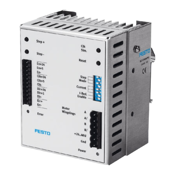
Button 4 Switches 1...8 Plug X2 Plug X3 Fig. 2/3: Front view of the SEC-ST-508 Warning Note the pin assignment on plug connector X3. The unit may become seriously damaged if the connection ter- minals are swapped. Festo SEC-ST-48-6-P01-EN en 0111NH... -
Page 32: Installation
Installation Chapter 3 Festo SEC-ST-48-6-P01-EN en 0111NH... - Page 33 ..........3-11 Measures for complying with EMC guidelines ......3-12 Festo SEC-ST-48-6-P01-EN en 0111NH...
-
Page 34: Material
Test every cable in accordance with the instructions in the section “Fitting the cables.” Make sure that the cables are correctly connected and that the plugs are provided with strain-relief. We recommend the following Festo cables for connection to our electric positioning systems: Cables Designation... -
Page 35: Plug X1 For Control Cable
1 plug connector, 2-pin from Weidmüller, BLZ 5.00/2 SN SW, order no. 162516, included in delivery. 3.1.5 PE connection of the SEC-ST The PE connection of the SEC-ST (mains and motor side) is made via an M4 threaded bolt. Festo SEC-ST-48-6-P01-EN en 0111NH... -
Page 36: Plug Connectors And Their Pin Assignments
Direction input + 24 V (7 mA) Dir +5V Direction input + 5 V (10 mA) Dir- Direction input - Err+ Fault output + (max. 30 mA) Err- Fault output - Fig. 3/2: Assignment of plug connector X1 Festo SEC-ST-48-6-P01-EN en 0111NH... -
Page 37: Motor Cable And Current Supply For The Sec-St
Motor connection winding B end Fig. 3/4: Assignment of plug connector X2 (motor connection) Brief description Meaning/remark + 24...48 V DC Current supply + 24...+48 V DC GND current supply Fig. 3/5: Assignment of plug connector X1 (current supply) Festo SEC-ST-48-6-P01-EN en 0111NH... -
Page 38: Connecting The Cable
Use only screened cables for the connection to the motor and cables twisted in pairs for signal lines. In this way you can avoid electromagnetic interference which might impair reliable operation of the system. Festo SEC-ST-48-6-P01-EN en 0111NH... -
Page 39: Overview Of Connections
In the case of boom arm and multi-axis operation, cables which are subject to mechanical stress must be laid in a drag chain. 3.3.1 Overview of connections Fig. 3/6: Complete structure of SEC-ST with motor and controller Festo SEC-ST-48-6-P01-EN en 0111NH... -
Page 40: Sec-St Complete System
2. Connect the motor cables to the screw terminal of the plug. 3. Connect the PE cable of the motor to the earth terminal PE. 4. If applicable, connect the brake cables to the controller. 5. Check all plug connectors once again. Festo SEC-ST-48-6-P01-EN en 0111NH... -
Page 41: Connecting The Sec-St To The Power Supply
2. Insert plug X1 into the socket on the SEC-ST. 3. Connect the earthing strap of the cable to the earth terminal PE. 4. Insert the 15-pin sub-D plug connector into the stepper motor control card socket. 3-10 Festo SEC-ST-48-6-P01-EN en 0111NH... -
Page 42: Pe Protective Conductor And Screening Connections
In the design of the SEC-ST, great importance has been placed on high resistance to interference. For this reason indi- vidual function blocks are electrically isolated from each other. Signal transmission within the SEC-ST is carried out by an opto coupler. 3-11 Festo SEC-ST-48-6-P01-EN en 0111NH... -
Page 43: Measures For Complying With Emc Guidelines
3. Installation Measures for complying with EMC guidelines If correctly fitted and if Festo cables are used for all the con- nections, the controllers of the SEC-ST product family will comply with the regulations specified in the technical stan- dards EN 50081-2 (interference emission) and EN 61000-6-2 (resistance to interference). - Page 44 Commissioning Chapter 4 Festo SEC-ST-48-6-P01-EN en 0111NH...
-
Page 45: Commissioning The Sec-St
........Festo SEC-ST-48-6-P01-EN en 0111NH... - Page 46 The connected motor may perform a step at this stage. For this reason we recommend that the motor be disconnected from the load in order that a test run can be carried out. Festo SEC-ST-48-6-P01-EN en 0111NH...
-
Page 47: Diagnosis And Error Treatment
When the Step+ button is pressed, the stepper motor turns in a clockwise direction (view of motor shaft of Festo stepper motors type MTR-ST...). It thereby increases its rotational speed step by step. When the Step- button is pressed, the stepper motor turns in the opposite direction. - Page 48 Diagnosis and error treatment Chapter 5 Festo SEC-ST-48-6-P01-EN en 0111NH...
-
Page 49: Fault Messages Of The Sec-St
........Festo SEC-ST-48-6-P01-EN en 0111NH... - Page 50 LED Error lights up red when: – there is excess temperature: The final stage is overheated and is switched off. – there is a short circuit: There is a short circuit between the motor strings or against GND. Festo SEC-ST-48-6-P01-EN en 0111NH...
-
Page 51: Fault Functions Of The Sec-St
– Open brake by applying 24 V DC Motor loses steps Frequency too high – Check characteristic curve of motor, check which torque can be given Motor cannot give torque – Reduce frequency required (controller) Fig. 5/1: Festo SEC-ST-48-6-P01-EN en 0111NH... - Page 52 Technical appendix Appendix A Festo SEC-ST-48-6-P01-EN en 0111NH...
-
Page 53: Technical Appendix
..........Festo SEC-ST-48-6-P01-EN en 0111NH... -
Page 54: Technical Specifications
Type of connection Screw plug terminals Method of fastening TS 35 DIN hat rail Ambient temperature 0 ... + 40 °C (... + 50° at I < 4.7 A) Storage temperature - 25 ... + 60 °C Festo SEC-ST-48-6-P01-EN en 0111NH... -
Page 55: Maximum Ratings
4.8...8 mA 8.4 mA Clk - Dir +24 20...26 V 28 V 5.4...17.2 mA 22 mA Dir +5 4...6 V 7.5 V 4.8...8 mA 8.4 mA Dir - + 24...48 21...50 V 51 V 0...6.5 A Festo SEC-ST-48-6-P01-EN en 0111NH... - Page 56 5...20 mA 30 mA Err- String A 24...48 V 51 V 0...6.5 A String A/ 24...48 V 51 V 0...6.5 A String B 24...48 V 51 V 0...6.5 A String B/ 24...48 V 51 V 0...6.5 A Festo SEC-ST-48-6-P01-EN en 0111NH...
Need help?
Do you have a question about the SEC-ST-48-6-P01 and is the answer not in the manual?
Questions and answers