Table of Contents
Advertisement
Quick Links
Advertisement
Table of Contents

Related Manuals for Festo SEC-ST-48-6-P01


Summary of Contents for Festo SEC-ST-48-6-P01
- Page 1 Motor controller SEC-ST-48-6-P01 Description 8046712 en 1507d [8046714]...
- Page 2 ....... . . [8046714] E Festo AG & Co.KG, D‐73726 Esslingen, Federal Republic of Germany Internet: http://www.festo.com...
-
Page 3: Table Of Contents
..........1-14 Festo SEC-ST-48-6-P01-EN en 1507d English... - Page 4 ........Festo SEC-ST-48-6-P01-EN en 1507d English...
- Page 5 ........Festo SEC-ST-48-6-P01-EN en 1507d English...
-
Page 6: Designated Use
Contents and general instructions Designated use The SEC-ST-48-6-P01, referred to here as the SEC-ST, Smart Electromotor Controller Stepper motor, has been designed for use in control cabinets for controlling stepper motors in 2-string technology. The SEC-ST must be operated in a safe working environment. -
Page 7: Target Group
• Service Please consult your local Festo service centre if you have any technical problems. Notes on the use of this manual This manual will help you in successfully commissioning your SEC-ST for the first time. -
Page 8: General Information On Stepping Motor Systems
Accuracy and resolution The step angle depends on the structural form; for the two- phase Festo stepping motors type MTR-ST, the angle is 1.8° (+/-5%) in full step. A single step takes place when the two coils receive full alternating current. Here, the stepping motor performs a step of 1.8°... - Page 9 The stepping motor’s toler ance must always be taken into account as the absolute value of the full step. This must be considered when very precise positioning as signments are to be executed. Festo SEC-ST-48-6-P01-EN en 1507d English...
- Page 10 Losses of step can occur when decelerating (stopping) just as much as when accelerating! Festo SEC-ST-48-6-P01-EN en 1507d English...
- Page 11 Conversion from full-step to half-step or quarter-step op eration can also provide help. – It is helpful to always operate the motor with its nominal load. If that is not possible, the phase current should be reduced. Festo SEC-ST-48-6-P01-EN en 1507d English...
- Page 12 Also, the motor is warmed even at standstill. If this holding torque is not needed in standstill, it makes sense to reduce the phase current when the motor is at standstill. The Festo stepping motor controller SEC-ST-48-6-P01 offers this option. With these attributes of the stepping motor considered, it provides an economical positioning variant with adequate precision.
-
Page 13: Procedure For Correctly Adjusting The Stepping Motor
In general, it is advantageous to run at half-step to reduce resonance. Current should be reduced when the motor is run without load. Current that is set too high can also cause res onance and thus a loss of step. XIII Festo SEC-ST-48-6-P01-EN en 1507d English... - Page 14 Then the start-stop frequency is reduced again by a good 20% to ensure that no steps are lost during acceleration. A starting value of 400 Hz for small drives and around 200 Hz for large drives can be assumed. Festo SEC-ST-48-6-P01-EN en 1507d English...
- Page 15 The stepping motor is ”pulled” through the critical areas quickly and so does not tend so quickly to oscillate. Increase the friction (emergency solution) • Friction dampens the entire system, but useful torque is lost. Festo SEC-ST-48-6-P01-EN en 1507d English...
-
Page 16: Important User Instructions
This means that failure to observe this instruction may result in damage to property. The following pictogram marks passages in the text which describe activities with electrostatically sensitive compo nents. Electrostatically sensitive components may be damaged if they are not handled correctly. Festo SEC-ST-48-6-P01-EN en 1507d English... - Page 17 Pictograms Information: Recommendations, tips and references to other sources of information. Accessories: Information on necessary or useful accessories for the Festo product. Environment: Information on environment-friendly use of Festo products. Text markings The bullet indicates activities which may be carried out in •...
-
Page 18: Trademarks
The following precautionary measures also apply without claim to completeness: Regulations for setting up high-voltage systems up to • 1000 volts. Electrical equipment for machines. • Equipping high-voltage systems with electronic operat • ing media. XVIII Festo SEC-ST-48-6-P01-EN en 1507d English... -
Page 19: System Summary
System summary Chapter 1 Festo SEC-ST-48-6-P01-EN en 1507d English... - Page 20 ..........1-14 Festo SEC-ST-48-6-P01-EN en 1507d English...
-
Page 21: Overview
1/1, 1/2, 1/4, 1/5, 1/8, 1/10 and 1/32 of a step possible • Step frequency max. 40 kHz • Manual movement with push buttons possible • Protective function against excess temperature and short • circuit Error output • Festo SEC-ST-48-6-P01-EN en 1507d English... -
Page 22: Controller Part
1.4.2 Internal monitoring The end stage possesses an excess temperature cut-out, as well as monitoring in the event of short circuit of the motor strings between each other or against GND. (edition see 1.6. User interfaces) Festo SEC-ST-48-6-P01-EN en 1507d English... -
Page 23: Displays
1. System summary Displays 1.5.1 Ready-to-operate display The blue ready-to-operate LED (Power) on the front of the SEC-ST indicates the readiness to operate. 1.5.2 Fault display A fault is shown by a red LED “Error”. Festo SEC-ST-48-6-P01-EN en 1507d English... -
Page 24: User Interfaces
An incorrect connection may cause damage to the SEC-ST or to the higher-order control. Please note the output levels of your higher-order con • trol. +24 V or +5 V can be used as signal level. Festo SEC-ST-48-6-P01-EN en 1507d English... -
Page 25: Direction Input
An incorrect connection may cause damage to the SEC-ST or to the higher-order control. Please note the output levels of your higher-order con • trol. +24 V or +5 V can be used as signal level. motor step Fig. 1/3: Festo SEC-ST-48-6-P01-EN en 1507d English... -
Page 26: Clock Input
An incorrect connection may cause damage to the SEC-ST or to the higher-order control. Please note the output levels of your higher-order con • trol. +24 V or +5 V can be used as signal level. motor step Fig. 1/5: Festo SEC-ST-48-6-P01-EN en 1507d English... -
Page 27: Fault Output
There is a fault output for logical scanning. SEC-ST-48-6-P01 Fig. 1/6: Caution Note the maximum permitted voltage of + 30 V DC and the maximum permitted current of 30 mA at the fault output Err+. Connecting example Fig. 1/7: Festo SEC-ST-48-6-P01-EN en 1507d English... -
Page 28: Settings
The step mode can be set by the user by means of dip switches 1, 2 and 3. The default value (as at factory) is set as half step. 1/1 step 1/5 step 1/2 step 1/8 step 1/4 step 1/10 step 1/32 step Fig. 1/8: 1-10 Festo SEC-ST-48-6-P01-EN en 1507d English... - Page 29 1. System summary Step designation Number of steps per revolution 1/1 step 1/2 step 1/4 step 1/5 step 1000 1/8 step 1600 1/10 step 2000 1/32 step 6400 1-11 Festo SEC-ST-48-6-P01-EN en 1507d English...
-
Page 30: The Current Setting
5.50 A 6.00 A 3.15 A Fig. 1/9: Caution Observe the maximum permitted holding current of your stepping motor. Please refer to the data sheet of the rel evant motor for the current settings. 1-12 Festo SEC-ST-48-6-P01-EN en 1507d English... -
Page 31: The Current Reduction I-Red
When the motor current is switched on again, the motor wind ings will be energized with the current which was applied immediately before it was switched off. Switch 8 off = motor current off (Default value) Fig. 1/11: 1-13 Festo SEC-ST-48-6-P01-EN en 1507d English... -
Page 32: The Buttons
When the Step+ button is pressed, the stepper motor starts to turn. The direction depends on the wiring of the motor phases; with the stepper motors from Festo: in a clockwise direction (view of motor shaft). It thereby increases its rota... -
Page 33: Fitting
Fitting Chapter 2 Festo SEC-ST-48-6-P01-EN en 1507d English... - Page 34 ........Festo SEC-ST-48-6-P01-EN en 1507d English...
-
Page 35: Dimensions
2. Fitting Dimensions 70.3 Fig. 2/1: Dimensions of the SEC-ST Festo SEC-ST-48-6-P01-EN en 1507d English... - Page 36 The SEC-ST is being cooled by convection. There must be a gap of at least 3 cm on all sides for sufficient cooling. 3 cm Festo SEC-ST-48-6-P01-EN en 1507d English...
-
Page 37: Current Supply
48 V DC is required. The SEC-ST can also be oper ated with 24 V DC. Losses in the dynamics of the stepper mo tors must be taken into account here (see data sheet for the stepper motors). Festo SEC-ST-48-6-P01-EN en 1507d English... -
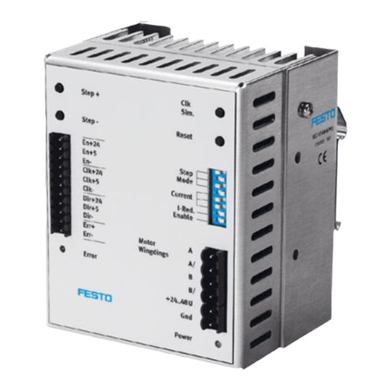
Page 38: Electromechanics: Front View
Plug X2 Plug X3 LED Power Fig. 2/3: Front view of the SEC-ST Warning Note the pin assignment on plug connector X3. The unit may become seriously damaged if the connection ter minals are swapped. Festo SEC-ST-48-6-P01-EN en 1507d English... -
Page 39: Installation
Installation Chapter 3 Festo SEC-ST-48-6-P01-EN en 1507d English... -
Page 40: Material
........3-11 Measures for complying with EMC guidelines ......3-12 Festo SEC-ST-48-6-P01-EN en 1507d English... -
Page 41: Material
– Power supply cable: 10 m – Motor cable: 10 m For cabling the electric components of the system, use only è the cables from the Festo accessories www.festo.com/ catalogue Assemble a cable for connecting the cable screening to the earth terminal of the controller with the following character... -
Page 42: Plug X1 For Control Cable
1 plug connector, 2-pin from Weidmüller, BLZ 5.00/2 SN SW, order no. 162516, included in delivery. 3.1.5 PE connection of the SEC-ST The PE connection of the SEC-ST (mains and motor side) is made via an M4 threaded bolt. Festo SEC-ST-48-6-P01-EN en 1507d English... -
Page 43: Plug Connectors And Their Pin Assignments
Direction input + 24 V (7 mA) Dir +5V Direction input + 5 V (10 mA) Dir– Direction input – Err+ Fault output + (max. 30 mA) Err– Fault output – Fig. 3/2: Assignment of plug connector X1 Festo SEC-ST-48-6-P01-EN en 1507d English... -
Page 44: Motor Cable And Current Supply For The Sec-St
Motor connection winding B end Fig. 3/4: Assignment of plug connector X2 (motor connection) Brief description Meaning/remark + 24...48 V DC Current supply + 24...+48 V DC GND current supply Fig. 3/5: Assignment of plug connector X3 (current supply) Festo SEC-ST-48-6-P01-EN en 1507d English... -
Page 45: Connecting The Cables
Use only screened cables for the connection to the motor and cables twisted in pairs for signal lines. In this way you can avoid electromagnetic interference which might impair reliable operation of the system. Festo SEC-ST-48-6-P01-EN en 1507d English... -
Page 46: Overview Of Connections
In the case of boom arm and multi-axis operation, cables which are subject to mechanical stress must be laid in a drag chain. 3.3.1 Overview of connections Fig. 3/6: Complete structure of SEC-ST with motor and controller Festo SEC-ST-48-6-P01-EN en 1507d English... -
Page 47: Sec-St Complete System
2. Connect the motor cables to the screw terminal of the plug. 3. Connect the cable screening to the earth terminal PE. 4. If applicable, connect the brake cables to the controller. 5. Check all plug connectors once again. Festo SEC-ST-48-6-P01-EN en 1507d English... -
Page 48: Connecting The Sec-St To The Power Supply
2. Insert plug X1 into the socket on the SEC-ST. 3. Connect the cable screening to the earth terminal PE. 4. Insert the 15-pin sub-D plug connector into the stepper motor control card socket. 3-10 Festo SEC-ST-48-6-P01-EN en 1507d English... -
Page 49: Pe Protective Conductor And Screening Connections
In the design of the SEC-ST, great importance has been placed on high resistance to interference. For this reason indi vidual function blocks are electrically isolated from each other. Signal transmission within the SEC-ST is carried out by an opto coupler. 3-11 Festo SEC-ST-48-6-P01-EN en 1507d English... -
Page 50: Measures For Complying With Emc Guidelines
– Power supply cable: 10 m – Motor cable: 10 m If correctly fitted and if Festo cables are used for all the con nections, the devices of the SEC-ST product family will comply with the relevant regulations (see Declaration of Conformity). - Page 51 Commissioning Chapter 4 Festo SEC-ST-48-6-P01-EN en 1507d English...
-
Page 52: Commissioning The Sec-St
........Festo SEC-ST-48-6-P01-EN en 1507d English... - Page 53 The connected motor may perform a step at this stage. For this reason we recommend that the motor be disconnected from the load in order that a test run can be carried out. Festo SEC-ST-48-6-P01-EN en 1507d English...
-
Page 54: Diagnosis And Error Treatment
When the Step+ button is pressed, the stepper motor starts to turn. The direction depends on the wiring of the motor phases; with the stepper motors from Festo: in a clockwise direction (view of motor shaft). It thereby increases its rota... - Page 55 Diagnosis and error treatment Chapter 5 Festo SEC-ST-48-6-P01-EN en 1507d English...
-
Page 56: Fault Messages Of The Sec-St
........Festo SEC-ST-48-6-P01-EN en 1507d English... - Page 57 LED Error lights up red when: – there is excess temperature: The final stage is overheated and is switched off. – there is a short circuit: There is a short circuit between the motor strings or against GND. Festo SEC-ST-48-6-P01-EN en 1507d English...
-
Page 58: Fault Functions Of The Sec-St
– Open brake by applying 24 V DC Motor loses steps Frequency too high – Check characteristic curve of motor, check which torque can be given Motor cannot give torque – Reduce frequency required (controller) Fig. 5/1: Festo SEC-ST-48-6-P01-EN en 1507d English... - Page 59 Technical appendix Appendix A Festo SEC-ST-48-6-P01-EN en 1507d English...
-
Page 60: A. Technical Appendix
........Festo SEC-ST-48-6-P01-EN en 1507d English... - Page 61 0 ... + 40 °C (... + 50° at I < 4.7 A) Storage temperature –10 ... +60 °C Relative humidity 95 % (non condensing) Protect from humidity, no moisture condensation Protection class IP20 Certification CE symbol Fig. A/1: Festo SEC-ST-48-6-P01-EN en 1507d English...
-
Page 62: A.1.2 Maximum Ratings
30 mA Err- String A 24...48 V 51 V 0...6.5 A String A/ 24...48 V 51 V 0...6.5 A String B 24...48 V 51 V 0...6.5 A String B/ 24...48 V 51 V 0...6.5 A Festo SEC-ST-48-6-P01-EN en 1507d English...
Need help?
Do you have a question about the SEC-ST-48-6-P01 and is the answer not in the manual?
Questions and answers