Table of Contents
Advertisement
Quick Links
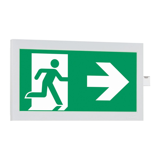
CEAG GuideLed Einzelbatterieleuchten CGLine+
CEAG GuideLed self contained luminaires CGLine+
Montage- und Betriebsanleitung
Mounting and Operating Instructions
Zielgruppe: Elektrofachkraft
Target group: Skilled electricians
Verwendungszweck: Notbeleuchtung, nicht für privaten Gebrauch
Intended Application: Emergency Lighting, not suitable for private use
Advertisement
Table of Contents


Need help?
Do you have a question about the CEAG GuideLed CGLine+ Series and is the answer not in the manual?
Questions and answers