Table of Contents
Advertisement
Advertisement
Table of Contents

Subscribe to Our Youtube Channel
Related Manuals for Trotec 8016 Speedy 100 fiber


Summary of Contents for Trotec 8016 Speedy 100 fiber
- Page 1 OPERATION MANUAL 8016 Trotec Speedy 100 fiber...
- Page 2 Trotec cannot be held responsible for any direct or indirect damages, which result from using or working with the products electric circuits or software described herein. The apparatus must be used only by trained and skilled personnel. Before use the manual should be read and followed carefully.
-
Page 3: Table Of Contents
TABLE OF CONTENTS 1 GENERAL ......................5 1.1 Operation Manual Use – General Information ............5 1.2 Designated Use ......................6 1.3 Disposal remarks ...................... 6 1.4 Technical Data / System Specification ..............7 1.5 Manufacturer's Label ....................8 1.6 EU – Declaration of conformity ................9 2 SAFETY ........................10 2.1 General Safety Information .................. - Page 4 6.5 Response Form ....................... 52 6.6 How to create a Service File ................... 53 BA 8016_2.0_EN(10/2016) 4 / 55...
-
Page 5: General
GENERAL 1.1 Operation Manual Use – General Information Caution: Please read and follow the instruction in this Operation Manual carefully, before installation and operation. Damage to persons and/or material can result from not following individual points of the Operation Manual! Operation of the system is only permitted with equipment and spare parts supplied or listed in the spare parts and consumables lists. -
Page 6: Designated Use
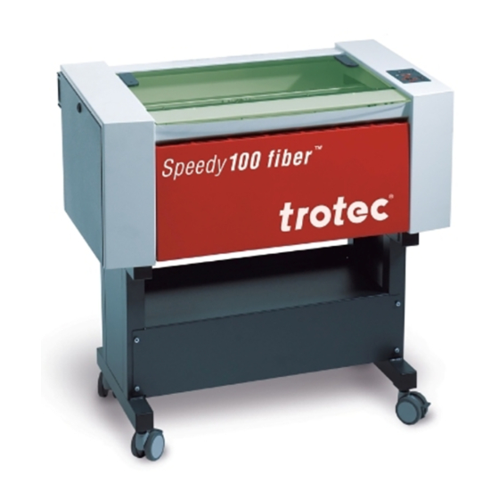
1.2 Designated Use The Trotec Speedy 100 fiber is used for marking on metals and plastics. Many metals and most plastics will show interaction with the laser beam. However, very clean metallic surfaces which are highly polished and pure could show NO reaction. This is due to too high reflectivity at 1064nm wavelength which is given especially for silver and copper. -
Page 7: Technical Data / System Specification
1.4 Technical Data / System Specification Mechanic Working area 24 x 12 inch / 610 x 305 mm Max. height of workpiece 4.9 inch / 125 mm with 3.2 inch lens Max. engraving speed 78 inch/sec / 200 cm/sec Motor Brushless DC Servo motor Encoder Increment... -
Page 8: Manufacturer's Label
1.5 Manufacturer's Label The manufacturer's label is located on the back of the machine (see Figure below). It is recommended to enter data such as serial number and year of manufacture into the manufacturer's label below so that you always have this data at hand if necessary, BA 8016_2.0_EN(10/2016) 8 / 55... -
Page 9: Eu - Declaration Of Conformity
Linzer Strasse 156, A-4600 Wels, OÖ., AUSTRIA hereby declares that the following product Trotec 8016 Speedy 100 fiber Model N° 8016 Speedy 100 fiber has demonstrated conformity to the following guidelines: 2006/42/EG Directive for Machines 2006/95/EG Low Voltage Directive 2004/108/EG EMC Guideline... -
Page 10: Safety
SAFETY Please read this chapter before operating or servicing a Trotec Speedy 100 fiber laser system! 2.1 General Safety Information All personnel involved in installation, set-up, operation maintenance and repair of the machine, must have read and understood the Operation Manual and in particular the "SAFETY" section. The user is... - Page 11 Safety Information for the User and/or Operating Personnel No work methods are permitted that affect the safety of the machine. The operator must also ensure that no unauthorized persons work with the machine (e.g. by activating equipment without authorization). ...
-
Page 12: Laser Safety Information
To assess the potential dangers laser systems pose, they are classified into 5 safety classes: 1, 2, 3a, 3b and 4. Trotec Speedy 100 fiber is a machine of class 2 (USA: Class II). This is guaranteed by the protective housing and the safety installations. - Page 13 Dangerous radiation exposure can result from the use of materials other than described in Section 1.2 Designated Use: In case of using highly reflecting materials like blank or polished metals metals with very high reflectivity like copper, brass, gold, silver ...
-
Page 14: Safety Precautions When Operating The Machine
2.3 Safety Precautions when Operating the Machine In your Trotec Speedy 100 fiber, a closed safety system is integrated which immediately switches off the power to the laser tube when the protection cover is opened. Consequently an incomplete marking can occur if the cover is opened during operation. Therefore, first press the "PAUSE"... -
Page 15: Warning And Information Labels
2.4 Warning and Information Labels The warning and information labels are attached in such positions of the machine that could represent a source of danger during set-up and operation. Therefore, follow the information on the labels. If labels are lost or damaged, they must be replaced immediately. - Page 16 BA 8016_2.0_EN(10/2016) 16 / 55...
-
Page 17: Before Operation
BEFORE OPERATION 3.1 Unpacking You receive your Trotec laser machine packed in a cardboard box or wooden box, which contains the laser and additional accessories. The following steps give you an overview of the unpacking and assembly of the laser. Please follow these steps carefully. -
Page 18: Contents Of Delivery
Transport and service packaging Laser inclusive optics Stand (optional) Accessories box, containing: 1. CD Trotec software / printer driver incl. Operation Manual 2. Mains cable 3. Computer connection cable USB 4. Computer connection cable serial (optional) 5. -
Page 19: Location
3.3 Location Before you install the laser system, you should select an appropriate location. Follow the guidelines shown below: Avoid locations where the system is exposed to high temperatures, dust and high humidity. (The humidity must not exceed 70% and the temperature must not be close to the dew point.) Avoid locations, where the system is exposed to mechanical shocks. -
Page 20: Exhaust System - Requirements
3.4 Exhaust System – Requirements Do not start the machine without an adequate exhaust system. 3.5 Computer – Requirements The following recommendation represents the minimum requirements. When using a more powerful computer the graphics are generated and displayed faster and the computing times and the data transfer to the laser are reduced. -
Page 21: Connections
3.6 Connections Perform the connections exactly in the order described, otherwise electrostatic charging can damage your computer and/or die electronics of the laser system. 3.6.1 Connecting the Mains Connect one end of the mains cable with the connection socket at the rear side of the laser machine (1) and the other end with a protected power outlet. -
Page 22: Connecting The Computer
3.6.2 Connecting the Computer The computer must be switched off and connected to the mains voltage. Connect the laser to a free serial (1) or USB (2) interface on your computer using the cable from the accessories box. BA 8016_2.0_EN(10/2016) 22 / 55... -
Page 23: Connecting The Exhaust System
Plug the ends of the exhaust duct into the allocated connection (2). The position of the connector depends on the type of exhaust system. When using the Trotec exhaust system, also connect it with the cable included to the remote control connector of the laser (3). -
Page 24: Operation
OPERATION 4.1 Machine view and connections 1 Top lid 11 Exhaust hose connector 2 Autofocus sensor 12 Manufacturers label 3 Service access panel 13 Laser module (Rack) 4 Connection Socket for Rotary 14 Laser collimator cover 5 Focusing head 15 Power supply 6 X-axis 16 Power socket and fuses 7 Ruler... - Page 25 10 Maintenance panel BA 8016_2.0_EN(10/2016) 25 / 55...
- Page 26 Top lid If the Top lid is opened, no data is processed. After closing the Top lid, the device is not ready to process commands for 5 seconds. If the protection cover is opened during operation, the motion system is stopped and laser source is turned off.
- Page 27 Used to align material and measure it. BA 8016_2.0_EN(10/2016) 27 / 55...
- Page 28 Working Table The work pieces to be processed are put onto the working table. To facilitate orientation, a horizontal and a vertical ruler are located on the working table. The table is ferromagnetic for easier fixation of work pieces. Keypad The Keypad contains multiple buttons and displays for controlling the device.
- Page 29 PC connection cable (USB) BA 8016_2.0_EN(10/2016) 29 / 55...
-
Page 30: Power Switch (On / Off)
4.2 Power switch (ON / OFF) Switches the mains supply ON/OFF. Before switching on the machine, the user must make sure that no objects of any kind are located inside the operating space, which could limit or obstruct the mechanics of the machine. The following conditions must be fulfilled for correct start up: - unrestricted freedom of motion of the mechanics - protection cover closed... -
Page 31: Keypad
4.3 Keypad POSITIONING KEYS Z When pressing one of these two keys the engraving table moves in Z direction (upwards or downwards). Use these positioning keys to move the work piece manually. When both keys are pressed simultaneously, the material is focused automatically (only with light barriers = option). - Page 32 By pressing the “Shift” key and a Z- positioning key an automatic move to the corresponding end- positions is performed: Shift + Down: the table moves down to the lowest possible position Shift + Up: the table moves up to the autofocus- position. Note: Shift + Up will cause the head moving backwards to the light barriers (according simultaneous pressing of both z-keys).
- Page 33 START (REPEAT) By pressing “Start (Repeat)”, the jobs which are currently positioned on the selected plate in the Trotec JobControl are started. If the jobs have been processed before, they will be reset automatically. STATUS INDICATOR LASER BEAM Indicates, that a laser beam is currently being emitted.
- Page 34 STATUS DISPLAY Indicates the current status of the device: green, flashing slowly (0.5 Hz) Machine is ready green, flashing fast (2 Hz) Cover has been opened green permanent light / Data available in the machine Pause mode red permanent light Laser beam is being emitted Cover open during switch-on process, green/red flashing alternately...
-
Page 35: First Steps Before Marking
4.4 First Steps before Marking To prepare your laser marker for the first marking tests, perform the following steps: Switch the machine on with the ON / OFF switch. The working table automatically references in X/Y/Z direction. Open the protection cover and place work piece on the working table. Usually you position the work piece into the upper left-hand corner of the marking table against the horizontal and vertical rulers. - Page 36 There are three methods to focus the laser beam: Manual focusing Focusing by software Automatic focusing by means of light barriers (optional) To A – Manual focusing: Move the processing head over the material to be engraved by means of the positioning keys X/Y Hang the focus tool on the external ring of the working head so that the focus tool can move unhindered.
- Page 37 To B – Focusing by software: Click the icon “focus laser” in the Trotec JobControl The working table moves in Z direction. The following values are used to determine the focus position and therefore always have to be checked before using this focus option:...
-
Page 38: Lateral Air Assist
When the air assist nozzle is installed, the optical autofocus does not work. 4.4.1 Lateral Air Assist During laser engraving and laser cutting, the supply of compressed air can significantly influence and improve results. Air assist is often used with vector cutting applications to derive heat and flammable gases from the cutting surface. -
Page 39: First Marking Tests
4.5 First Marking Tests The following steps describe how to successfully mark a first pattern. Please follow the individual steps: First switch on the computer, then the laser machine. Put the object to be marked into the laser and move into the desired position on the table. - Page 40 Also consult the Software Manual for further information. Select "File Print", to access the Trotec printer driver, where you can perform work piece and material settings as well as specify a job name or a job number. This file is automatically transferred into the Trotec JobControl.
-
Page 41: Maintenance
MAINTENANCE 5.1 Cleaning the System Caution – use of controls or adjustments or performance of procedures other than those specified herein may result in hazardous laser radiation exposure. Before starting cleaning and maintenance work always switch off the machine and unplug the mains plug. You should check at least once a day, whether dust has accumulated in the marking system. -
Page 42: Cleaning The Optical Parts
5.2 Cleaning the Optical Parts Trotec recommends to use following cleaning material: Lens tissues Part number 69249 Lens cleaner Part number 69248 The lens has a durable multi-coating and won’t be damaged by correct and careful cleaning. You should inspect the mirrors and the lens according the maintenance plan. If you discover a veil of haze or dirt, you must clean them. - Page 43 8. Hold the lens assembly by its edge with a lens cleaning tissue and use a drop of lens cleaning liquid from the little bottle which you received as an accessory delivered with the laser. While holding the lens on an angle, flush both surfaces of the lens, to wash away coarse soiling.
-
Page 44: Cleaning The Mirrors
5.2.2 CLEANING THE MIRRORS There are two mirrors in the operating area of the laser, which may have to be cleaned if they are soiled. To clean the mirrors, follow the instructions below. MIRROR #2 1. The mirror # 2 is located on the right-hand side of the machine. To be able to access mirror #2, you must remove the right maintenance panel by using the delivered Allen key. - Page 45 MIRROR #3 Mirror #3 is situated on the working head. 1. While holding the mirror, loosen the big screw (1) and lift the mirror from the laser head. Pay attention that the mirror doesn't grind over the mirror holder, as it can be scratched very easily.
-
Page 46: Maintenance Plan
5.3 Maintenance Plan daily weekly monthly yearly Laser Lens, mirror 3 Check Cleaning if required Mirror 2 Check Cleaning if required Marking table and rulers Cleaning Cover of the laser tube Cleaning and housing Entire working area – Cleaning general cleaning Exhaust System Bag filter Filter mat... -
Page 47: Additional Information
ADDITIONAL INFORMATION Material Table Legend: Quality: Process. Perfect + + + Annealing Working well Engraving No good quality Color Change Quite bad not applicable Not reacting Back reflection (in rare cases) Speedy 100 fiber Quality Process Metals: Aluminum: Aluminum anodized: Brass: Brass polished: Chromate:... - Page 48 Caution when processing conductive materials (carbon fibers,…)! Conductive dust or particles in the ambient air might damage electrical components and lead to short circuits. Bear in mind that those defects are NOT warranted. BA 8016_2.0_EN(10/2016) 48 / 55...
-
Page 49: Tips For Troubleshooting
Check whether the sorting function "Kind" and "Resolution" are activated in the waiting list. Make sure that the directory ”Spool” has been created in the directory of JobControl (”Trotec”) and that the correct path to this directory has been set under "Options" in the "Settings" menu. ... -
Page 50: Acceptance Report
6.3 Acceptance report Dear customer! Please check applicable items: Machine parts checked for shipping damage We request your confirmation of Machine parts checked against delivery note properly completed transfer of Setup of the machine discussed the machine ... -
Page 51: Training Schedule
6.4 TRAINING SCHEDULE Employee/Trainee: Trainer: Date of Training: The above mentioned Employee received instruction on the operation of the Speedy 100 fiber Lasersystem. Especially the following topics are covered: - Machine Function - Danger Area - Warnings - Interlock System - Taking into Service and Shutdown - Work Flow - Announcement of unexpected working result and the resulting procedure... - Page 52 6.5 Response Form If you face any trouble with the machine, please provide the following information and add a Servicefile (procedure is described on the following pages). Date Machine Details Contact Details Serialnumber Name JobControl Version Country Driver Version Phone Number Layout Software Email address Firmware Version...
- Page 53 6.6 How to create a Service File 1. Start JobControl and go to Settings> Create Service File. 2. The window „Save Service File to“ shows up. Please select a directory to save the file and click on „Save“. BA 8016_2.0_EN(10/2016) 53 / 55...
- Page 54 3. The window „Add Layout File“ shows up. Please select the layout file, which was sent most recently to JobControl and possibly caused a failure (example: Corel file, Photoshop file, AutoCAD file,…). Click on „Open“. 4. The following window confirms, that the Service File (ServiceLog.txt) was created successfully.
- Page 55 BA 8016_2.0_EN(10/2016) 55 / 55...
Need help?
Do you have a question about the 8016 Speedy 100 fiber and is the answer not in the manual?
Questions and answers