Table of Contents
Advertisement
Quick Links
Advertisement
Table of Contents

Related Manuals for Trotec Rayjet U300 fiber


Summary of Contents for Trotec Rayjet U300 fiber
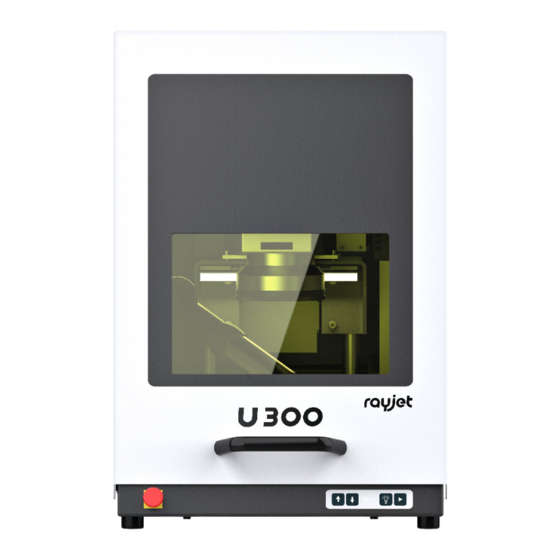
- Page 1 U300 fiber Operating manual 8040 OM 8040_1.6_EN (10/2022) ENGLISH (Translation)
- Page 2 Trotec Laser GmbH Trotec Laser Pty Ltd Trotec Laser België Trotec Laser Belgique +43 7242 239-7070 +61 26413-5904 +31 850 70 51 55 service-at@troteclaser.com service@troteclaser.com.au support@troteclaser.nl Trotec Laser Canada Trotec Laser AG Trotec Laser GmbH +1 800 663 1149-902 +41 32387-1611 +86 189 500 735 62 techsupport@troteclaser.ca...
- Page 3 Trotec Laser GmbH Freilingerstraße 99 4614 Marchtrenk, Austria General contact to Technical Support: Tel.: +43 7242 239-7000 E-mail: techsupport@troteclaser.com www.troteclaser.com ENGLISH (Translation) ENGLISH (Translation) 3 / 59...
- Page 4 Technical Changes Technical specifications are subject to change without notice. Trotec Laser GmbH reserves the right to improve or modify any of the products without prior notice. © Copyright This documentation with all illustrations is intellectual property of Trotec Laser GmbH.
-
Page 5: Table Of Contents
Content Introduction............................8 General Information..........................9 Information about this manual....................9 2.1.1 Information about this manual....................9 2.1.2 General instructions for using the manual................9 Explanation of symbols......................10 Liability and warranty......................11 Scope of delivery (standard configuration)................12 Type plate..........................12 Safety..............................14 General safety notes....................... - Page 6 Storage conditions........................27 Place of storage........................28 Transport inspection and reporting of defects................ 28 Setup and installation......................... 29 For your safety........................29 Temperature and humidity.......................29 Installation location........................29 Mechanical installation......................30 Electrical installation........................ 31 6.5.1 Overview marking head interface (back side)..............31 6.5.2 Overview laser rack interface (back side)................
- Page 7 Contact details............................. 50 Disassembly............................51 Disposal..............................52 Appendix...............................53 15.1 Datasheet 8040 U300......................54 15.2 CE 8040 U300........................59 ENGLISH (Translation) ENGLISH (Translation) 7 / 59...
-
Page 8: Introduction
Introduction The U300 fiber is a second generation of a high quality marking laser. The Yb fiber laser source means the system has an extremely long life cycle and minimal maintenance costs. This system is maintenance free apart from the filter pad and processing lens. The combination of a high quality galvanometer scanner and a fiber laser produce highly precise marking results in short marking times. -
Page 9: General Information
General Information For the sake of readability, gender-neutral endings are not used in this operation manual. It is hereby expressly stated that all parts of the text where natural persons or groups of persons are mentioned refer to people of all genders. Information about this manual 2.1.1 Information about this manual Before beginning any work on the machine, read this manual completely and carefully. -
Page 10: Explanation Of Symbols
The U-Series includes Class 4 laser marking systems according to IEC 60825-1 "safety of laser products". If the U50 or U300 is integrated as an OEM component, the operator bears sole responsibility for compliance with the legal standards and safety guidelines. The operator of the laser marking system is obliged to comply with the "applicable safety regulations"... -
Page 11: Liability And Warranty
Nonobservance of the operation, maintenance and service instructions described within this manual absolves Trotec Laser GmbH from any liability in case of a defect. Furthermore, Trotec Laser GmbH shall accept no liability whatsoever for damage caused by the use of non- original parts and accessories. -
Page 12: Scope Of Delivery (Standard Configuration)
Scope of delivery (standard configuration) – Power cord – Software and manuals on storage medium – Lens cleaning tissues – Allen key set – Key for Rack – Key for PC (optional) – Plug X11, X31, X71 – PC Recovery USB-Stick (optional) –... - Page 13 Enter the serial number, model and year of construction of the machine here. This data is important should the unit experience a fault and for ordering replacement parts. Serial number: Model: Year of manufacture: ENGLISH (Translation) ENGLISH (Translation) 13 / 59...
-
Page 14: Safety
Safety TO AVOID POSSIBLE HARM READ AND FOLLOW THESE INSTRUCTIONS. The machine is built at the time of it's development and production according to applicable, established technical rules and is considered to be safe to operate. Dangers can be caused by the machine if the machine: is operated by unqualified personnel, •... - Page 15 Warning Risk posed by incorrect operation by unauthorized individuals. Setting and operating the machine with limited knowledge of its function can lead to injury and/ or damage to the machine. – Never leave the machine unattended while in operation. – Turn off the machine at the main switch when not in use.
-
Page 16: Intended Use
The machine may only be operated by suitably trained individuals. – Observe effective safety regulations and the procedures described in this operating manual. If the intention is to use the system for other applications, Trotec Laser GmbH should be informed in advance. 3.1.2 Improper use Use of the machine for any purposes other than those intended or described in the present manual is regarded as improper and therefore prohibited. -
Page 17: Machine Modification
The service operation is therefore declared as laser class 2 (US: class II) and proper precautions need to be taken (see "Laser classification"). 3.1.6 Applicable safety regulations The following directives and guidelines must be observed to avoid hazards when operating Trotec laser systems: ENGLISH (Translation) - Page 18 Therefore, always observe the directives as well as the regulations of the institutions for statutory accident insurance association applicable to you. The operator is responsible for fulfilling all safety requirements, as Trotec Laser GmbH has no influence on the proper use of the machine.
-
Page 19: Laser Safety
Laser safety 3.2.1 Laser classification The laser safety class indicates the risk potential based on the level of accessible laser radiation. The U300 fiber is a laser class 2 product and complies to the latest safety norms and regulations (IEC 60825-1). -
Page 20: Areas Of Responsibility
Areas of responsibility 3.3.1 Responsibilities of the operating company The operator has the following responsibilities: It is the responsibility of the operator to comply with the national official and statutory regulations for the • operation of a class 2 (US: class II) laser system or laser system with a build in laser source of class 2 (US: class II). -
Page 21: Requirements For Operating An Service Personnel
The machine and its components, such as the lens and mirrors, are to be kept clean at all times. • Caution The adjustment of the beam path may only be carried out by service personnel of Trotec Laser GmbH. Requirements for operating an service personnel The requirements for the operating and service personnel are: The personnel must have read and understood this manual and in particular the "Safety"... - Page 22 If any warning and safety stickers are lost or damaged, the user is not able identify risks anymore, and there is danger of injury. – Replace lost or damaged labels immediately. – Contact your Trotec Laser GmbH dealer for details. ENGLISH (Translation) ENGLISH (Translation) 22 / 59...
-
Page 23: Secondary (Indirect) Hazards
Secondary (indirect) hazards 3.6.1 Fire hazard Warning Fire hazard Fire hazard from gas and processing of inflammable materials. – Do not operate the device without supervision. – Keep CO fire extinguisher ready at hand in the immediate vicinity of the device. ENGLISH (Translation) ENGLISH (Translation) 23 / 59... -
Page 24: Gases, Fumes And Dust
• Notice After a deletion, Trotec Technical Support must be involved before the system is put back into operation. What to do in the event of an accident, first aid If eye damage occurs due to laser radiation, the casualty must present to an ophthalmologist •... - Page 25 – Remove the key switch. – Unplug the power cable. Rescue the injured person from the danger area and provide first aid. • Call an emergency doctor! • ENGLISH (Translation) ENGLISH (Translation) 25 / 59...
-
Page 26: Before Commissioning
Record all details in writing immediately. • Note all claims on the transportation documents. • Photograph any damage. • Send report to Trotec Laser GmbH. • Nach dem Entladen: Remove all transport packaging. • Check the delivery for completeness. •... -
Page 27: Transport And Storage
Transport and Storage Transport conditions When transporting outside, always transport in a covered vehicle or one with sufficient weather-proofing. • Protect the machine against transportation damage using straps and inserts, and leave sufficient • distance between other transported items. Ambient temperature for transportation: •... -
Page 28: Place Of Storage
Place of storage Storage room or boxed with sufficient weatherproofing. The storage location must be free from corrosive elements, fumes and flammable materials. Transport inspection and reporting of defects Immediately after receipt inspect the delivery to ensure that it is complete and has not suffered any •... -
Page 29: Setup And Installation
Setup and installation For your safety Notice The setup has to be carried out by Technical Support. Temperature and humidity Ambiente conditions +15 °C to +35 °C (59 °F to 95 °F) Operating temperature (ambiente temperature): max. 60%, non-condensing Relative humidity: If the system has been exposed to large temperature fluctuations, it must first be brought back to room •... -
Page 30: Mechanical Installation
Mechanical installation The correct, stable and reproducible alignment of the working head in relation to the workpiece to be marked is a prerequisite for faultless marking results. The marking head should therefore be installed with appropriate care. Alignment The focal plane lies parallel to the working head base plate. When installing the marking head it is therefore important to ensure that the marking head base plate is aligned as parallel as possible to the intended processing plane. -
Page 31: Electrical Installation
Electrical installation Following the mechanical installation of the marking head, laser rack and PC, the components must be connected to one another electrically. (The laser rack and marking head are already connected to one another on delivery.) The peripherals (power supply, external control and safety signals, etc.) are then connected via the laser rack and PC interfaces. -
Page 32: Overview Laser Rack Interface (Back Side)
6.5.2 Overview laser rack interface (back side) Notice Before the laser marker can be put into operation, the external safety circuits and the external start and stop signals must be connected. Caution When making these connections, the operator must ensure that all safety circuits comply with the respective valid national standards and guidelines for the use of laser devices. - Page 33 X61 – Exhaust system This connector is used to control, start and stop a Trotec extraction unit. Only use the original cable supplied. X71 – Start / Stop The X71 connector may be used to send start and stop signals via an external controller or receive a signal from the laser.
-
Page 34: Overview Pc Interface (Back Side)
Warning The maximum load of each of the digital 24V outputs on the interface is 100mA. A short circuit of the outputs must be avoided as it will damage the respective inputs. 6.5.3 Overview PC interface (back side) The machine is connected to the Ethernet via a cable connection from the LAN interface on the rear of the PC rack to the LAN interface on the laser rack. -
Page 35: Interface Pin Configuration
6.5.5 Interface pin configuration X11 – Safety circuit (Emergency stop button / interlock safety switch / external messages) X31 - External panel X71 – Start / Stopp ENGLISH (Translation) ENGLISH (Translation) 35 / 59... - Page 36 I/O Input/Output ENGLISH (Translation) ENGLISH (Translation) 36 / 59...
-
Page 37: Machine Overview
Machine overview Front view 1 Safety door incl. safety glass 5 z-axis 2 Safety door handle 6 Marking head 3 Keypad 7 Exhaust 4 Emergency stop button 8 T-slot table Back view 1 Backside of marking head 2 Type plate 3 Laser safety protection elements 4 Exhaust connector 5 Cable opening... -
Page 38: Operation
Operation Installation inspection The following points must be checked to ensure correct installation: Correct power supply connections and fuses. • Complete and correct mechanical and electrical installation. • Check that the mechanical and electrical installation is complete and correct Input voltages. •... -
Page 39: Power On/Off
Power On/Off 1. Press the main switch (1) on the laser rack. → The shutter is closed. The main switch and the two status lamps on the marking head illuminate in yellow. 2. Put the key in the key switch (7) (vertically) and turn 90° to the right. 3. -
Page 40: Control Panel Laser Rack
Control panel laser rack Laser rack Number Description Types Main switch toggle switch System ready control lamp Shutter control lamp Laser busy control lamp Emergency stop button switch Error reset button Key switch switch Keypad control 1 z-axis: Up-button 2 z-axis: Down-button 3 Status indicator laser beam LED on: The machine is processing data. - Page 41 This is indicated by a separate display on the marking head and/or by a luminous control lamp (shutter) on the laser rack. Meaning of the signal colors Emission indicator off - Device de-energised. Emission indicator status yellow - shutter is closed, no laser power output.
-
Page 42: Focusing
Focusing Notice It is absolutely essential to maintain the correct focal distance for every laser marking process. Only when in focus will the laser beam achieve the power density necessary for permanent and clearly legible marking. Prior to any marking it is therefore necessary to set the correct focal distance between the marking head and the workpiece. -
Page 43: Ingetration / Connection
Ingetration / Connection Switching sequences Switching sequence diagrams are provided for various standard processes which indicate the interplay of the individual signals. ENGLISH (Translation) ENGLISH (Translation) 43 / 59... - Page 44 ENGLISH (Translation) ENGLISH (Translation) 44 / 59...
-
Page 45: Maintenance
Maintenance 10.1 Safety notes Caution Before any maintenance work takes place, ensure that the power supply has been switched off and the system is de-energised. Notice All maintenance work must be carried out according to the safety regulations. In order to ensure the maximum availability and lifetime of the system, we recommend you regularly check the filter system and ventilation and keep the surrounding area clean. -
Page 46: Cleaning The Optics
10.3 Cleaning the optics This system is fitted with high quality optical components, which under normal operating conditions are maintenance free for their lifetime. However, it may be necessary to clean output lenses, e.g. the scanner flat field lens (f-theta objective) if it becomes covered in dust or fumes. Notice Never touch the optical components with your fingers! Oily or dirty hands may damage the lens surfaces. -
Page 47: Troubleshooting
This chapter should assist maintenance personnel with the identification and resolution of operational faults based on error messages and symptoms. Danger Maintenance and repair work should only be carried out by Trotec Laser GmbH or one of its authorized personnel under observation of the safety regulations. 11.1 Error, cause and remedy... -
Page 48: Possible Error Messages
Warning System errors which cannot be reset or which indicate a hardware error should only be resolved by Trotec Laser GmbH trained service personnel. Error message Cause Card off line. - Page 49 Error message Cause 24V monitoring. Shutter temperature. Required shutter position. ENGLISH (Translation) ENGLISH (Translation) 49 / 59...
-
Page 50: Contact Details
Contact details Technical Support In case of questions, contact our experienced Technical Support in your local area. For global service contact numbers and further information please see our website, section "Support": www.troteclaser.com When calling, please make sure that the machine is in your immediate vicinity, and that you have the following information ready (see response form): At which working process did the problem occur? What you have done so far to correct the problem. -
Page 51: Disassembly
Disassembly Warning Danger of injury when disassembling the machine. There is danger of injury when disassembling the machine. Always wear suitable protective clothing (e.g. safety goggles, safety shoes, safety gloves). Warning Dangerous electrical voltage Electric current. The machine must be disconnected from the main power supply. Notice –... -
Page 52: Disposal
Disposal Disposal Do not dispose of the machine with domestic waste! Electronic devices have to be disposed of according to the regional directives on electronic and electric waste disposal. In case of further questions, please ask your supplier. In case of disassembly, use suitable tools to dismantle the unit into individual parts. Sort the individual parts and have them disposed of professionally. -
Page 53: Appendix
Appendix ✓ Technical Data ✓ Conformity Declaration Acceptance report Response form Training verification form ENGLISH (Translation) ENGLISH (Translation) 53 / 59... -
Page 54: Datasheet 8040 U300
Technical Datasheet U300 www.rayjetlaser.com Subject to change without notice. Errors and omissions excepted. V004... - Page 55 Technical Datasheet www.rayjetlaser.com Subject to change without notice. Errors and omissions excepted. V004...
- Page 56 Technical Datasheet U300 – Marking Head and Lens Configuration www.rayjetlaser.com Subject to change without notice. Errors and omissions excepted. V004...
- Page 57 Technical Datasheet U300 - Dimensions www.rayjetlaser.com Subject to change without notice. Errors and omissions excepted. V004...
- Page 58 Technical Datasheet Laser Rack www.rayjetlaser.com Subject to change without notice. Errors and omissions excepted. V004...
Need help?
Do you have a question about the Rayjet U300 fiber and is the answer not in the manual?
Questions and answers