Dahua VTH5221 Series Quick Start Manual
Digital vth
Hide thumbs
Also See for VTH5221 Series:
- User manual (109 pages) ,
- User manual (105 pages) ,
- User manual (93 pages)
Table of Contents
Advertisement
Advertisement
Table of Contents

Related Manuals for Dahua VTH5221 Series


Summary of Contents for Dahua VTH5221 Series
- Page 1 Digital VTH (Version 4.3) Quick Start Guide V1.0.1...
-
Page 2: Foreword
Foreword General This document mainly introduces structure, installation process, debugging and verification process of digital VTH products. Device Upgrade Please don’t cut off power supply during device upgrade. Power supply can be cut off only after the device has completed upgrade and has rebooted. Safety Instructions The following categorized signal words with defined meaning might appear in the Manual. - Page 3 The Guide would be updated according to the latest laws and regulations of related regions. For detailed information, see the paper User's Manual, CD-ROM, QR code or our official website. If there is inconsistency between paper User's Manual and the electronic version, the electronic version shall prevail.
-
Page 4: Important Safeguards And Warnings
Important Safeguards and Warnings The following description is the correct application method of the device. Please read the Guide carefully before use, in order to prevent danger and property loss. Strictly conform to the Guide during application and keep it properly after reading. Operating Requirement Please don’t place and install the device in an area exposed to direct sunlight or near heat ... -
Page 5: Table Of Contents
1 Product Structure ..........................1 Front Panel ............................ 1 Rear Panel Port..........................2 1.2.1 VTH5221 Series/VTH5241 Series ..................2 1.2.2 VTH5221E-H/VTH5221EW-H .................... 2 1.2.3 VTH15XX-S2 Series Type B/Type CH & VTH15XX Series Type B/Type CH ....2 1.2.4 VTH5222CH/VTH5222CHW-2 ................... 4 1.2.5 VTH1660CH ........................ -
Page 6: Product Structure
Product Structure Front Panel Different models of devices may have different front panel dimensions and key types, but keys or indicators with the same silkscreen or icon have the same function. Please refer to Table 1-1 for details. Table 1-1 Front panel description Icon Name Description... -
Page 7: Rear Panel Port
Rear Panel Port 1.2.1 VTH5221 Series/VTH5241 Series VTH5221 series and VTH5241 series have different port positions at the rear panel, but the same port provides the same function. Taking VTH5221 as an example, specific functions of ports are introduced, as shown in Figure 1-1. - Page 8 Figure 1-3 VTH15XX-S2 type CH series In VTH15XX-S2 type B series, different types of digital VTH have different port positions, but the same port provides the same function. Taking VTH1560B-S2 as an example, specific functions of ports are introduced, as shown in Figure 1-4. Figure 1-4 VTH15XX-S2 type B series In VTH15XX type CH series, different types of digital VTH have different port positions, but the...
-
Page 9: Vth5222Ch/Vth5222Chw-2
1.2.4 VTH5222CH/VTH5222CHW-2 Except different numbers of 2-wire port, VTH5222CH and VTH5222CHW-2 are the same in other aspects. VTH5222CH has 1 group of 2-wire port, while VTH1550CHW-2 has 3 groups of 2-wire port. VTH5222CH is shown in Figure 1-7. Figure 1-7 VTH5222CH 1.2.5 VTH1660CH Figure 1-8... -
Page 10: Vth2421Fb/Vth2421Fs/Vth2421Fb-P/Vth2421Fw-P
1.2.7 VTH2421FB/VTH2421FS/VTH2421FB-P/VTH2421FW-P Figure 1-10 VTH2421FB/VTH2421FS/VTH2421FB-P/VTH2421FW-P 1.2.8 VTH5441G Figure 1-11 VTH5441G... -
Page 11: Installation And Debugging
Installation and Debugging Installation Don’t install VTH in bad environment, such as condensation, high temperature, stained, dusty, chemically corrosive and direct sunshine environment. In case of abnormality after power on, please pull out network cable and cut off power ... -
Page 12: Desktop Installation With Bracket
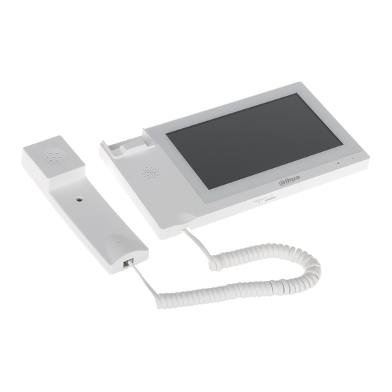
Step 2 Fix installation bracket onto 86 box with screws. Step 3 Put the device into installation bracket from top down. Installation with 86 box Figure 2-2 2.1.3 Desktop Installation with Bracket Install the device with bracket on the desktop, which only applies to handset VTH. Take “VTH5221E-H”... -
Page 13: Debugging
Figure 2-3 Desktop installation with bracket Debugging Carry out debugging to ensure that the device can realize basic network access, call and monitoring functions after installation. Before debugging, please check whether the following work has been completed. Check whether there is short circuit or open circuit. Power on the device only after the ... - Page 14 Figure 2-4 Device initialization According to interface prompt, enter “Password” and “Confirm Password”, and click Step 2 “Next”. Select “Email” and enter your Email address. This Email address is used to reset the password, so it is recommended that it should be set. Step 3 Enter default address in the browser to login WEB interface.
- Page 15 Figure 2-6 Device properties Select system type as “TCP/IP”. Click “OK” to save the settings. Reboot the device manually, or wait for auto reboot and put the settings into effect. Login WEB interface again; select “Network Setting > SIP Server”. Step 7 The system displays “SIP Server”...
- Page 16 Figure 2-8 SIP server (2) This VTO works as SIP server. Select “SIP Server Enable”, and click “OK” to save config. The VTO reboots automatically. Another VTO or platform works as SIP server. Set parameters by reference to Table 2-1 and click “OK”. The VTO reboots automatically.
- Page 17 Figure 2-9 VTO No. management Click “Add”, set outdoor station parameters by reference to Table 2-2 and click “OK”. Step 10 Repeat this step to add other outdoor stations in the group. Table 2-2 VTO No. management description Parameter Description VTO No.
-
Page 18: Vth Settings
Parameter Description Nick Name Set VTH room number. VTH room number consists of 1~6 numbers, letters, or their combinations.. It shall be consistent with room number configured at VTH. Room No. When there are master VTH and extensions, to realize group call function, master VTH short no. - Page 19 Step 3 Press [Setting] for more than 6 seconds, enter the password set during initialization, and click [OK]. Click [Network]. Step 4 The system displays “Network” interface, as shown in Figure 2-12 or Figure 2-13. IP addresses of VTH and VTO shall be in the same network segment. Otherwise, VTH will fail to obtain VTO info after configuration.
- Page 20 WLAN Press to enable Wi-Fi function. The system displays available Wi-Fi list, as shown in Figure 2-14. Figure 2-14 Network (3) Connect Wi-Fi. The system has 2 access ways as follows. At “WLAN” interface, select Wi-Fi, click “Wireless IP” tab to enter “Local IP”, ◇...
- Page 21 Figure 2-15 VTH Config Be used as a master VTH. Enter “Room No.” (such as 9901 or 101#0) and press “OK” to save. “Room no.” shall be the same with “VTH Short No.”, which is set when adding VTH at WEB interface.
- Page 22 Figure 2-16 SIP server Set parameters of SIP server by reference to Table 2-4. Table 2-4 SIP server description Parameter Description When the platform works as SIP server, server IP is IP address of the platform. Server IP When VTO works as SIP server, server IP is IP address of the VTO.
-
Page 23: Debugging Verification
Figure 2-17 VTO Config Step 8 Add VTO or fence station. Add main VTO. Enter “Main VTO Name”, “VTO IP Address”, “User Name” and “Password”. Switch the “Enable Status” to be “User Name” and “Password” shall be consistent with WEB login user name and password of VTO. -
Page 24: Vth Monitors Vto
Figure 2-18 Call VTH 2.3.2 VTH Monitors VTO VTH is able to monitor VTO, fence station or IPC. Take “VTO” for example. Select “Monitor > Door”, as shown in Figure 2-19. Select the VTO to enter monitoring image, as shown in Figure 2-20. The following figure means that SD card has been inserted into VTH. - Page 25 Figure 2-20 VTH monitors VTO (2)
-
Page 26: Appendix 1 Cybersecurity Recommendations
IP video surveillance is not immune to cyber risks, but taking basic steps toward protecting and strengthening networks and networked appliances will make them less susceptible to attacks. Below are some tips and recommendations from Dahua on how to create a more secured security system. - Page 27 Change Default HTTP and Other Service Ports We suggest you to change default HTTP and other service ports into any set of numbers between 1024~65535, reducing the risk of outsiders being able to guess which ports you are using. Enable HTTPS We suggest you to enable HTTPS, so that you visit Web service through a secure communication channel.
- Page 28 The network should be partitioned and isolated according to the actual network needs. If there are no communication requirements between two sub networks, it is suggested to use VLAN, network GAP and other technologies to partition the network, so as to achieve the network isolation effect. ...
Need help?
Do you have a question about the VTH5221 Series and is the answer not in the manual?
Questions and answers