Dahua VTH1550CHW-2 User Manual
2-wire
Hide thumbs
Also See for VTH1550CHW-2:
- User manual (109 pages) ,
- User manual (105 pages) ,
- User manual (93 pages)
Table of Contents
Advertisement
Advertisement
Table of Contents

Related Manuals for Dahua VTH1550CHW-2


Summary of Contents for Dahua VTH1550CHW-2
- Page 1 2-Wire VTH1550CHW-2 User’s Manual V1.0.0...
-
Page 2: Table Of Contents
Table of Contents General Introduction ......................4 1.1 Network ..........................4 1.2 Front Panel .......................... 5 1.3 Rear Panel ........................... 6 Installation .......................... 7 2.1 Install Device ........................7 2.1.1 Screw ..........................7 2.1.2 Steps ..........................7 2.2 Cable Connection......................... 8 2.3 Basic Config ......................... - Page 3 Important Safeguards and Warnings Please read the following safeguards and warnings carefully before using the product in order to avoid damages and losses. Note: Do not expose the device to lampblack, steam or dust. Otherwise it may cause fire or ...
-
Page 4: General Introduction
1 General Introduction 1.1 Network Here introduces application of VTH, and please read the following contents before installation. See Figure 1- 1 Villa Networking 1 and Figure 1- 2 Villa Networking 2. Figure 1- 1 Villa Networking 1 1 VTO and 4 VTH (maximum) are connected via 2-pin cable for networking. When visitor calls the resident via VTO, resident may unlock door from any one master VTH or extension. -
Page 5: Front Panel
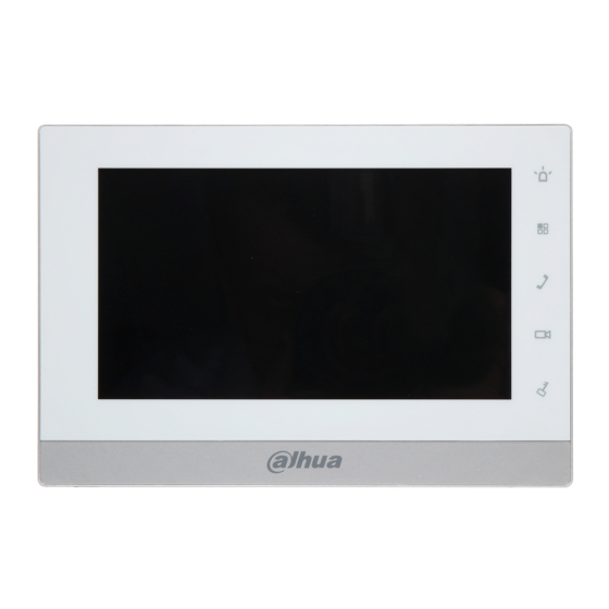
1.2 Front Panel Figure 1- 3 Name Note Emergent call to center. Press this button to return to main menu. Under calling, status, press this button to answer call. During a call, press this button to hang up. Monitor VTO video. During incoming call, calling, monitoring status, press this button to unlock. -
Page 6: Rear Panel
1.3 Rear Panel Figure 1- 4 Name Note 6-ch alarm in and 1-ch alarm out, refer to label for Alarm port details. 3 groups of 2-wire ports, may connect to power, 2-Wire port VTH, VTO or converter module. -
Page 7: Installation
2 Installation 2.1 Install Device This device support direct installation, as not digging exit hole of wiring on wall and all wirings come out from side. Warning: Avoid installation in poor environment, such as condensation, high temperature, oil stain, dust, corrosion or direct sunlight. -
Page 8: Cable Connection
Figure 2- 1 2.2 Cable Connection Please see Ch 1.3. 2.3 Basic Config After config, it will have talk function. 2.3.1 Config Step 1. In Project Settings interface, select System Settings>Project Settings and enter password (002236) to enter Project Settings interface. See Figure 2- 2. - Page 9 Figure 2- 2 Local Step 2. If the VTH is master VTH, then select Master, and fill in room no. Step 3. If the VTH is extension VTH, then select extension and fill no. In host IP, fill in IP of master VTH, so extension VTH will be automatically sync with host user config.
- Page 10 Figure 2- 4 Step 5. Press , and press Call button to go down. Fill in extension VTO name, extension VTO IP address. Set enable status to ON. You can add more than one extension VTO. See Figure 2- 5. Figure 2- 5 Step 6.
-
Page 11: Result Verification
2.3.2 Result Verification VTO call VTH via room no. VTH pops up monitoring video and operation buttons. You can accept, hand up or unlock via VTH. -
Page 12: Product Function
3 Product Function 3.1 Basic Function 3.1.1 Main Menu Main menu includes four options, as Video Talk, Security, Message, and Settings. Figure 3- 1 Icon Name Note Network It means network connection is normal. connection icon It means device does not connect to any connected VTO. -
Page 13: Video Talk
3.1.2 Video Talk In main menu, click Video Talk to enter Video Talk interface. 3.1.2.1 Call User This function is used for VTH to call VTH. Step 1. Click , Input room no. of user to call (i.e. Building 1, Unit 1, Room 101 is 1-1-101), press icon to call. -
Page 14: Security
3.1.2.3 2.1.2.3 Call History Click , you can view missed call, answered call and called call. See Figure 3- 3. Figure 3- 3 3.1.2.4 Management Center Click or press Emergency button, and it is to call MGT center. 3.1.3 Security In main menu, click Security to enter Security interface. - Page 15 Figure 3- 4 Step 2. Click Set, input password, to enter area setting interface. See Figure 3- 5. Note: The entry password is user password. Default password is 123456, please see Ch 3.1.6. Figure 3- 5 You can set bypass and delete for 4~6 channels to disable area for one time or long-term.
-
Page 16: Info Search
3.1.3.2 Alarm History Click , and it records alarm time, area no., and event. Meantime, alarm info will be simultaneously uploaded to management platform. When each channel has alarm, there will be a 15s alarm locally, plus a pop-up alarm interface. 3.1.3.3 Mode Setup Click , set area alarm mode, including Out mode, In mode, Sleep mode... -
Page 17: System Settings
Figure 3- 7 3.1.5 System Settings In main interface, click System Settings to enter system settings interface. You can set VTH screen brightness, incoming call ring, talk time, DND (do not disturb) time and etc. 3.1.5.1 User Settings Click on , you can set password, ring, talk, DND, local IPC, clean, touch ring, SD card and snapshot plus restore default settings. - Page 18 Figure 3- 8 Password Step 1. Click on Password. You can set user password, unlock password, arm password and anti-hijack password. See Figure 3- 9. Figure 3- 9 User password initially is 123456. Unlock password initially is null. ...
- Page 19 Note: Some series has the same password for arming and disarming. Step 2. Click on OK when you complete. Display Click on Display. You can set screen brightness and screensaver via Ring Click on Ring. You can set call ring and alarm ring via Talk Step 1.
- Page 20 Click on DND to set do not disturb time. Unit is hour. Local IPC Step 1. Click on Local IPC. You can set IPC name, address, username and password. See Figure 3- 11. Figure 3- 11 Step 2. Click on Save. Step 3.
-
Page 21: Unlock
3.1.5.3 Introduction Click on , you can view this product and problems might encounter during usage. 3.2 Unlock When VTH is being called, monitored, in call status, press unlock button or unlock icon on VTH to remotely unlock door. 3.3 Arm/Disarm Disarm Status Press arm icon in homepage, select one mode (out, in, sleep and custom). -
Page 22: Screen Calibration
password is 123456.). If the password is correct, system will say disarmed successfully. If the password is incorrect, system will ask you to try again. Note: About hot to modify arm/disarm password, please refer to Ch 3.1.6. 3.4 2.4 Screen Calibration The product is calibrated before shipped out from factory, and if you want to calibrate the screen, press unlock+arm/menu button to enter calibration interface. -
Page 23: Appendix 1 Technical Specification
Appendix 1 Technical Specification Model VTH1550CHW-2 System Main Processor Built-in microcontroller Operating Built-in LINUX system System Video Video Compression H.264 Standard Video 800×480 Resolution Audio Input All-direction microphone Output Built-in loudspeaker Bidirectional Support bidirectional talk Talk Display Screen 7 inch TFT full real color... -
Page 24: Appendix 2 Toxic Or Hazardous Materials Or Elements
Appendix 2 Toxic or Hazardous Materials or Elements Toxic or Hazardous Materials or Elements Component Name Cr VI PBDE Circuit Board ○ ○ ○ ○ ○ ○ Component ○ ○ ○ ○ ○ ○ Device Case ○ ○ ○ ○ ○...
Need help?
Do you have a question about the VTH1550CHW-2 and is the answer not in the manual?
Questions and answers