Dahua VTH5222CH User Manual
2-wire
Hide thumbs
Also See for VTH5222CH:
- User manual (109 pages) ,
- Quick start manual (28 pages) ,
- User manual (105 pages)
Table of Contents
Advertisement
Advertisement
Table of Contents

Related Manuals for Dahua VTH5222CH


Summary of Contents for Dahua VTH5222CH
- Page 1 2-Wire VTH5222CH User’s Manual V1.0.0...
-
Page 2: Table Of Contents
Table of Contents General Introduction ....................5 1.1 Front Panel ....................... 5 1.2 Rear Panel ........................ 5 Installation ........................ 7 2.1 Install Device ......................7 2.1.1 Metal Embedded Case ................... 7 2.1.2 Direct Installation ....................8 2.2 Cable Connection ..................... 9 Basic Config ...................... - Page 3 4.6.4 Alarm Record ....................... 42 4.7 Info Search ......................42 4.8 Unlock ........................43 Appendix 1 Technical Specifications ................44...
- Page 4 Important Safeguards and Warnings Please read the following safeguards and warnings carefully before using the product in order to avoid damages and losses. Note: Do not expose the device to lampblack, steam or dust. Otherwise it may cause fire or ...
-
Page 5: General Introduction
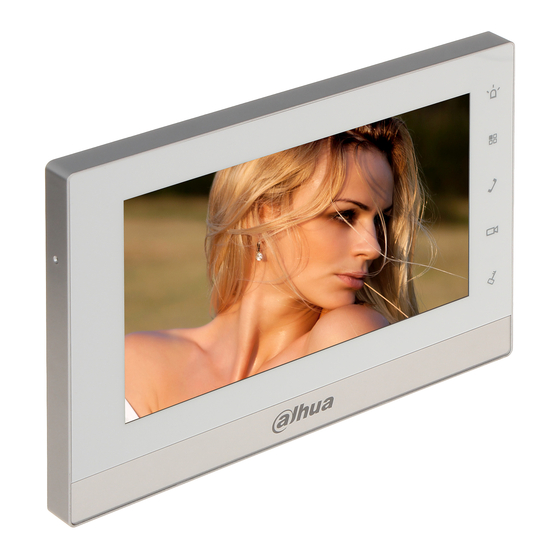
1 General Introduction 1.1 Front Panel See Figure 1-1. Figure 1-1 Parameter Note Emergent call to center. Arm/Menu Click this button to return to main menu. Under calling, status, click this button to answer call. During Call a call, click this button to hang up. Monitor Monitor VTO video. - Page 6 Figure 1-2 Port Note Alarm input 1. Alarm input 2. Alarm input 3. GND. Alarm input 4. Alarm input 5. 12-pin Port Alarm input 6. GND. RS485A port. RS485B port. Alarm output port COM(standard N/A). Alarm output port NO(standard N/A). Network Port Plug in RJ45 Ethernet cable Power Port...
-
Page 7: Installation
2 Installation 2.1 Install Device Warning: Avoid installation in poor environment, such as condensation, high temperature, oil stain, dust, corrosion or direct sunlight. After device is plugged to power, if you find any abnormal phenomenon, you shall immediately unplug network cable and cut power supply. You may re-plug in power after troubleshooting. -
Page 8: Direct Installation
Figure 2-1 2.1.2 Direct Installation Direct installation is to pull all wiring from side of device without digging holes on wall for wiring. Step 1. Fix installation bracket on wall with screw. Step 2. Fix device on installation bracket and buckle it. See Figure 2-2. -
Page 9: Cable Connection
Figure 2-2 2.2 Cable Connection Please see Ch 1.2. -
Page 10: Basic Config
3 Basic Config Quickly configure VTH and VTO to fulfill real-time talk, monitor and etc. Note: In Project Setup page (for engineer only), password to enter is 888888. 3.1 Networking See Figure 3-1. Figure 3-1 3.2 Device Config Step 1. In Project Settings interface, select System Settings>Project Settings. Step 2. - Page 11 Figure 3-2 Step 3. Set VTH room no. Warning: VTH room no. must match VTH shirt no. of corresponding VTO WEB. If this VTH is master VTH. Fill in room no. Click OK to save. If this VTH is extension, click Master, select Extension. Fill in room no., and master IP.
- Page 12 Figure 3-3 Click OK to save. Step 4. Set VTH network. Click Network, system shows Network interface. Select static IP, manually enter device IP, subnet mask, gateway and etc. Select DHCP, auto get device IP, subnet mask, gateway and etc. Note: Telnet server is ON, debugging personnel can login via telnet+IP to view VTH config.
- Page 13 Figure 3-4 If you want to add extension VTO, you can click to page down. Fill in extension VTO name, extension VTO IP address. Set enable status to ON. You can add more than one extension VTO. See Figure 3-5. Note: You can add more than one VTO if you need.
-
Page 14: Config Complete
3.3 Config Complete After config is complete, main VTO call VTH. VTH pops up monitor video and operation buttons. See Figure 3-6. Figure 3-6 Icon Name Note Incoming call, click to accept Accept` call. Incoming call, click to hang Hang up VTH in calling status, click Unlock unlock corresponding VTO... - Page 15 Icon Name Note monitor VTO. Volume Adjust VTH volume. Chart 3-1...
-
Page 16: Product Function
4 Product Function 4.1 Homepage Product homepage includes four menu options, as Video Talk, Security, Message, and Settings. See Figure 4-1. Figure 4-1 Name Note Status Bar : Network connection icon. It means network connection is normal. : VTO not connected. It means device does not connect to any VTO. -
Page 17: Settings
: Missed icon. It means user has missed message. Time Show date, week and time. Video Talk In this page you can view all call records. Alarm Set zone type, status, delay time, zone switch and etc. of each zone. Message You can view, delete and clear announcements and alarm info, plus guest message and etc. - Page 18 4.2.1.1 Password You can go to Settings>User Settings>Password Settings interface, set username password, unlock password, arm/disarm password and duress(anti-hijack) password. Step 1. Click Settings>User Settings>Password Settings. See Figure 4-3. Figure 4-3 Step 2. Select password type. Step 3. Enter old password, new password and confirm password. Note: ...
- Page 19 4.2.1.3 Ring You can go to Settings>User Settings>Ring Settings, select incoming call ring and alarm ring. You can set call ring, alarm ring and volume via 4.2.1.4 Talk You can go to Settings>User Settings>Talk Settings. You can set VTH ring time, VTH ring time, VTH talk time, VTH talk time, monitor time and VTO message time via .See Figure 4-4.
- Page 20 4.2.1.5 DND Select Settings>User Settings>DND. See Figure 4-5. Note: Effective immediately after setup. DND is disabled by default. DND hour is 0H by default. After DND is ON, incoming call ring will not be prompted, and you can view missed call record in Video Talk<Record<Missed.
- Page 21 Figure 4-6 Step 2. Set IPC. Parameter Note IPC Name Enter IPC name. Network Address Enter planned IPC IP address Username Enter login IPC WEB username and password Password Port IPC port no. As local protocol and Onvif protocol, please select Protocol accordingly.
- Page 22 Click to continue to add local IPC, up to 8. 4.2.1.7 Clean Select Settings>User Settings>Clean. Click on Clean to lock screen and now you can clean the screen. 4.2.1.8 SD Card Note: Only when you insert SD card, this function is shown. ...
-
Page 23: Project Settings
4.2.2 Project Settings Click on , this function is for installer user only. The entry password is 888888. 4.2.2.1 Product Info Warning VTH room no. must match VTH short no. on VTO WEB. You can set local VTH room no. in Setting>Project Settings>Product Info. - Page 24 Figure 4-8 Step 2. Click Master. See Figure 4-9. Figure 4-9 Step 3. Fill in room no. and host IP. Note: Part of extension info will be auto synced with master VTH, and cannot be modified. Step 4. Click OK to save.
- Page 25 4.2.2.2 Network You can select Settings>Project Settings>Network>, set VTH device network. Step 1. Select Settings>Project Settings>Network. Step 2. Select method of network. Select Static, manually enter device IP, subnet mask, gateway and etc. Select DHCP, auto get network parameters. Note: Telnet server is ON, debugging personnel can login via telnet+IP view to view VTH config.
- Page 26 Figure 4-11 4.2.2.4 IPC Info VTH device auto sync with IPC info added on VTO (max 24), used for VTH to monitor the IPC. You can view in Settings>Project Settings>IPC Info. 4.2.2.5 Search Device Note Our 2-wireVTH and villa VTO are in the same segment by default, if you have modified VTH IP address, please set it back to default IP.
- Page 27 Figure 4-12 Step 2. Select villa VTO, click Modify IP. See Figure 4-13. Note: When modify IP is grey, means the device is unit VTO, cannot change IP. Figure 4-13 Step 3. Fill in IP address, subnet mask and gateway of villa VTO, click OK.
-
Page 28: Time Settings
Step 4. Click Add. Step 5. Fill in VTO name, set status to ON. You also can click to page down. The villa VTO is set as sub VTO, set status to ON. See Figure 4-14. Figure 4-14 Step 6. Click OK. Now, villa VTO can call the VTH. 4.2.2.6 Default You can go to Settings>Project Settings>Default, restore all config info to default in Project Settings interface. -
Page 29: Introduction
Figure 4-15 4.2.4 Introduction You can select Settings>Introduction, see Figure 4-16. Figure 4-16 4.2.5 Info Initialization You can go to Settings>Initialization interface. -
Page 30: Call
Note: This is for apartment system. Step 1. Select Settings>Initialization. See Figure 4-17. Figure 4-17 Step 2. Enter building, unit, and room no. You can select extension, enter building, unit, room no. and host IP to add VTH extension. Step 3. Click OK. 4.3 Call Note: ... - Page 31 Figure 4-18 Parameter Note ,ON means alarm output is enabled, and OFF means Slide Alarm Output alarm output is disabled. When other device calls VTH, it will link to 1-ch alarm output on VTH. ,ON means to enable inter-resident call. OFF means to Slide disable inter-resident call.
-
Page 32: Contact
4.3.1.2 Call via Contact Warning: You must add contact first before you can call designated resident via contact. Please refer to Ch 4.3.2. Step 1. Select Video Talk>Call Resident. Step 2. Click to open Contacts. Step 3. Select resident you want to call, click to call. - Page 33 You also can click any block in Contact interface, device shows user info interface. Figure 4-20 Step 4. Enter contact name and room no. Step 5. Click OK to add contact. See Figure 4-21. Figure 4-21...
-
Page 34: Call Record
4.3.2.2 Call Contact In Contact interface, select user you want to call, click Call. 4.3.2.3 Modify Contact In Contact interface, select user you want to modify, click Edit. 4.3.2.4 Delete Contact In Contact interface, select user you want to delete, click Delete. 4.3.2.5 Clear Contact If you want to cleat all contracts, in Contact interface, click Clear and confirm in pop-up box. -
Page 35: Sos Call
4.3.3.1 Call Back If you want to call back, select number to call, click Call. 4.3.3.2 Storage If you want to store contact, select number to store, click Save. Enter contact name. See Figure 4-23. Figure 4-23 4.3.3.3 Delete, Clear You can select call record, click Delete to delete it. -
Page 36: Monitor
Figure 4-24 4.5 Monitor VTH can monitor VTO or any specific IP camera. Under monitor status, press on front panel to call VTO. When it calls VTO, call will be auto accepted. For example, monitor VTO: Step 1. Select Video Talk>Monitor>VTO, or click on device front panel. -
Page 37: Alarm
Step 2. Select VTO to monitor. See Figure 4-26. Figure 4-26 Icon Note Switch to monitor previous channel or next channel VTO. Unlock key, can remotely unlock VTO. Record, click to start record, click again to end record. Snapshot, click to snapshot two pictures. - Page 38 Note: Only under disarm status can set alarm zone. You select Alarm>Zone Status interface, to set each zone type, status, delay time and etc. Step 1. Select Alarm>Zone Status. See Figure 4-27. Figure 4-27 Parameter Note Setup Set zone, including zone type, NO/NC, alarm, entry delay and exit delay. Bypass Zone is shielded during this arming, when device disarms, zone will restore status before bypass.
-
Page 39: Mode Setting
Figure 4-28 Step 5. Ser zone type, NO/NC, alarm, entry delay and exit delay. Parameter Note Zone No. Set sensor zone no., not changed by default. Zone Type According to each zone sensor type, select zone type, including IR, gas, smoke, SOS and etc. -
Page 40: Arm/Disarm
Figure 4-29 4.6.3 Arm/Disarm Arm: When arm is enabled, device enter arming status. When detects alarm, device will alarm and upload alarm. Disarm: enabled, device exit arming status. 4.6.3.1 Arm Step 1. In homepage menu, click . See Figure 4-30. - Page 41 Figure 4-30 Step 2. Select mode. Step 3. In pop-up interface, enter arm password. Device will beep, which means armed successfully. Note: Initial arm password is 123456, and you can change this password in Settings>User Settings>Password Settings. 4.6.3.2 Disarm Step 1. In homepage, click Disarm icon. Step 2.
-
Page 42: Alarm Record
4.6.4 Alarm Record When alarm occurs, alarm into not only uploads to Alarm>Alarm Record interface, but also upload to MGT center, and beep for 15s, pop up alarm page. You can go to Alarm>Alarm Record interface, to view, delete or cleat alarm info. See Figure 4-31. -
Page 43: Unlock
Figure 4-32 4.8 Unlock VTH which is being called, monitored, or calling, press Unlock button on device, to remotely open VTO lock. -
Page 44: Appendix 1 Technical Specifications
Appendix 1 Technical Specifications VTH5222CH System Main Embedded micro controller Processor Embedded LINUX OS Video Video Compression H.264 Standard Video 800×480 Resolution Front None Camera Audio Input Omni directional MIC Output Built-in speaker Talk Bidirectional audio talk Display Screen 7 inch TFT full color screen... - Page 45 Note: This manual is for reference only. Slight difference may be found in user interface. All the designs and software here are subject to change without prior written notice. All trademarks and registered trademarks are the properties of their respective owners.
Need help?
Do you have a question about the VTH5222CH and is the answer not in the manual?
Questions and answers