Table of Contents
Advertisement
CTRLMax
Supplement
S OLO 80, 110, 155, 175 , 2 5 0, 2 99, 399 &
EXCE LLENCE 110
TC 24 0-299
SOLO 110-155-19 9 & COM BI 1 55 -1 99
This document is intended to be used
by a factory trained and qualified
heating contractor or service technician
only. Read all Instructions within this
document and within the relevant Boiler
Installation and Maintenance Manual
222171 A01 - July 2019
2019-15
WARNING
before proceeding. It is recommended
to follow the procedures in the steps
given. Skipping or missing procedural
steps could result in substantial property
damage, serious injury, or death.
Instinct
Instinct
DHW
DHW
DHW Demand
DHW Demand
O R I G I N A L
I N N O V A T O R S
T H E
Advertisement
Table of Contents

Related Manuals for TriangleTube CTRLMax Prestige Series


Summary of Contents for TriangleTube CTRLMax Prestige Series
- Page 1 CTRLMax Supplement Instinct Instinct DHW Demand DHW Demand S OLO 80, 110, 155, 175 , 2 5 0, 2 99, 399 & EXCE LLENCE 110 TC 24 0-299 SOLO 110-155-19 9 & COM BI 1 55 -1 99 WARNING This document is intended to be used before proceeding.
- Page 2 INTENTIONALLY LEFT BLANK...
-
Page 3: Table Of Contents
TABLE OF CONTENTS CHAPTER 1 - OPERATING INFORMATION ................. 1 1.1. General ............................. 1 1.1.1 PRESTIGE and HEATMASTER Control Panel Description ..........1 1.1.2 Main settings of the PRESTIGE and HEATMASTER CTRLMax Display ......1 1.1.3 INSTINCT Control Panel Description ...................2 1.1.4 Main settings of INSTINCT CTRLMax Display ..............3 1.1.5... - Page 4 TABLE OF CONTENTS 3.5. DHW Setpoint ..........................14 3.6. DHW on Differential ........................14 3.7. DHW Storage Adder ........................15 3.8. DHW Post Pump Time ........................15 3.9. DHW Priority Timeout ........................15 3.10. DHW Priority ..........................15 3.11. DHW Call Blocking ........................16 3.12.
- Page 5 TABLE OF CONTENTS CHAPTER 6 - MANUAL OPERATION ................51 CHAPTER 7 - RESET ALL SETTINGS ................53 7.1. Factory CTRLMax Settings ......................53 CHAPTER 8 - CASCADE .....................55 8.1. Operating Principles of an CTRLMax-Controlled Cascade (Prestige and INSTINCT only) ..55 8.2.
- Page 6 TABLE OF ILLUSTRATIONS Fig. 1 - PRESTIGE and HEATMASTER Control Panel ................1 Fig. 2 - INSTINCT Control Panel ........................2 Fig. 3 - System Piping with Solo Preset Config. 1 ................. 29 Fig. 4 - System Pipingwith Solo Preset Config. 2 ................. 30 Fig.
- Page 7 PRODUCT AND SAFETY INFORMATION IMPORTANT SAFETY INFORMATION WARNING Triangle Tube accepts no liability for any damage, injury, or loss of life resulting from incorrect installation, alteration of any factory supplied This document is intended to be used by a parts, or the use of parts or fittings not specified by factory trained and qualified heating con- Triangle Tube.
- Page 8 INTENTIONALLY LEFT BLANK...
-
Page 9: Chapter 1 - Operating Information
CHAPTER 1 - OPERATING INFORMATION 1.1. General 2. Installer button - Allows the installer to open the ac- cess code window of the CTRLMax controller and set The ControlMax (CTRLMax) system control is designed up the system once the code has been entered. to be flexible yet easy to use. -
Page 10: 1.1.3 Instinct Control Panel Description
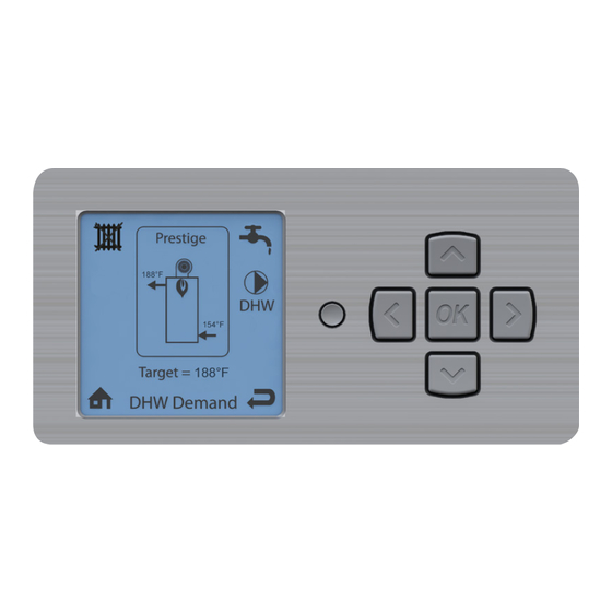
CHAPTER 1 - OPERATING INFORMATION Instinct Instinct DHW Demand DHW Demand Fig. 2 - INSTINCT Control Panel NOTICE 1.1.3 INSTINCT Control Panel Description 1. CTRLMax LCD Display - It is the setup interface of • When shutting down using the soft key, the appliance and indicates the parameter values, the the appliance will not react to any heat de-... -
Page 11: Main Settings Of Instinct Ctrlmax Display
CHAPTER 1 - OPERATING INFORMATION 1.1.5 Main Icons of CTRLMax display The Main Menu (EZSetup, no code required) can be ac- cessed from the Home Screen by touching the center Central Heating - indicates information related soft key . More information can be found in the In- to the CH circuit. -
Page 12: Ctrlmax Installer Menu Structure
CHAPTER 1 - OPERATING INFORMATION 1.3. CTRLMax Installer Menu Structure Manual Operation – The burner and circulators can be manually enabled for testing. The Installer Menu is divided into four sections Cascade – Allows the installer to setup, adjust and CH &... -
Page 13: Chapter 2 - Ch Settings
CHAPTER 2 - CH SETTINGS Installer Code CH & DHW Settings NOTICE Navigate on the screen using the UP, DOWN, LEFT and RIGHT keys, then the validate a selection with the OK key. To increase/decrease values, use the UP and DOWN or LEFT and RIGHT keys, according to the situation and validate with OK. -
Page 14: Ch Maximum Capacity
CHAPTER 2 - CH SETTINGS CH Settings Demand Type screen menu Thermostat & Outdoor Curve – A central heating call from a dry contact switch will enable the appliance and the setpoint will vary with the outdoor Heating Settings temperature for central heating calls. Heating Operation Enabled Demand... -
Page 15: Ch Minimum Capacity
CHAPTER 2 - CH SETTINGS CH Settings CH Minimum Capacity sets the lowest limit of the CH capac- Heating Settings CH Minimum Capacity ity. The appliance capacity can be defined by adjusting this Heating Operation Enabled value and the CH Maximum capacity. It is therefore possible to Demand Thermostat &... -
Page 16: Outd. Curve Coldest Day
CHAPTER 2 - CH SETTINGS CH Settings Outdoor Curve Outdoor Curve Coldest Day is the coldest outdoor design Heating Settings Coldest Day temperature of the heating system when an Outdoor Curve CH Maximum Capacity 100% 10°F CH Minimum Capacity option is chosen in Demand Type. This setting is not applicable Abs. -
Page 17: Ch2 Min. Setpoint
CHAPTER 2 - CH SETTINGS CH Settings CH2 Minimum Setpoint is the minimum setpoint for a CH2 Min. Heating Settings Setpoint CH2 heating call when an Outdoor Curve option is chosen CH1 Min. Setpoint 80°F 80°F Outdoor Curve Coldest Day 10°F in Demand Type. -
Page 18: Freeze Protection
CHAPTER 2 - CH SETTINGS The Freeze Protection menu allows the feature to be enabled CH Settings and disabled. The built-in frost protection mechanism activates the system pumps as soon as the flow temperature [NTC1 probe] drops below 46°F. As soon as the flow temperature is at Heating Settings Freeze Protection 42°F, the burner starts up until the flow temperature rises above... -
Page 19: Parallel Shift Value
CHAPTER 2 - CH SETTINGS CH Settings Parallel Shift Value Parallel Shift allows the CH setpoint to be externally adjusted Heating Settings when a Constant option is chosen in Demand Type. When a Warm Weather Shutdown 0°F Constant option is chosen in Demand Type, continuous CH1 Circulation Pump Perman. - Page 20 INTENTIONALLY LEFT BLANK...
-
Page 21: Chapter 3 - Dhw Settings (Prestige, Heatmaster And Instinct Solo)
CHAPTER 3 - DHW SETTINGS (PRESTIGE, HEATMASTER AND INSTINCT SOLO) Installer Code NOTICE Navigate on the screen using the UP, DOWN, LEFT and RIGHT keys, then the validate a selection with the OK key. To increase/decrease values, use CH & DHW Settings the UP and DOWN or LEFT and RIGHT keys, according to the situation and validate with OK. -
Page 22: Dhw Maximum Capacity
CHAPTER 3 - DHW SETTINGS (PRESTIGE, HEATMASTER AND INSTINCT SOLO) DHW Maximum Capacity limits the maximum DHW capac- DHW Setting ity. The appliance capacity can be defined by adjusting this value, 100% means Maximum DHW output, 0% means mini- mum DHW output. It is therefore possible to adjust the DHW capacity to the installation needs. -
Page 23: Dhw Storage Adder
CHAPTER 3 - DHW SETTINGS (PRESTIGE, HEATMASTER AND INSTINCT SOLO) DHW Setting DHW Storage Adder is used to compute the appliance set- DHW Setting DHW Storage Adder point when the Sensor option is chosen in Demand Type. The Demand Sensor 28°F DHW maximum capacity 100%... -
Page 24: Dhw Call Blocking
CHAPTER 3 - DHW SETTINGS (PRESTIGE, HEATMASTER AND INSTINCT SOLO) DHW Setting DHW Call Blocking sets the minimum time between burner firings DHW Setting DHW Call Blocking for domestic hot water calls. At the completion of a burner firing, the DHW on Di erential 6°F 0 min. -
Page 25: Antilegionella Function
CHAPTER 3 - DHW SETTINGS (PRESTIGE, HEATMASTER AND INSTINCT SOLO) DHW Setting The Antilegionella Function ensures that an Indirect Water DHW Setting Antilegionella Function Heater is heated at least once per week to prevent the growth of DHW Post Pump Time 2 min Enabled Legionella bacteria. - Page 26 INTENTIONALLY LEFT BLANK...
-
Page 27: Chapter 4 - Dhw Settings (Instinct Combi Only)
CHAPTER 4 - DHW SETTINGS (INSTINCT COMBI ONLY) Installer Code NOTICE Navigate on the screen using the UP, DOWN, LEFT and RIGHT keys, then the validate a selection with the OK key. To increase/decrease values, use CH & DHW Settings the UP and DOWN or LEFT and RIGHT keys, according to the situation and validate with OK. -
Page 28: Dhw On Differential
CHAPTER 4 - DHW SETTINGS (INSTINCT COMBI ONLY) DHW Setting DHW On Differential sets how far the DHW temperature of DHW Setting DHW On Di erential the storage tank must fall below the DHW Setpoint to create DHW Operation Enabled 6°F DHW Setpoint 140°F... -
Page 29: Dhw Priority Timeout
CHAPTER 4 - DHW SETTINGS (INSTINCT COMBI ONLY) DHW Setting DHW Setting DHW Priority Timeout DHW Priority Timeout allows the installer to enter an optional DHW Setpoint 140°F time limit that a domestic hot water call has priority over a central DHW on Di erential 18°F heating call when DHW Priority is set to Enabled. - Page 30 INTENTIONALLY LEFT BLANK...
-
Page 31: Chapter 5 - Boiler Settings
CHAPTER 5 - BOILER SETTINGS Installer Code NOTICE Navigate on the screen using the UP, DOWN, LEFT and RIGHT keys, then the validate a selection with the OK key. To increase/decrease CH & DHW Settings values, use the UP and DOWN or LEFT and RIGHT keys, according to the situation and validate with OK. -
Page 32: Pump Settings
CHAPTER 5 - BOILER SETTINGS Boiler Settings The Pump Settings menu allows to choose the right pump Boiler Settings configuration to the chosen hydraulic configuration. Model Prstige Solo Lockout Temp. 210°F [99°C] The Current Pump Config indicates which configuration is Modbus Address 0=BCST Pump settings... - Page 33 CHAPTER 5 - BOILER SETTINGS Boiler Settings Boiler Settings Model Prstige Solo Lockout Temp. 210°F [99°C] Modbus Address 0=BCST Pump Settings Pump settings Ignition Level 3500rpm Current Pump Con g Modi ed Mix zone high limit 45°C Preset Pump Con g Flexible Pump Con g Pump PWM minimum Flexible Pump Con g...
-
Page 34: Error Relay
CHAPTER 5 - BOILER SETTINGS Boiler Settings Boiler Settings Model Prstige Solo Lockout Temp. 210°F [99°C] Modbus Address 0=BCST Pump settings Ignition Level 3500rpm Pump Settings Mix zone high limit 45°C Current Pump Con g Modi ed Preset Pump Con g Flexible Pump Con g Pump PWM minimum There are three possible selections to activate the Error Re-... -
Page 35: Mix Zone High Limit
CHAPTER 5 - BOILER SETTINGS Boiler Settings The Mix zone high limit setting allows to limit the maxi- Mix zone high limit Boiler Settings mum temperature in the mixed circuit. The function works Prestige Model Prestige Solo 114°F like an Overheat Cut-off Activation of the limit and will cause Lockout Temp. -
Page 36: Altitude
CHAPTER 5 - BOILER SETTINGS Boiler Settings The Altitude parameter allows to define the altitude at Altitude Boiler Settings which your system is installed and compensate for the pos- Pump settings 0 ft Ignition Level 3500rpm sible change in air density when in higher altitude. The alti- Mix zone high limit 114°F tude parameter can be adjusted in steps of 984 ft. -
Page 37: Fig. 3 - System Piping With Solo Preset Config. 1
CHAPTER 5 - BOILER SETTINGS PRESTIGE SOLO - PRESET PUMP CONFIGURATION 1 Heat Call Pump 4 Pump 3 DHW Pump CH Pump Fig. 3 - System Piping with Solo Preset Config. 1... -
Page 38: Fig. 4 - System Pipingwith Solo Preset Config. 2
CHAPTER 5 - BOILER SETTINGS PRESTIGE SOLO PRESET PUMP CONFIGURATION 2 Heat Call Pump 4 Pump 3 DHW Pump CH Pump Fig. 4 - System Pipingwith Solo Preset Config. 2... -
Page 39: Fig. 5 - System Piping With Solo Preset Config. 3
CHAPTER 5 - BOILER SETTINGS PRESTIGE SOLO PRESET PUMP CONFIGURATION 3 Heat Call Pump 4 Pump 3 DHW Pump CH Pump Fig. 5 - System Piping with Solo Preset Config. 3... -
Page 40: Fig. 6 - System Piping With Solo Preset Config. 4
CHAPTER 5 - BOILER SETTINGS PRESTIGE SOLO - PRESET PUMP CONFIGURATION 4 Heat Call Pump 4 Pump 3 DHW Pump CH Pump Fig. 6 - System Piping with Solo Preset Config. 4... -
Page 41: Fig. 7 - System Piping With Solo Preset Config.5
CHAPTER 5 - BOILER SETTINGS PRESTIGE SOLO - PRESET PUMP CONFIGURATION 5 Heat Call Pump 4 Pump 3 DHW Pump CH Pump Fig. 7 - System Piping with Solo Preset Config.5... -
Page 42: Fig. 8 - System Piping With Solo Preset Config. 6
CHAPTER 5 - BOILER SETTINGS PRESTIGE SOLO - PRESET PUMP CONFIGURATION 6 Heat Call Pump 4 Pump 3 DHW Pump CH Pump Fig. 8 - System Piping with Solo Preset Config. 6... -
Page 43: Fig. 9 - System Piping With Solo Preset Config. 7
CHAPTER 5 - BOILER SETTINGS PRESTIGE SOLO - PRESET PUMP CONFIGURATION 7 Heat Call FLAME Pump 4 Pump 3 DHW Pump CH Pump ON (Mix close) ON (Mix open) NOTICE This configuration is to be used where the Low temp circuit is a micro load and the High temp circuit will run for any call on the Low temp circuit to prevent boiler cycling. -
Page 44: Fig. 10 - System Piping With Solo Preset Config. 8
CHAPTER 5 - BOILER SETTINGS PRESTIGE SOLO - PRESET PUMP CONFIGURATION 8 Heat Call Pump 4 Pump 3 DHW Pump CH Pump Fig. 10 - System Piping with Solo Preset Config. 8... -
Page 45: Fig. 11 - System Piping With Solo Preset Config. 9
CHAPTER 5 - BOILER SETTINGS PRESTIGE SOLO - PRESET PUMP CONFIGURATION 9 Heat Call FLAME Pump 4 Pump 3 DHW Pump CH Pump ON (Mix Close) ON (Mix open) NOTICE This configuration requires that the Low temp pump and High temp pump be connected in parallel to the CH pump relay. -
Page 46: Fig. 12 - System Piping With Solo Preset Config. 13
CHAPTER 5 - BOILER SETTINGS PRESTIGE SOLO - PRESET PUMP CONFIGURATION 13 Heat Call FLAME Pump 4 Pump 3 DHW Pump CH Pump ON (Mix Close) ON (Mix open) Fig. 12 - System Piping with Solo Preset Config. 13... -
Page 47: Fig. 13 - System Piping With Excellence Preset Config. 1
CHAPTER 5 - BOILER SETTINGS PRESTIGE EXCELLENCE - PRESET PUMP CONFIGURATION 1 Heat Call Pump 4 Pump 3 DHW Pump CH Pump Fig. 13 - System Piping with Excellence Preset Config. 1... -
Page 48: Fig. 14 - System Piping With Excellence Preset Config. 2
CHAPTER 5 - BOILER SETTINGS PRESTIGE EXCELLENCE - PRESET PUMP CONFIGURATION 2 Heat Call Pump 4 Pump 3 DHW Pump CH Pump Fig. 14 - System Piping with Excellence Preset Config. 2... -
Page 49: Fig. 15 - System Piping With Excellence Preset Config. 3
CHAPTER 5 - BOILER SETTINGS PRESTIGE EXCELLENCE - PRESET PUMP CONFIGURATION 3 Heat Call FLAME Pump 4 Pump 3 DHW Pump CH Pump ON (Mix Close) ON (Mix open) Fig. 15 - System Piping with Excellence Preset Config. 3... -
Page 50: Fig. 16 - System Piping With Excellence Preset Config. 4
CHAPTER 5 - BOILER SETTINGS PRESTIGE EXCELLENCE - PRESET PUMP CONFIGURATION 4 Heat Call FLAME Pump 4 Pump 3 DHW Pump CH Pump ON (Mix Close) ON (Mix Open) Fig. 16 - System Piping with Excellence Preset Config. 4... -
Page 51: Fig. 17 - Instinct Solo System Piping - Multi Zone System With Single System/Boiler Circulator
CHAPTER 5 - BOILER SETTINGS INSTINCT SOLO - PUMP SETTINGS Heat Call DHW pump CH pump Flame NOTICE Please contact Triangle Tube’s technical support for more information on the possible use of the Preset Pump Config function for this system. Z.V. -
Page 52: Fig. 18 - Instinct Solo System Piping - Indirect Water Heater Installation
CHAPTER 5 - BOILER SETTINGS INSTINCT SOLO - PUMP SETTINGS Heat Call DHW pump CH pump Flame NOTICE Please contact Triangle Tube’s technical support for more information on the possible use of the Preset Pump Config function for this system. Fig. -
Page 53: Fig. 19 - Instinct Combi System Piping - Zoning W Valves
CHAPTER 5 - BOILER SETTINGS INSTINCT COMBI - PUMP SETTINGS Heat Call DHW pump CH pump Flame NOTICE Please contact Triangle Tube’s technical support for more information on the possible use of the Preset Pump Config function for this system. Z.V. -
Page 54: Fig. 20 -Instinct Combi - System Piping - Multi Zone Valve - Single Circulator
CHAPTER 5 - BOILER SETTINGS INSTINCT COMBI - PUMP SETTINGS Heat Call DHW pump CH pump Flame NOTICE Please contact Triangle Tube’s technical support for more information on the possible use of the Preset Pump Config function for this system. Z.V. -
Page 55: Fig. 21 - Instinct Combi - System Piping - Single Zone With Single Circulator
CHAPTER 5 - BOILER SETTINGS INSTINCT COMBI - PUMP SETTINGS Heat Call DHW pump CH pump Flame NOTICE Please contact Triangle Tube’s technical support for more information on the possible use of the Preset Pump Config function for this system. Fig. -
Page 56: Fig. 22 - Instinct Combi System Piping - Single Zone System With Single System/Boiler Circulator
CHAPTER 5 - BOILER SETTINGS INSTINCT COMBI - PUMP SETTINGS Heat Call DHW pump CH pump Flame NOTICE Please contact Triangle Tube’s technical support for more information on the possible use of the Preset Pump Config function for this system. Fig. -
Page 57: Fig. 23 - Instinct Combi System Piping - Domestic Piping - Storage Tank Installation
CHAPTER 5 - BOILER SETTINGS INSTINCT COMBI - PUMP SETTINGS Heat Call DHW pump CH pump Flame NOTICE Please contact Triangle Tube’s technical support for more information on the possible use of the Preset Pump Config function for this system. Fig. - Page 58 INTENTIONALLY LEFT BLANK...
-
Page 59: Chapter 6 - Manual Operation
CHAPTER 6 - MANUAL OPERATION Installer Code Manual Operation Manual Operation FAN - Actuate the OK key while the FAN icon is highlighted to manually fire the burner and power the CH (1) circulator. Released Adjust the firing rate from 0% (Low Fire) to 100% (High Fire) using the LEFT and RIGHT keys. - Page 60 INTENTIONALLY LEFT BLANK...
-
Page 61: Chapter 7 - Reset All Settings
CHAPTER 7 - RESET ALL SETTINGS Reset All Settings allows the installer to reset all CH, DHW, Reset All Settings Reset All Settings and Cascade settings back to the default values (See below). Press OK to restore factory settings, Follow the on-screen instructions to reset all settings back any other button to keep current settings. - Page 62 CHAPTER 7 - RESET ALL SETTINGS MINIMUM MAXIMUM EZ SETUP INSTALLER DHW SETTING FACTORY DEFAULT SETTING SETTING RESET RESET Prestige Prestige HeatMaster Instinct Instinct Solo Excellence Solo Combi DHW Operation Enabled Thermostat Sensor Sensor Thermostat Demand Type — DHW Boiler Setpoint 168°F [75°C] 168°F [75°C] 168°F [75°C] 168°F [75°C] —...
-
Page 63: Chapter 8 - Cascade
CHAPTER 8 - CASCADE 8.1. Operating Principles of an CTRL- Max-Controlled Cascade (PRESTIGE and The Cascade control works as a power control on the INSTINCT only) local appliances. The system temperature is the param- eter to regulate and the local temperatures are of no PRESTIGE and INSTINCT boilers can be setup in a cas- avail, they are only used to limit the local power in case cade configuration (max. -
Page 64: Ctrlmax Cascade Menu Structure
CHAPTER 8 - CASCADE 8.3. CTRLMax Cascade menu structure the System Temperature Sensor is critical for reliable cascade operation. The type of System Temperature Sensor chosen also greatly affects the accuracy of the Cascade system temperature readings. Three types of System Temperature Sensor are available: •... -
Page 65: 8.4.3 Cascade Communication Cable
CHAPTER 8 - CASCADE 6. Actuate the white cover onto the sensor and strap the sensor to the pipe using the included wire tie. 7. Wire the sensor to terminals 3 & 4 of X5 on the con- trol module of the Master boiler. 8.4.3 Cascade Communication Cable A communication cable PACAB01 must be installed be- tween each boiler in the Cascade System. -
Page 66: 8.4.5 Line Voltage Wiring Connections
CHAPTER 8 - CASCADE 8.4.5 Line Voltage Wiring Connections 8.4.6 Cascade Autodetection • Circulator Wiring - Reference Figures 22, 24 The Cascade System must be configured after wiring is and 26 on pages 58, 60 and 62 for circulator wir- completed and any required adjustments are made in ing required for each type of Cascade System. -
Page 67: Cascade Autodetection
CHAPTER 8 - CASCADE Installer Code NOTICE Cascade Navigate on the screen using the UP, DOWN, LEFT and RIGHT keys, then the validate a selection with the OK key. To increase/decrease values, use the UP and DOWN or LEFT and RIGHT keys, according to the situation and validate with OK. -
Page 68: Cascade Info
CHAPTER 8 - CASCADE Installer Code Cascade Info provides real time operating informa- Cascade Cascade Info. tion of the Cascade System. Each line contains an in- formation item followed by its current value. Cascade Info provides the following information Cascade Info. item: Cascade Role Master... -
Page 69: Cascade Settings
CHAPTER 8 - CASCADE The Cascade Settings menu contains settings relat- Cascade Cascade Settings ed to cascade operation. Each line contains a Cascade Setting followed by its current value. Six Cascade Set- tings are displayed on the screen at one time. Scroll through Cascade Settings using the UP or DOWN keys. -
Page 70: Min. Firing Rate
CHAPTER 8 - CASCADE Cascade Settings Minimum Firing Rate is the minimum firing rate of a single Minimum Firing Rate Cascade Setting boiler in the Cascade System. The Master boiler uses this setting Stage Delay 60 sec 18 % Minimum Firing Rate to determine when boilers can be enabled and disabled. - Page 71 CHAPTER 8 - CASCADE Cascade Settings The CH / DHW Boilers setting specifies how many boilers in a CH / DHW Boilers Cascade Setting Split Cascade System will respond to a domestic hot water call. Stage Delay 60 sec Minimum Firing Rate Max.
-
Page 72: Auto Rotation
CHAPTER 8 - CASCADE Cascade Settings Through the Auto Rotation function, the number of burn- Cascade Setting Auto Rotation Stage Delay 60 sec ing hours is equalized over all appliances. Minimum Firing Rate Enabled When the function is Enabled, the appliances will all run Max. -
Page 73: Ch Integral Gain
CHAPTER 8 - CASCADE Cascade Settings CH Integral Gain allows the cascade response to be ad- Cascade Setting justed for a central heating call. CH Integral Gain has the Minimum Firing Rate Max. Firing Rate 250 kW greatest influence when the system temperature is close to CH / DHW Boilers the setpoint. -
Page 74: Dhw Prop. Gain
CHAPTER 8 - CASCADE DHW Proportional Gain allows the cascade response to Cascade Settings be adjusted for a domestic hot water call. DHW Proportion- al Gain has the greatest influence when the system tem- perature is far away from the setpoint. Adjust the DHW Prop. -
Page 75: Fig. 27 - Primary Secondary Cascade Piping
CHAPTER 8 - CASCADE Fig. 27 - Primary Secondary Cascade Piping... -
Page 76: Fig. 28 - Primary Secondary Cascade Wiring
CHAPTER 8 - CASCADE N G L System Modulation Outdoor DHW Sensor Modbus Thermostat Sensor Signal Thermostat Sensor aquastat L G N L G N L G N L G N L G N L G N PUMP 4 PUMP 3 FLAME DHW PUMP CH PUMP... -
Page 77: Fig. 29 - Reverse Return Cascade Piping
CHAPTER 8 - CASCADE Fig. 29 - Reverse Return Cascade Piping... -
Page 78: Fig. 30 -Reverse Return Cascade Wiring
CHAPTER 8 - CASCADE Master Prestige Boiler N G L System Modulation Outdoor DHW Sensor Modbus Thermostat Sensor Signal Thermostat Sensor aquastat L G N L G N L G N L G N L G N L G N PUMP 4 PUMP 3 FLAME... -
Page 79: Fig. 31 - Split Cascade System
CHAPTER 8 - CASCADE Fig. 31 - Split Cascade System... -
Page 80: Fig. 32 - Split Cascade Wiring
CHAPTER 8 - CASCADE Master Prestige Boiler N G L System Modulation Outdoor DHW Sensor Modbus Thermostat Sensor Signal Thermostat Sensor aquastat L G N L G N L G N L G N L G N L G N PUMP 4 PUMP 3 FLAME... -
Page 81: Chapter 9 - Modbus Interface
Modbus Interface CHAPTER 9 - MODBUS INTERFACE MODBUS INTERFACE The Modbus Interface allows a Building Management The Modbus Interface allows a Building Management System (BMS) to directly connect to the Prestige. System (BMS) to directly connect to the appliance. A BMS can read information from the boiler to determine its operating state, lockout status, sensor read- A BMS can read information from the boiler to deter- ings, etc. - Page 82 Modbus Interface CHAPTER 9 - MODBUS INTERFACE Table 4 - Input Registers (Read only) Table 10: Input Registers (Read Only) Address Supported Description Byte: Format Notes DEC (HEX) Commands 0 (0x0000) 0x04 Boiler Status LB: Flag8 Bit: Description 0: PC Manual Mode 1: DHW Mode 2: CH Mode 3: Freeze Protection Mode...
- Page 83 75 75...
- Page 84 Computerized sizing available from Triangle Tube • Available in capacities from 25,000 BTU/hr to 5,000,000 BTU/hr Triangle Tube - 1240 Forest Parkway, Suite 100, West Deptford NJ 08066 Tel: (856) 228 8881 - Fax: (856) 228 3584 - E-mail: info@triangletube.com...
Need help?
Do you have a question about the CTRLMax Prestige Series and is the answer not in the manual?
Questions and answers