Table of Contents
Advertisement
Quick Links
UNiK A
Professional Power Amplif iers
PROFESSIONAL POWER AMPLIFIER
PROTECT
CLIP
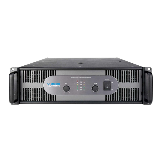
V-8000
CH 1
CH 2
OFF
-5dB
-10dB
-20dB
SIGNAL
POWER
POWER
0
10
0
10
PROFESSIONAL POWER AMPLIFIER
PROTECT
CH 1
CLIP
CH 2
V-9000
OFF
-5dB
-10dB
-20dB
SIGNAL
POWER
POWER
0
10
0
10
Index
02 Introduction
03 Front Panel
04 Rear Panel
0
6 Set Up
08 Speakon Assembly
09 Operating Modes
11 Protection
12 Features
13 Specifications
User Instructions
This booklet contains important information concerning the proper and safe operation of your new amplifier..
V-Series
V-8000 / V-9000
Made in Taiwan
Advertisement
Table of Contents

Related Manuals for Unika V-Series


Summary of Contents for Unika V-Series
- Page 1 -20dB SIGNAL POWER POWER User Instructions This booklet contains important information concerning the proper and safe operation of your new amplifier.. Index V-Series V-8000 / V-9000 Made in Taiwan 02 Introduction 03 Front Panel 04 Rear Panel 6 Set Up...
- Page 2 IMPORTANT SAFETY INSTRUCTIONS V-8000/V-9000 This symbol is intended to alert the user to the presence of This symbol is intended to alert the user of non insulated "dangerous voltage" within the product's the presence of important operating and CAUTION enclosure that may be of sufficient magnitude to constitute maintenance (servicing) instructions in the Do not open - a risk of electric shock to persons.
-
Page 3: Important Precautions
Congratulations and thank you for purchasing V-8000/V-9000 amplifier. moisture. These amplifiers are representation of UNiKA’s continuing commitment to Do not spill water or other liquids into or on to your unit. produce the best and highest quality audio products at an affordable price. -
Page 4: Front Panel
8. Power Indicator – This LED will glow when mains power is applied to the unit. 3. UNiKA Logo and Model No - V series have 2 types of 3U Models V-8000/V- This light may continue to glow briefly after mains power has been turned off 9000. -
Page 5: Rear Panel
UNiKA V-8000/V-9000 Rear Panel Introduction Front Panel Set Up Speakon Assembly Operating Modes Protection Features Specifications V-8000 REAR PANEL LIMITER PINOUT CH 1 PUSH SENSITIVITY POS NEG CH 2 POS NEG 0.775V 1.44V BRIDGE MODE POS NEG STEREO PARALLEL BRIDGE... - Page 6 UNiKA V-8000/V-9000 Rear Panel Introduction Front Panel Set Up Speakon Assembly Operating Modes Protection Features Specifications V-9000 REAR PANEL LIMITER PINOUT CH 1 PUSH SENSITIVITY POS NEG CH 2 0.775V 1.44V POS NEG BRIDGE MODE STEREO PARALLEL BRIDGE POS NEG...
- Page 7 UNiKA V-8000/V-9000 Set Up Introduction Front Panel Rear Panel Speakon Assembly Operating Modes Protection Features Specifications SET UP Male XLR Pin Configuration INPUTS - The V-8000/V-9000 amplifier allows you to use XLR female jack for balanced connection per channel. Use this connection to connect the output signal from a mixer, cross-over or EQ to your amplifiers.
- Page 8 UNiKA V-8000/V-9000 Set Up Introduction Front Panel Rear Panel Speakon Assembly Operating Modes Protection Features Specifications SPADE CONNECTOR: (Figure 7) When connecting your speakers to the amplifier using spade connector, unscrew the red and black caps on the binding post, be sure not to completely remove or unscrew the red and black caps. Insert the spade connector into the binding post and tighten the caps down on the spade connector.
-
Page 9: Speakon Assembly
UNiKA V-8000/V-9000 Speakon Assembly Introduction Front Panel Rear Panel Set Up Operating Modes Protection Features Specifications SPEAKON ASSEMBLY: You will need a pair of Neutrik Speakon NL4FC connectors. You will also need high-quality two or four conductor Speakon cable, a pair of needle-nosed pliers and a 1.5-mm Allen key... -
Page 10: Operating Modes
UNiKA V-8000/V-9000 Operating Modes Introduction Front Panel Rear Panel Set Up Speakon Assembly Protection Features Specifications OPERATING MODES STEREO OPERATION : Page 9/ Figure 14 details an example of a typical stereo set-up. Connect your inputs into channels one and two of the amplifier. - Page 11 UNiKA V-8000/V-9000 Operating Modes Introduction Front Panel Rear Panel Set Up Speakon Assembly Protection Features Specifications CH-1 Input Only MODE STEREO PARALLEL BRIDGE V-9000 Rear Panel LIMITER PINOUT CH 1 PUSH POS NEG SENSITIVITY CH 2 0.775V 1.44V POS NEG...
-
Page 12: Short Circuit Protection
UNiKA V-8000/V-9000 Protection Introduction Front Panel Rear Panel Set Up Speakon Assembly Operating Modes Features Specifications PROTECTION LIMITER - -8000/V-9000 amplifiers comes with a built in limiter. When the input signal overloads, the “CLIP LED” indicates a signal overload, at this time, the volume should be lowered to reduce distortion. -
Page 13: Amplifier Features
UNiKA V-8000/V-9000 Protection Features Introduction Front Panel Rear Panel Set Up Speakon Assembly Operating Modes Specifications INPUT/OUTPUT PROTECTION - The input circuits are isolated by resistors. An ultrasonic network uncouples RF from the output and helps to keep the amplifier stable with reactive loads. -
Page 14: V-Series Amplifier Specifications
UNiKA V-8000/V-9000 Specifications Introduction Front Panel Rear Panel Set Up Speakon Assembly Operating Modes Protection Features V-SERIES AMPLIFIER SPECIFICATIONS MODEL NO. V-8000 V-9000 Output Power: 1300W RMS Stereo. 1700W RMS Stereo. 2 ohms,1KHz 1% THD 1850W RMS Stereo. 2150W RMS Stereo. - Page 15 UNiKA V-8000/V-9000 Specifications Introduction Front Panel Rear Panel Set Up Speakon Assembly Operating Modes Protection Features page 14...
- Page 16 UNiK A Professional Power Amplif iers...
Need help?
Do you have a question about the V-Series and is the answer not in the manual?
Questions and answers