
Related Manuals for Maico ER-UP/GH


Summary of Contents for Maico ER-UP/GH
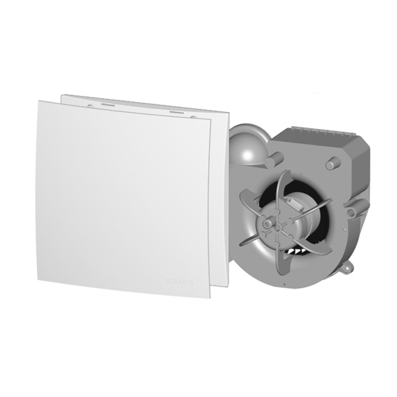
- Page 1 Mounting and operating instructions Recess-mounted exhaust air system according to DIN 18017-3 ER-UP/GH ER 60 E ER 100 E w w w . m a i c o - v e n t i l a t o r e n . c o m...
-
Page 3: Table Of Contents
11. Mounting preparations ........13 Fan insert 11.1 Installation specifications for Electronic circuit boards ER-UP/GH with ER 60 E or ER 100 E Housing floor seal single room/second room ......13 Sensor (H model) 11.2 Preparations for wall installation ..14 Cover 11.3 Ceiling installation preparations .. -
Page 4: Fan Insert
Scope of delivery Depending on order, comprising: Second room connection set ER-ZR article no. 0093.1025 ● Shell kit = ER-UP/GH recess-mounted ● Comprising protective grille, filter mat housing + exhaust socket and plastic adapter, plastic exhaust socket and shutter, complete. -
Page 5: General Notes
1. General notes 1. General notes 4. Non-intended use Please read these instructions These fans must not be used in the following carefully. Follow the instructions. situations under any circumstances. Read Pass these instructions onto the all the safety instructions. owner. -
Page 6: Safety Instructions
4. Non-intended use 5. Safety instructions NOTICE: Damage to the unit ● During the build phase, damage to unit WARNING caused by soiling of the fan and air channels. Risks for children and people Fan operation is not permitted during the build phase. - Page 7 5. Safety instructions WARNING DANGER Risk of injury when working at heights. Risks from parts which may affect the Use appropriate, certified climbing aids ventilation system which are added or modified at a later date. Parts (range (ladders). Stability should be ensured, if necessary have the ladders steadied by hood, air-ventilated fireplace etc.) which a 2nd person.
- Page 8 5. Safety instructions DANGER DANGER of fire spreading Danger of electric shock. Before In the event of a fire, there is a risk removing the housing cover and before of the fire spreading installing the electrics, switch off all supply ●...
-
Page 9: Operating The Fan
Alternatively, these units can be for these fan inserts. operated using an optional switch. The connection diameter for ER-UP/GH Please read chapter 7.3.3 (ER-UP controls) housings is Ø 75 or Ø 80. or contact your installer or planner for details of the special functions and operating 7.1 Installation conditions... -
Page 10: Permitted Exhaust Air Systems
Yes* without fire protection installation: upwards, to right or to left. ● Plastic exhaust socket with airstream-ope- ER-UP/GH can be used inside and outside rated plastic shutter, maintenance-free. the shaft, connection duct made from ● For connecting second room ventilation... - Page 11 7. Product information ● Energy-saving motor with thermal overload 7.3.3 ER-UP controls (circuit board types) protection. This switches itself off in the ER-UP fans are available in various models event of overheating and then back on and with various unit properties. These again automatically after cooling down.
-
Page 12: Environmental Conditions And Operating Limits
Ambient temperature - 10 °C ensured during operation with air-ventilated to + 60 °C. fireplaces. The maximum permitted pressure Maico accepts no liability for corrosion difference per living unit is 4 Pa. damage caused by improper storage, e.g. storage in damp surroundings. -
Page 13: Mounting Preparations
11. Mounting preparations Suitable mounting material is to be supplied by the customer. 11.1 Installation specifications for ER-UP/GH with ER 60 E or ER 100 E single room/second room Number of units per floor, living unit Max. 3 fans or 3 connections... -
Page 14: Preparations For Wall Installation
1. Produce opening in shaft or alternatively 15 Suction duct for second room connection produce a wall facing. Ensure a suitable, on ER-UP/GH: flexible aluminium duct flat surface for the ER-UP housing so that AFR 75/AFR 80 the fan insert can be safely inserted in the 18 Main duct: Steel folded spiral-seams duct housing later on. -
Page 15: Ceiling Installation Preparations
Suction duct for second room connection exhaust socket and also sealed for on ER-UP/GH: flexible aluminium duct ventilation at the unit end. AFR 75/AFR 80 7. Lay suction duct [15] and seal gap... - Page 16 11. Mounting preparations Main duct (steel folded spiral-seams Duct attachment with duct clamp, alterna- duct) tively duct attachment with clamping band Connection duct ER-UP/GH: Flexible aluminium duct Floor ceiling Steel threaded rod / stair bolt Duct attachment Fig. 5...
-
Page 17: Preparations For The Electrical Connection
11.5 Preparing the shutter 7. Connect permitted connection duct [19] 11.5.1 Plastic shutter without fire to main duct and seal for ventilation, for protection ‒ ER-UP/GH housing example with cold-shrink tape. 8. Apply wall/board compound [27]. Seal gap NOTICE between brickwork and folded spiral- seams duct. -
Page 18: Housing Installation
3. Insert shutter [2] into exhaust socket as correctly in the ER-UP/GH housing and the shown in Fig. 6 until it reaches the stop. degree of protection stated on the rating plate Check position and ensure function. - Page 19 Exhaust socket with plastic shutter required length, bend it into shape and 18 Main duct, steel folded spiral-seams duct fix it to the ER-UP/GH housing with the 19 Connection duct, flexible aluminium duct supplied fixing screws. AFR 80 Ø 75/ Ø 80 20 Power cable 3.
- Page 20 2. For suspended ceilings, cut mounting support [37] to the required length, bend it 9. Plaster in housing flush with front edge. into shape and fix it to the ER-UP/GH housing with the supplied fixing screws ( Fig. 7). 3. Mark fixing holes for mounting support and/or ER-UP/GH housing on ceiling, produce holes and insert dowels.
- Page 21 12. Installation ‒ ER-UP/GH ‒ second room Housing floor seal 2. Place installation socket [11] in ER-UP/GH housing. The edge of the socket must click Installation socket for second room into place on the wall of the housing. extraction Ø 75 / Ø 80 Adapter 3.
- Page 22 12. Installation ‒ ER-UP/GH ‒ second room Installation socket for second room 12.1.7 Ceiling installation ER-UP/GH ‒ extraction Ø 75 / Ø 80 second room Adapter Observe mounting information in chapter Filter mat, filter class G2 12.1.2. Protective grille 1. Mount ER-UP/GH housing on ceiling as Suction duct, second room connection: described in chapter 12.1.5.
-
Page 23: Electrical Connection
13. Electrical connection 13. Electrical connection DANGER Danger to life from electric shock/The 20 Power cable unit will be damaged if installed 39 Cable grommet incorrectly with too long a power cable. 41 Terminal box If the cable feed is too long inside the housing, the fan insert cannot be in- To prevent the fan and/or electric stalled correctly. - Page 24 13. Electrical connection 13.1.1 Connect the unit electrically NOTICE 1. Switch off mains fuse, secure and fit Unit damage caused by EVZ and EH warning sign. units touching ESD sensitive components on the electronic circuit 2. Remove plaster protective cover. board.
-
Page 25: Installation Of Fan Insert And Cover
14. Installation of fan insert and cover If there are no further increases, the unit 14. Installation of fan insert and continues to run at nominal load level 1 until cover the humidity again falls below the saved reference value. 14.1 Settings on electronic circuit If the humidity falls below the saved reference boards... - Page 26 14. Installation of fan insert and cover Fan insert Note wiring diagrams in box base. Electronic circuit board (control) Cables must not prevent the fan from Housing floor seal being slid in. 38 Plaster protective cover Lever [43] and stud 41 Terminal box [44] 42 Optional fixing with screws...
-
Page 27: Installing The Cover
4. Switch off unit. vide compensation if housing is inserted at too much of an angle). If installing on a wall, ensure that the Maico name is in the bottom right. ● If the housing edge is flush with the plas- ter, use central screw [7.1], M6 x 16 mm,... -
Page 28: Cleaning, Maintenance
10 Filter mat, filter class G2 1. Only use a dry cloth to clean the cover [7] In case of questions, please contact: of the fan. Maico Elektroapparate-Fabrik GmbH 2. If the cover is very dirty, remove it and Steinbeisstraße 20 clean with water. -
Page 29: Filter Change, Second Room
Degree of protection according to Filter-Shop: rating plate only guaranteed if www.ventilatorshop24.com installed as stipulated (fan insert engaged, internal cover closed). In case of questions, please contact: Maico Elektroapparate-Fabrik GmbH Steinbeisstraße 20 78056 Villingen-Schwenningen Germany Tel. +49 7720 694 445 +49 7720 694 175 Internet: www.ventilatorshop24.com... -
Page 30: Extraction Socket Er-As For Wc Odour Extraction
17. Extraction socket ER-AS for WC odour extraction ER-UP/GH housing units can be connected 17. Extraction socket ER-AS for to the WC flushing pipe using the ER-AS WC odour extraction extraction socket. A Ø 70 duct cross section facilitates low air speeds in the connecting duct and an effective, draft-free extraction of odours. -
Page 31: Fault Rectification
18. Fault rectification 18. Fault rectification Fault Cause, measure Fan is too loud. ● Dirty filter. ● Call on the services of a trained electrician Replace filter. any time there is a fault. ● Fan insert incorrectly ● Repairs should only be carried out by a installed. -
Page 32: Spare Parts
G2 according to you are. EN 779 Dispose of the air filter in an Maico Elektroapparate-Fabrik GmbH environmentally-friendly way, in compliance Steinbeisstraße 20 with the regulations valid in the country where 78056 Villingen-Schwenningen you are. -
Page 33: Wiring Diagrams
22. Wiring diagrams 22. Wiring diagrams Tolerances for the times stated below = nominal value + 20 %. ER 60 E, ER 100 E ER 60 E and ER 100 E The fan starts up after switching on the room lighting (with switch S1). - Page 34 22. Wiring diagrams ER 60 EH, ER 100 EH ER 60 EH, ER 100 EH Standard switching: For function of the humidity control chapter 14.1. The humidity variant must not be deactivated using a switch on terminal 1 and/or terminal N. Standard switching: Permanent base load operation The fan is running in base load operation,...
- Page 35 22. Wiring diagrams ER 60 EH, Switching option 2: Manual base load operation ER 100 EH The fan is switched manually to base load Switching option 2 operation with switch "S1". Humidity control is active, see Standard Switching. If, after being manually switched with switch "S1", the fan is in: ●...
- Page 36 Maico Elektroapparate-Fabrik GmbH • Steinbeisstr. 20 • 78056 Villingen-Schwenningen • Germany • Service +49 7720 6940 • technik@maico.de...
Need help?
Do you have a question about the ER-UP/GH and is the answer not in the manual?
Questions and answers