Table of Contents
Advertisement
P O W E R I N G
T E C H N O L O G Y
OPERATING MANUAL
BLUESTREAK SERIES
FRONT-ENDS & RECTIFIERS
© 2019 UNIPOWER LLC
Document Number: BLUESTREAK-MAN Rev. 6
All Rights Reserved
UNIPOWER, LLC
65 Industrial Park Rd
Dunlap, TN 37327
Phone: +1-954-346-2442
Toll Free: 1-800-440-3504
Web site:
www.unipowerco.com
Advertisement
Table of Contents

Related Manuals for Unipower Bluestrak Series


Summary of Contents for Unipower Bluestrak Series
- Page 1 P O W E R I N G T E C H N O L O G Y OPERATING MANUAL BLUESTREAK SERIES FRONT-ENDS & RECTIFIERS © 2019 UNIPOWER LLC Document Number: BLUESTREAK-MAN Rev. 6 All Rights Reserved UNIPOWER, LLC 65 Industrial Park Rd...
-
Page 2: Table Of Contents
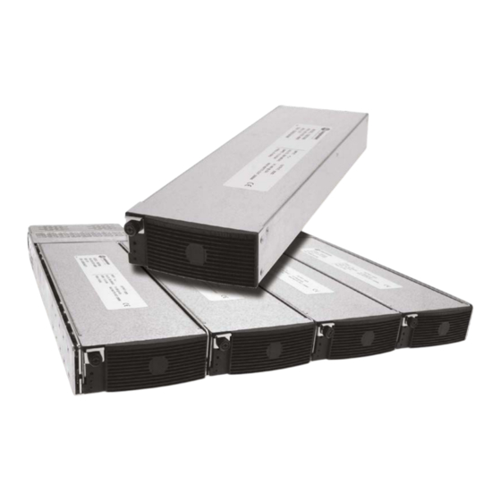
BLUESTREAK SERIES P O W E R I N G T E C H N O L O G Y INSTALLATION & OPERATING MANUAL DESCRIPTION CHK’d & APPR’d / DATE PCO# 45394 MM / 07-31-19 Contents INTRODUCTION .......................4 STANDARD FEATURES ....................5 SUMMARY OF PRODUCT LINE ..................5 SAFETY WARNINGS......................6 WARRANTY (summary) ....................6... - Page 3 BLUESTREAK SERIES P O W E R I N G T E C H N O L O G Y INSTALLATION & OPERATING MANUAL FIGURES Figure 1 - BLUEstreak Module & Power Shelf ................4 Figure 2 - Front Panel Detail ......................7 Figure 3 - Possible LED Combinations ...................8 Figure 4 - Timing Diagram ......................13 Figure 5 - Module Dimensions ......................14...
-
Page 4: Introduction
BLUESTREAK SERIES P O W E R I N G T E C H N O L O G Y INSTALLATION & OPERATING MANUAL OPERATING MANUAL BLUESTREAK SERIES FRONT-ENDS & RECTIFIERS INTRODUCTION This Operating Manual should be read through carefully before installing and operating the BLUEstreak Series Front-Ends and Rectifiers. -
Page 5: Standard Features
BLUESTREAK SERIES P O W E R I N G T E C H N O L O G Y INSTALLATION & OPERATING MANUAL STANDARD FEATURES Up to 92% Efficiency Power Density to 24W/Cu. Inch 1U High: 1.6” ... -
Page 6: Safety Warnings
God, negligence or the failure of customer to fully follow instructions with respect to installation, application or maintenance. For a complete text of UNIPOWER’s warranty conditions please request a copy from your local Sales Office. -
Page 7: Module Specifications
BLUESTREAK SERIES P O W E R I N G T E C H N O L O G Y INSTALLATION & OPERATING MANUAL MODULE SPECIFICATIONS The following specifications are typical at 25°C unless otherwise noted. INPUT STATUS INDICATORS Voltage Range ..............See Model Table STATUS .................. -
Page 8: Figure 3 - Possible Led Combinations
BLUESTREAK SERIES P O W E R I N G T E C H N O L O G Y INSTALLATION & OPERATING MANUAL PUSH BUTTONS The two push buttons located just above the LEDs can be used to adjust the output voltage when the output is enabled. -
Page 9: Description Of Operation
BLUESTREAK SERIES P O W E R I N G T E C H N O L O G Y INSTALLATION & OPERATING MANUAL DESCRIPTION OF OPERATION Power Outputs The power output terminals provide the main output power of the unit. The output voltage is adjustable by means of the front panel recessed push buttons or by programming with the PMBus or by using the analogue remote adjust pin. - Page 10 BLUESTREAK SERIES P O W E R I N G T E C H N O L O G Y INSTALLATION & OPERATING MANUAL Remote Adjust Output Voltage Voltage 48VDC 24VDC 12VDC 24.0 11.82 29.0 14.35 7.25 34.2 16.84 39.4 19.35 9.75 44.2...
- Page 11 BLUESTREAK SERIES P O W E R I N G T E C H N O L O G Y INSTALLATION & OPERATING MANUAL 9.2.10 #FANOK This signal provides an open drain output that indicates that the fans speeds are more than 80% of the required speed.
- Page 12 BLUESTREAK SERIES P O W E R I N G T E C H N O L O G Y INSTALLATION & OPERATING MANUAL 9.2.16 GA0, GA1, GA2, GA3, GA6 These are the PMBus interface address lines. They are used to set the hardware address of each module on the backplane.
-
Page 13: Figure 4 - Timing Diagram
BLUESTREAK SERIES P O W E R I N G T E C H N O L O G Y INSTALLATION & OPERATING MANUAL ACV Input AC ON AC ON DC Main Output ON-RISE VOUT-HOLDUP ACOK ACOK-RISE ACOK-FALL ACOK-OFF ACOK-ON DCOK-RISE DCOK DCOK-FALL... -
Page 14: Mechanical Specifications
BLUESTREAK SERIES P O W E R I N G T E C H N O L O G Y INSTALLATION & OPERATING MANUAL 10.0 MECHANICAL SPECIFICATIONS The mechanical dimensions of the BLUEstreak module are shown. Note that BLUEstreak modules are designed for hot-swap applications only and are not provided with any fixing points. -
Page 15: Safety And Industry Standards
BLUESTREAK SERIES P O W E R I N G T E C H N O L O G Y INSTALLATION & OPERATING MANUAL 11.0 SAFETY AND INDUSTRY STANDARDS BLUEstreak modules and power shelves meet the following safety standards: 11.1 UL60950-1, 2nd Edition CSA22.2 No. -
Page 16: Figure 7 - Mating Interface Board
BLUESTREAK SERIES P O W E R I N G T E C H N O L O G Y INSTALLATION & OPERATING MANUAL SIGNAL PIN CONNECTIONS FUNCTION FUNCTION #MODULE PRESENT Sense +Ve Current Monitor Standby Return 5V Standby 1, 3 #FANOK #DCOK #SMBALERT... - Page 17 BLUESTREAK SERIES P O W E R I N G T E C H N O L O G Y INSTALLATION & OPERATING MANUAL Output Voltage - The output voltage is factory set to its nominal value to an accuracy of 12.4 ±1%.
- Page 18 BLUESTREAK SERIES P O W E R I N G T E C H N O L O G Y INSTALLATION & OPERATING MANUAL 12.6 Overvoltage Protection - The power supply has two internal O.V.P. protection circuits. One operates at a fixed voltage level and the other is programmable by the PMBus. The fixed O.V.P.
-
Page 19: Parallel Operation
BLUESTREAK SERIES P O W E R I N G T E C H N O L O G Y INSTALLATION & OPERATING MANUAL 13.0 PARALLEL OPERATION 13.1 Parallel Connection - Two or more BLUEstreak modules can be operated in parallel by connecting their outputs in parallel and connecting their current sense terminals together (pin D2). -
Page 20: Module Installation
BLUESTREAK SERIES P O W E R I N G T E C H N O L O G Y INSTALLATION & OPERATING MANUAL 14.0 MODULE INSTALLATION BLUEstreak Series modules are designed for mounting into the BLUEstreak Series power shelves or similar OEM housing. -
Page 21: Compatible 19-Inch Power Shelves
BLUESTREAK SERIES P O W E R I N G T E C H N O L O G Y INSTALLATION & OPERATING MANUAL 15.0 COMPATIBLE 19-INCH POWER SHELVES There are four 19-inch compatible power shelves with single and dual bus configurations being available. - Page 22 BLUESTREAK SERIES P O W E R I N G T E C H N O L O G Y INSTALLATION & OPERATING MANUAL The DC output is supplied on two pairs of internally connected bus bars with four 1/4-20 threaded bolts for each bar spaced 0.625”...
-
Page 23: Figure 10A - Model Tbsr1Uc With Iec Connectors
BLUESTREAK SERIES P O W E R I N G T E C H N O L O G Y INSTALLATION & OPERATING MANUAL SIGNAL CONNECTOR - J3 PIN FUNCTION PIN FUNCTION J3 - Spring Clamp Sense +Ve Sense +Ve Sense -Ve Sense -Ve Current Share... - Page 24 BLUESTREAK SERIES P O W E R I N G T E C H N O L O G Y INSTALLATION & OPERATING MANUAL The DC output is supplied on two pairs of bus bars with four 1/4-20 threaded bolts for each bar spaced 0.625”...
- Page 25 BLUESTREAK SERIES P O W E R I N G T E C H N O L O G Y INSTALLATION & OPERATING MANUAL SIGNAL CONNECTORS - J2A & J2B FUNCTION FUNCTION J2A & J2B - RJ45 #SMBALERT - A #SMBALERT - B SDA - A SDA - B...
-
Page 26: Mechanical Dimensions
BLUESTREAK SERIES P O W E R I N G T E C H N O L O G Y INSTALLATION & OPERATING MANUAL 16.0 MECHANICAL DIMENSIONS Figure 11 below shows outline dimensions for the BLUEstreak Series Power Shelves. 18.62 (473) 16.57 (420,8) -
Page 27: Shelf Installation
Dual bus shelves will allow for a true A+B supply to equipment requiring such a facility. The four 1/4-20 threaded bolts on each bar are spaced 0.625” apart. UNIPOWER can supply various pre-made DC load cables; see the current datasheet for available options. -
Page 28: Figure 13 - Dc Bus Bar Terminal Detail
OUTPUT B connected together to create higher capacity power systems than can be achieved with a single shelf. UNIPOWER offers bus bar linking kits as follows: 2 shelf kit, part number 775-1509-0020. Contains two short link bars, one for connecting the two positive bus bars together and one for connecting the two negative bus bars together. -
Page 29: Maintenance
3 inches (76mm) free space behind and in front of the power shelf when it is installed in the rack. UNIPOWER also recommends that any equipment mounted directly above the BLUEstreak power shelf should be shorter in overall depth so as to not obstruct any ventilation holes in the top surface. -
Page 30: Setup And Testing
BLUESTREAK SERIES P O W E R I N G T E C H N O L O G Y INSTALLATION & OPERATING MANUAL 19.0 SETUP AND TESTING 19.1 The BLUEstreak can be initially tested mounted in a rack or on a test bench. If two or more units are to be tested in a rack, they should first be individually tested in Position 1 (left side) of the rack. - Page 31 BLUESTREAK SERIES P O W E R I N G T E C H N O L O G Y INSTALLATION & OPERATING MANUAL 19.9 Testing other BLUEstreak modules - For a power shelf with two, three or four BLUEstreak modules, the other modules should be plugged into Position 1 in the rack and tested in the same manner as above in Sections 19.2 to 19.8.
-
Page 32: Pmbus Demonstration Program
Figure 14 - PMBus Demonstration Program Screen Shot To use this program a PC to I²C Adaptor is required and UNIPOWER recommends and can supply the I2C2PC Adaptor detailed at www.i2cchip.com/pdfs/i2c2pc.pdf. This adaptor provides both RS232 and USB connections to the host PC and requires an external 9-12VDC power supply when the RS232 interface is utilised. - Page 33 BLUESTREAK SERIES P O W E R I N G T E C H N O L O G Y INSTALLATION & OPERATING MANUAL free operation. To run the program, it is necessary create a shortcut on the windows desktop and then add the required com port outside the quote marks in the target box (shortcut properties).
-
Page 34: Figure 15 - Pmbus Command Summary
BLUESTREAK SERIES P O W E R I N G T E C H N O L O G Y INSTALLATION & OPERATING MANUAL CODE NAME SHORT DESCRIPTION CODE NAME SHORT DESCRIPTION Used for on/off and margining OPERATION STATUS_BYTE Reads the status byte Used to configure the function of ON_OFF_CONFIG STATUS_WORD... -
Page 35: Troubleshooting Guide
What actions have been taken since the problem occurred? This document is believed to be correct at time of publication and UNIPOWER LLC accepts no responsibility for consequences from printing errors or inaccuracies. Specifications are subject to change without notice.
Need help?
Do you have a question about the Bluestrak Series and is the answer not in the manual?
Questions and answers