Table of Contents
Advertisement
P O W E R I N G
T E C H N O L O G Y
Power Supply System
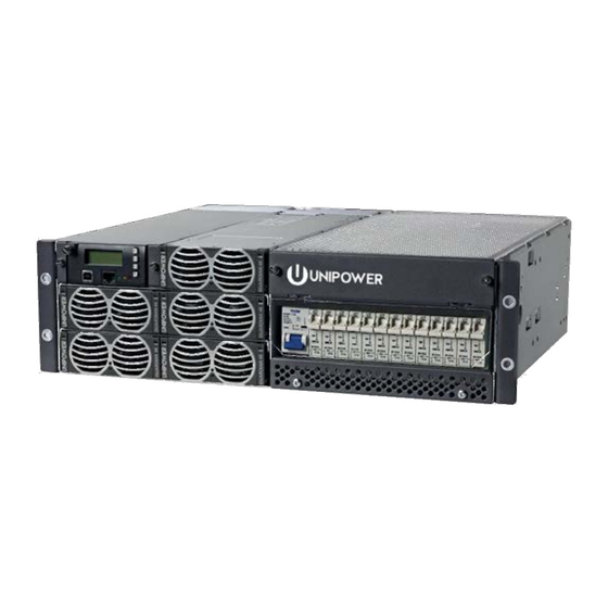
Guardian Access 3U
Instruction Manual
www.unipowerco.com
© 2017 UNIPOWER LLC
Document Number: MS0027-MAN rev. 4
All Rights Reserved
guardian_access_3u_ms27-man-rev4-0817.indd
UNIPOWER LLC • 3900 Coral Ridge Drive, Coral Springs, Florida 33065, USA • sales@unipowerco.com
North America: +1 954-346-2442 • Europe: +44 1903 768200
Advertisement
Table of Contents
Troubleshooting

Related Manuals for Unipower Guardian Access 3U


Summary of Contents for Unipower Guardian Access 3U
- Page 1 Guardian Access 3U Instruction Manual www.unipowerco.com © 2017 UNIPOWER LLC Document Number: MS0027-MAN rev. 4 All Rights Reserved guardian_access_3u_ms27-man-rev4-0817.indd UNIPOWER LLC • 3900 Coral Ridge Drive, Coral Springs, Florida 33065, USA • sales@unipowerco.com North America: +1 954-346-2442 • Europe: +44 1903 768200...
- Page 2 UNIPOWER LLC, which consent may be withheld by UNIPOWER LLC in its sole discretion. Users assume all risk and liability for, and agree to indemnify and defend UNIPOWER from and against any claims for personal injury (including death) or property damage resulting from any such use or application which is made in the absence of such prior express written consent.
-
Page 3: Table Of Contents
P O W E R I N G T E C H N O L O G Y Contents Chapter 1 About This Manual ......................6 1.1 Objectives ..........................6 1.2 Audience ............................6 1.3 Document Key ...........................6 1.4 Feedback & Support ........................7 1.5 Disclaimer ..........................7 Chapter 2 System Description ......................8 2.1 Overview ............................8... - Page 4 P O W E R I N G T E C H N O L O G Y 4.3 Cable Entry ..........................26 4.3.1 Remove Top Cover ......................26 4.3.2 Cable Entry Openings .....................27 4.5 AC Input Connection .......................29 4.6 DC Load Connection .......................31 4.7 Battery Connection ........................32 4.8 Alarm and Signal Connections ....................32 4.9 Symmetry Connection ......................35...
- Page 5 P O W E R I N G T E C H N O L O G Y FIGURES Figure 2-1 Power System Overview .....................8 Figure 2-2 Principal of Operation ....................9 Figure 2-3 Power System With Extension Rear and Top Cover Kit ..........10 Figure 2-4 Power System with Rear and Top Cover Kit ............10 Figure 2-5...
-
Page 6: Chapter 1 About This Manual
Chapter 1 About This Manual P O W E R I N G T E C H N O L O G Y 1. About This Manual This chapter contains an overview of the information that is presented in this Power System Manual. -
Page 7: Feedback & Support
For technical support or feedback, please visit http://www.unipowerco.com/contact/. Alternatively, email: technical.support.repair@unipowerco.com 1.5 Disclaimer UNIPOWER is not responsible for system problems that are the result of installation or modification of the instructions provided in this manual. Manual No. MS0027-MAN rev. 4 guardian_access_3u_ms27-man-rev4-0817.indd... -
Page 8: Chapter 2 System Description
This chapter contains an overview of the system and a short description of the units in the system. The Guardian Access 3U power system is designed to meet the requirements of modern telecommunications equipment. This power solution provides rectification, system management and power distribution. -
Page 9: Figure 2-2 Principal Of Operation
T E C H N O L O G Y The Guardian Access 3U is capable of delivering up to 14.7kW steady state power to the combined load and batteries. The maximum power available to the load is 10.7kW. The system is based on hot-swappable 48V rectifier modules which are working in parallel with automatic load sharing. -
Page 10: Figure 2-3 Power System With Extension Rear And Top Cover Kit
P O W E R I N G T E C H N O L O G Y To meet the requirements of different application, there are two kinds of Rear and Top Cover Kit available: • Rear and Top Cover Kit for cabinets •... -
Page 11: System Parameters
P O W E R I N G T E C H N O L O G Y 2.2 System Parameters OUTPUT Power (max) 10.7kW load + 4kW battery charge @ 230/400VAC nominal 9.4kW load + 4kW battery charge @ 120VAC nominal Output Current (max) 200A load + 75A battery charge @ 230/400VAC nominal 175A load + 75A battery charge @ 120VAC nominal... - Page 12 P O W E R I N G T E C H N O L O G Y MECHANICAL Dimensions (WxHxD) 19” (483mm) x 5.2” (133mm) x 16.1” (408mm) std cover | 19.1” (485)mm ext. cover Weight of the system 67lbs (30.5kg) (fully equipped) Mounting Options...
-
Page 13: System Components
2.3 System Components With the exception of the rectifier modules the Guardian Access 3U system is delivered with all components mounted according to the ordered configuration. The main components are described below and in later chapters of this manual. -
Page 14: Rectifier Module
P O W E R I N G T E C H N O L O G Y 2.3.2.1 Low Voltage Disconnect (LVD) and Dummy LVD Generally, the system is equipped with low voltage battery disconnection, which prevents the batteries from deep discharging, thus prolonging the battery life. A disconnection requires a detected mains failure at the supervision unit. -
Page 15: Chapter 3 System Safety
Chapter 3 System Safety P O W E R I N G T E C H N O L O G Y 3.1 Safety Warnings and Guidelines The following warnings and guidelines should be followed by properly trained and authorized personnel when installing, operating, commissioning or maintaining this equipment. -
Page 16: Installation Warning
NOTE This may be disregarded for systems delivered in a UNIPOWER Outdoor enclosure. 3.1.5 System Enclosure Appropriate measures need to be taken to avoid intrusion of any unwanted objects or insects into conductive areas of the power system as there is a potential risk of system damage. -
Page 17: Electrical Safety Warnings
P O W E R I N G T E C H N O L O G Y 3.1.7 Electrical Safety Warnings The following are electrical safety recommendations for working near the Power System: WARNING Observe low voltage safety precautions before attempting to work on the system when power is connected. -
Page 18: Grounding
P O W E R I N G T E C H N O L O G Y 3.1.8 Grounding WARNING Grounding connection must be performed before operating the system. Refer to local codes, e.g. ANSI, CEC, NEC, T1-333, ETSI 300-386-TC specifying the connection of power system to building ground. -
Page 19: In Case Of An Accident
P O W E R I N G T E C H N O L O G Y 3.1.10 In Case of an Accident In the event of an accident resulting in injury: 1. Use caution and check for hazards in the area. 2. -
Page 20: Breakers
P O W E R I N G T E C H N O L O G Y 3.2.5 Breakers Maximum 45°C operating ambient: 1. UP to 32A CB maximum load must not exceed 80% of it’s rating. 2. 40A CB maximum load shall not exceed 30A. 3. -
Page 21: Chapter 4 Installation Guide
Chapter 4 Installation Guide P O W E R I N G T E C H N O L O G Y 4.1 Preparation 4.1.1 Installation Overview The following is the recommended sequence for the installation procedures. The sequence may change according to job or actual configuration. •... -
Page 22: Tools
P O W E R I N G T E C H N O L O G Y 4.1.3 Tools The following tools are required for a safe installation of the system: • Anti-static hand strap. • Socket wrench, insulated. •... -
Page 23: Cable Size
P O W E R I N G T E C H N O L O G Y 4.1.4 Cable Size Please use the recommended cable size given below for the system installation. Port Current Cable Size Cable Size Temperature Max. -
Page 24: Rack Mounting
P O W E R I N G T E C H N O L O G Y 4.2 Rack Mounting There are two mounting brackets installed on the front left and right side of the power system to enable you to securely fasten the sub-rack to a cabinet or an open frame. NOTE For ease of mounting the power rack it is recommended to remove the rectifiers. -
Page 25: Figure 4-2 System Mounting - Open Frame / Relay Rack
P O W E R I N G T E C H N O L O G Y To mount the system into an open frame, follow the steps below: 1. Determine the installation position according to system measurement. Refer to the Appendix A for details. -
Page 26: Cable Entry
P O W E R I N G T E C H N O L O G Y 4.3 Cable Entry If the Rear and Top Cover Kit or Extended Rear and Top Cover Kit is installed on the power system, the top cover should be removed for connecting AC, DC, alarm and temperature sensor cables. -
Page 27: Cable Entry Openings
P O W E R I N G T E C H N O L O G Y Top Cover Front Panel AC Input Cover Figure 4-4 Remove Top and AC Input Cover 4.3.2 Cable Entry Openings The Extended Rear and Top Cover is designed with two knockouts and one circular opening for AC cable entry plus and three larger openings for DC and alarm cable entry. -
Page 28: Figure 4-6 Grounding Connection
P O W E R I N G T E C H N O L O G Y 4.4 Grounding Connection Earth grounding connection is essential before connecting to the AC supply. The positive DC busbar is connected to the grounding point in the rear of the system using a copper bar. -
Page 29: Ac Input Connection
P O W E R I N G T E C H N O L O G Y Figure 4-8 Grounding Connection with Extended Rear Cover - Single Point 4.5 AC Input Connection WARNING Ensure that mains input is turned off before connecting. The grounding must be connected to PE terminal as first. -
Page 30: Figure 4-9 Ac Input Terminal Block (1-Phase)
P O W E R I N G T E C H N O L O G Y LI L2 L3 NI N2 N3 PE PE 2.0 Nm + 10% Figure 4-9 AC Input Terminal Block (1-phase) Recommended mains breaker: 100-120VAC 1W+N+PE or 208-240VAC 1W+N+PE or 200-240VAC 2W+PE: UL listed, Single pole 3 x 50A C-characteristics. -
Page 31: Dc Load Connection
P O W E R I N G T E C H N O L O G Y 4.6 DC Load Connection Before connecting DC load cables, check that the cable rating is matched with selected the MCB and/or load. 1. -
Page 32: Battery Connection
P O W E R I N G T E C H N O L O G Y 4.7 Battery Connection The battery cables are not delivered with the system. 1. Check that all the battery MCBs are in the OFF position. 2. -
Page 33: Figure 4-13 Pcc External Board
P O W E R I N G T E C H N O L O G Y External Alarm Interface (BM0723) -12V J1 Multi-purpose Green -24V Symmetry #1 -36V Blue J2 Multi-purpose -12V -24V -36V Temperature Green J4 Temparature Sensor sensor Blue... -
Page 34: Figure 4-15 Acc Relay Board
P O W E R I N G T E C H N O L O G Y Blue Green Symmetry#1 Multi purpose 1-6 Blue Green Symmetry#2 Multi purpose 7-12 XC10 Blue Temperature Green TEMP1(BATT) sensor Blue Temperature Green TEMP2(AMB) sensor XC11 Alarm 1... -
Page 35: Symmetry Connection
P O W E R I N G T E C H N O L O G Y 4.9 Symmetry Connection The ACC controller can supervise 4-block symmetry measurements on 4 battery branches. If the PCC controller is used, only 2 battery branches can be measured on 4 blocks. NOTE Symmetry cables are pre-connected to the system. -
Page 36: Temperature Sensor Connection
P O W E R I N G T E C H N O L O G Y NOTE The interblock Connection Kit is not delivered with the system. 4.10 Temperature Sensor Connection NOTE The power system is usually delivered with pre-connected temperature sensor cables. -
Page 37: Connecting An Rs232 Communication Cable
P O W E R I N G T E C H N O L O G Y 4.11 Connecting an RS232 Communication Cable The controller can communicate with an external device such as a network interface card through an RS232 connection. 1. -
Page 38: Reinstalling Top Cover
P O W E R I N G T E C H N O L O G Y 3. Fully insert the rectifier by pushing the handle towards the shelf. The rectifier handle will rise up and lock the rectifier into the position, Figure 4-20 #2. 4. -
Page 39: Chapter 5 Commissioning
Chapter 5 Commissioning P O W E R I N G T E C H N O L O G Y 5.1 Commissioning Overview Before delivery the system was thoroughly inspected and tested. The following chapter is a guide to the set-up and operation of the control functions of the system. NOTE Before starting commissioning read the product description for the individual components. -
Page 40: Commissioning Procedure
P O W E R I N G T E C H N O L O G Y 5.4 Commissioning procedure 1. Remove the covers and check that all connections are made according to the installation drawing. Verify that all connections are properly tightened with sufficient torque. 2. -
Page 41: Test Of Output Voltage
P O W E R I N G T E C H N O L O G Y 5.5 Test of output voltage 5.5.1 Float charge (U1) Ensure that the controller is operating. Connect a load, approx. 50% of total capacity, to the system. Check the voltage according to the battery manufacturer’s requirements. -
Page 42: Battery Supervision
Temperature compensation is factory pre-set. Check that the temp. probe is activated and verify that the compensation level is in accordance with the battery manufacturer’s requirements. (If no compensation level is available from the battery manufacture, UNIPOWER recommends that it is set to 0.5V). -
Page 43: Commissioning Record
P O W E R I N G T E C H N O L O G Y 5.8 Commissioning record This is a step-by-step commissioning record for easy commissioning of Power Supply Systems. Do not continue if any faults occur during this commissioning. The checkpoints are to be considered as a minimum for commissioning of the system. -
Page 44: Chapter 6 Maintenance & Troubleshooting
Chapter 6 Maintenance & Troubleshooting P O W E R I N G T E C H N O L O G Y 6.1 Maintenance 6.1.1 Checking Terminal Connection The connections on the terminal blocks and circuit breakers must be checked according to the Table 6-1 at least once a year. -
Page 45: Troubleshooting
If the first step of the recommendation does not solve the problem continue to the next one. NOTE If the malfunctioning of the system persists, please contact UNIPOWER technical support. NOTE For a description of Alarms and Messages generated by the system controller see... - Page 46 P O W E R I N G T E C H N O L O G Y Fault Possible Cause Suggestion/Solution Faulty module. Check if module sends alarm flag. Module Failure AC OFF on a single rectifier (if more Verify the AC voltage to the failed than one rectifier is installed).
- Page 47 P O W E R I N G T E C H N O L O G Y Fault Possible Cause Suggestion/Solution Module failure. Check the non-communicating Communication address Failure Modules not installed in the correct position. If the rectifier address does not communicate re-install the module Broken or disconnected and wait for 5 minutes.
- Page 48 P O W E R I N G T E C H N O L O G Y Fault Possible Cause Suggestion/Solution Symmetry Fault Battery at end of life. Verify the battery condition. Wrong symmetry cable connection. Verify the symmetry cable connection.
-
Page 49: Chapter 7 Replacing Modules
Chapter 7 Replacing Modules P O W E R I N G T E C H N O L O G Y 7.1 Controller Replacement A faulty Controller can be easily replaced with a new one: 1. Loosen the front screw in the top left corner of the controller front panel using a flat screwdriver, Figure 7-1 (1). -
Page 50: Battery And Load Breakers Replacement
7. Reinstall the top cover of power system. 8. Switch on AC input power. This document is believed to be correct at time of publication and UNIPOWER LLC accepts no responsibility for consequences from printing errors or inaccuracies. Specifications are subject to change without notice. -
Page 51: Appendix A - Drawings
Appendix A - Drawings P O W E R I N G T E C H N O L O G Y A.1 System Layout Manual No. MS0027-MAN rev. 4 guardian_access_3u_ms27-man-rev4-0817.indd Page 51... -
Page 52: Installation Details - Connections
P O W E R I N G T E C H N O L O G Y A.2 Installation Details - Connections Symmetry cable connections Table shows different ways of battery symmetry cable connections depending on actual software (see controller software sheet) Battery type: 4 blocks Battery type: 2 blocks (-)24V... -
Page 53: Block Diagram
P O W E R I N G T E C H N O L O G Y A.3 Block Diagram - Load 1 - Load n Optional PLD - PLD Load 1 - PLD Load n shunt - Battery 1 - Battery n Fuse alarm board(9948) ACC internal board... -
Page 54: Detailed Dimensions
P O W E R I N G T E C H N O L O G Y A.4 Detailed Dimensions 15.02 ±0.02 (381.4±0.5) 4 x PEM S-M4-2 ZI or equiv. [both sides] 14.43 ±0.02 (366.4±0.5) 7.54 ±0.02 (191.4±0.5) 13.64 ±0.02 (346.4±0.5) 6.75 ±0.02 (171.4±0.5) 8 x PEM S-M4-2 ZI or equiv.
Need help?
Do you have a question about the Guardian Access 3U and is the answer not in the manual?
Questions and answers