Table of Contents
Advertisement
P O W E R I N G
T E C H N O L O G Y
Power Supply System
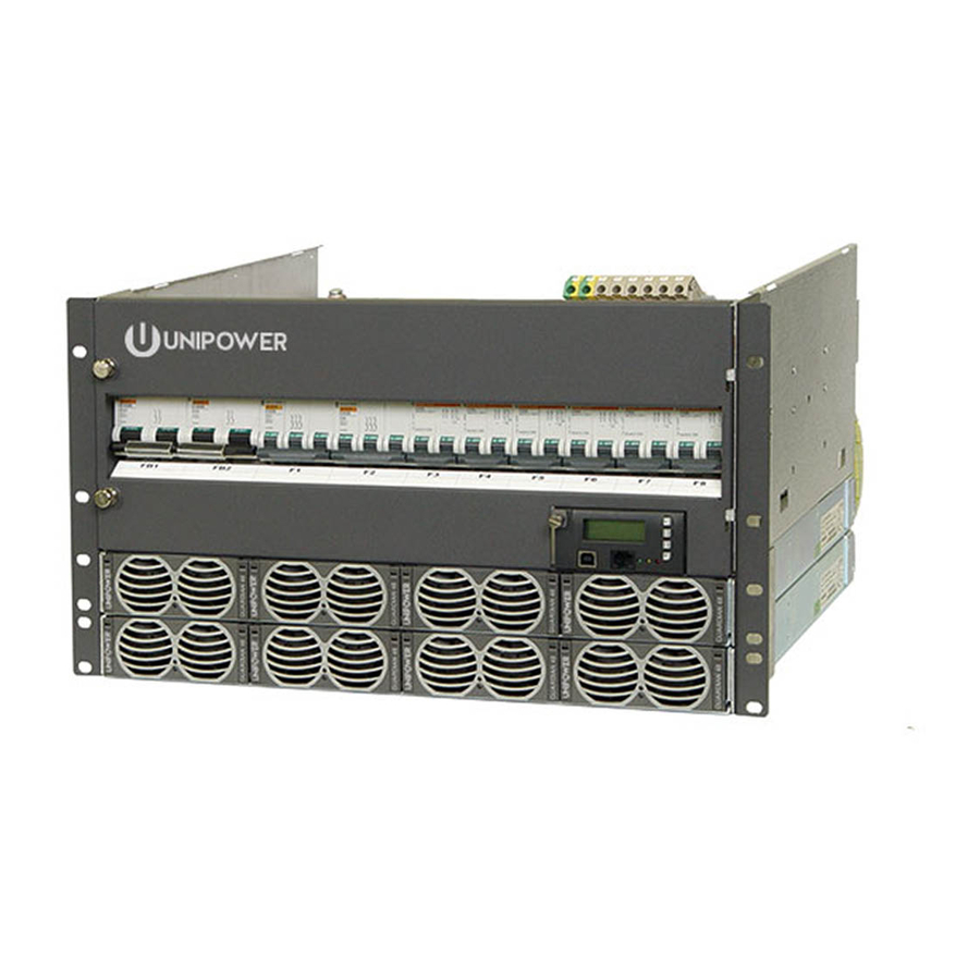
Guardian Access 5U/6U 19" Rack Mount
GDN.S.48.MS31
Instruction Manual
© 2021 UNIPOWER LLC
Document Number: MS0031-MAN rev. 7
All Rights Reserved
UNIPOWER, LLC
65 Industrial Park Rd
Dunlap, TN 37327
Phone: +1-954-346-2442
Toll Free: 1-800-440-3504
Web site:
www.unipowerco.com
Advertisement
Table of Contents
Troubleshooting

Related Manuals for Unipower Guardian Access


Summary of Contents for Unipower Guardian Access
- Page 1 P O W E R I N G T E C H N O L O G Y Power Supply System Guardian Access 5U/6U 19” Rack Mount GDN.S.48.MS31 Instruction Manual © 2021 UNIPOWER LLC Document Number: MS0031-MAN rev. 7 All Rights Reserved...
- Page 2 UNIPOWER LLC, which consent may be withheld by UNIPOWER LLC in its sole discretion. Users assume all risk and liability for, and agree to indemnify and defend UNIPOWER from and against any claims for personal injury (including death) or property damage resulting from any such use or application which is made in the absence of such prior express written consent.
-
Page 3: Table Of Contents
P O W E R I N G T E C H N O L O G Y Contents Chapter 1 About This Manual ......................6 1.1 Objectives ..........................6 1.2 Audience ..........................6 1.3 Document Key ........................6 1.4 Feedback & Support .......................7 Chapter 2 System Description ......................8 2.1 Overview ..........................8 2.2 Principal of Operation ......................9... - Page 4 P O W E R I N G T E C H N O L O G Y 4.5 Mounting in a Cabinet / Relay Rack ..................23 4.6 Removing the Covers (Optional) ..................24 4.7 Connecting Grounding Cable ....................24 4.8 AC Input Connection ......................25 4.9 DC Load Connection ......................27 4.10 Battery Cable and Connection ....................28 4.11 Battery Installation ........................29...
- Page 5 P O W E R I N G T E C H N O L O G Y FIGURES Figure 2-1 Power System Overview (6U system shown) .............8 Figure 2-2 Principal of Operation ....................9 Figure 2-3 Guardian Rectifier .....................13 Figure 2-4 Guardian Rectifier Shelf ....................14 Figure 4-1 Mounting the Subrack (6U system shown) ...............23 Figure 4-2 Removing the Top Cover ...................24 Figure 4-3 Grounding Connection ....................25...
-
Page 6: Chapter 1 About This Manual
Chapter 1 About This Manual P O W E R I N G T E C H N O L O G Y 1. About This Manual This chapter contains an overview of the information that is presented in this Power System Manual. - Page 7 • What actions have been taken since the problem occurred? 1.5 Disclaimer UNIPOWER is not responsible for system problems that are the result of installation or modification of the instructions provided in this manual. Document Number: MS0031-MAN rev. 7 Page 7...
-
Page 8: Chapter 2 System Description
Options include battery and load disconnects, AC surge protection and DC distribution. The Guardian access system is ideal for radio base stations, broadband nodes and core sites. The power system can be managed locally through messages and alarms displayed on the LCD screen of the system controller, remotely using the PC-based PowComTM software, or through a web browser with Ethernet connection. -
Page 9: Principal Of Operation
P O W E R I N G T E C H N O L O G Y 2.2 Principal of Operation The power system is normally configured with N+1 redundancy, with N as the number of rectifier modules necessary for feeding the load and charging the battery and 1 as the redundant rectifier module. -
Page 10: System Parameters
P O W E R I N G T E C H N O L O G Y 2.3 System Parameters OUTPUT Power (max) 21.4kW load + 1.8kW battery charge @ 230/400VAC nominal 13.6kW including battery recharge @ 120VAC nominal Output Current (max) 400A load + 33.6A battery charge @ 230/400VAC nominal 254A including battery recharge @ 120VAC nominal... - Page 11 P O W E R I N G T E C H N O L O G Y MECHANICAL Dimensions (WxHxD) 18.9”/481mm x 8.7”/221mm x 15.6”/396mm - 5U Without Covers 18.9”/481mm x 8.7”/221mm x 16.9”/430mm - 5U With Covers 18.9”/481mm x 10.4”/264mm x 15.6”/396mm - 6U Without Covers 18.9”/481mm x 10.4”/264mm x 16.9”/430mm - 6U With Covers Mounting Options 19”...
-
Page 12: System Components
T E C H N O L O G Y 2.4 System Components With the exception of the rectifier modules the Guardian Access system is delivered with all components mounted according to the ordered configuration. The main components are described below and in later chapters of this manual. -
Page 13: Rectifier Module
P O W E R I N G T E C H N O L O G Y If disconnection occurs, the batteries will be reconnected when mains supply returns. 2.3.2.2 Partial Load Disconnection / Load Shedding (PLD) Partial load disconnection can be configured to be voltage or time dependent, this is selected when ordering the power system. -
Page 14: Rectifier Shelf
P O W E R I N G T E C H N O L O G Y 2.4.4 Rectifier Shelf The rectifier shelf is used for interconnecting the rectifier modules. Each rectifier shelf has four module positions. Module position are numbered from the left to right as viewed from the front. -
Page 15: Chapter 3 System Safety
Chapter 3 System Safety P O W E R I N G T E C H N O L O G Y 3.1 Safety Warnings and Guidelines The following warnings and guidelines should be followed by properly trained and authorized personnel when installing, operating, commissioning or maintaining this equipment. -
Page 16: Installation Warning
NOTE This may be disregarded for systems delivered in a UNIPOWER Outdoor enclosure. 3.1.5 System Enclosure Appropriate measures need to be taken to avoid intrusion of any unwanted objects or insects into conductive areas of the power system as there is a potential risk of system damage. -
Page 17: Electrical Safety Warnings
P O W E R I N G T E C H N O L O G Y 3.1.8 Electrical Safety Warnings The following are electrical safety recommendations for working near the Power System: WARNING Observe low voltage safety precautions before attempting to work on the system when power is connected. -
Page 18: Grounding
P O W E R I N G T E C H N O L O G Y 3.1.9 Grounding WARNING Grounding connection must be performed before operating the system. Refer to local codes, e.g. ANSI, CEC, NEC, T1-333, ETSI 300-386-TC specifying the connection of power system to building ground. -
Page 19: In Case Of An Accident
P O W E R I N G T E C H N O L O G Y 3.1.11 In Case of an Accident In the event of an accident resulting in injury: 1. Use caution and check for hazards in the area. 2. -
Page 20: Breakers
P O W E R I N G T E C H N O L O G Y 3.2.5 Breakers Maximum 45°C operating ambient: 1. Up to 32A CB maximum load must not exceed 80% of it’s rating. 2. 40A CB maximum load shall not exceed 30A. 3. -
Page 21: Chapter 4 Installation Guide
Chapter 4 Installation Guide P O W E R I N G T E C H N O L O G Y WARNING There are potential hazards related to installing this power system. It is important to carefully read and understand the contents of the Safety chapter before performing system installation. -
Page 22: Cable Size
P O W E R I N G T E C H N O L O G Y CAUTION Care must be taken when installing this system. The units can be damaged and can cause damage if not handled with care. Pay particular attention to the order in which units are installed. -
Page 23: Mounting In A Cabinet / Relay Rack
P O W E R I N G T E C H N O L O G Y 4.5 Mounting in a Cabinet / Relay Rack Two mounting brackets installed on the front left and right side of the power system enable secure fastening of the subrack to a cabinet or a relay rack. -
Page 24: Removing The Covers (Optional)
P O W E R I N G T E C H N O L O G Y 4.6 Removing the Covers (Optional) The transparent plastic top cover and the front door of the Distribution Unit should be removed for connecting AC cables, alarm cables and DC cables. 1. -
Page 25: Ac Input Connection
P O W E R I N G T E C H N O L O G Y Single Fixing Two Fixing Main Earth Terminal Figure 4-3 Grounding Connection 4.8 AC Input Connection WARNING Ensure that mains input is turned off before connecting. The grounding must be connected to PE terminal as first. -
Page 26: Figure 4-4 Ac Input Terminal Block (1-Phase)
P O W E R I N G T E C H N O L O G Y 4.8.1 Standard (combined) Input Mains input terminal blocks are located on the rear left side of distribution unit. Mains cable size is max. 16mm². The mains input terminal blocks can be connected to: •... - Page 27 P O W E R I N G T E C H N O L O G Y 4.8.2 Individual (per rectifier position) Input Mains inputs terminal blocks are located across the rear of the distribution shelf behind a removeable access panel. Figure 4-7 below represents the view from above when looking from the rear of the system.
-
Page 28: Dc Load Connection
P O W E R I N G T E C H N O L O G Y 4.9 DC Load Connection This section details how to connect the loads to the DC load breakers. Use suitably sized cables according to Table 4-1 on page 22. Check that all the MCB’s are in the OFF position. -
Page 29: Battery Cable And Connection
P O W E R I N G T E C H N O L O G Y 4.10 Battery Cable and Connection If ordered, battery cables are pre-connected to the system battery breakers. If not, use suitably rated cable size (see Table 4-1 on page 22) and follow steps 1 to 4 below. Battery Connection Points on the PBDU and Battery Distribution are shown in Figure 4-9. -
Page 30: Battery Installation
P O W E R I N G T E C H N O L O G Y 4.11 Battery Installation The batteries should be handled according to the battery manufacturer’s recommendations. When placed into the cabinet, the recommended distance of 5-15mm between the battery blocks should be adhered to to ensure proper ventilation. -
Page 31: Alarm And Signal Connections
P O W E R I N G T E C H N O L O G Y 4.12 Alarm and Signal Connections Alarm connections are positioned on the right side of the PBDU on the Alarm interface board, see Figure 4-11. To connect the alarm cable to the alarm interface board, follow the steps below: 1. -
Page 32: Figure 4-11 Acx External Connection Board
P O W E R I N G T E C H N O L O G Y ACX External Connection Board: Select this if the ACX internal communication board is selected and a maximum of 4 alarm relay outputs are required. (Figure 4-12) ACX Alarm Relay Board: Select this if the ACX internal communication board is selected and 5 - 10 alarm relay outputs are required. -
Page 33: Symmetry Connection
P O W E R I N G T E C H N O L O G Y Blue Green Symmetry#1 Multi purpose 1-6 Blue Green Symmetry#2 Multi purpose 7-12 XC10 Blue Temperature Green TEMP1(BATT) sensor Blue Temperature Green TEMP2(AMB) sensor XC11 Alarm 1... -
Page 34: Temperature Sensor Connection
P O W E R I N G T E C H N O L O G Y Figure 4-13 2-block Symmetry Measurement (for illustration only) For 4-block measurement fix the 3 wires (red, green and blue) of the symmetry cable to individual cable lugs. -
Page 35: Figure 4-15 Temperature Sensor Connection
P O W E R I N G T E C H N O L O G Y Fasten the temperature sensor in the middle of the battery bank, Figure 4-15. Temp. Sensor Figure 4-15 Temperature Sensor Connection NOTE The temperature compensation factor can be set only for temperature sensor 1. Ambient Temperature Temperature sensor 2 allows a second temperature reading, most commonly the ambient temperature around the system. -
Page 36: Rectifier Installation
P O W E R I N G T E C H N O L O G Y 4.15 Rectifier Installation NOTE Ensure that the rectifier handle is in the OPEN position (forms 35-40° angle with rectifier body) before inserting the module into the slot. Rectifier module should be installed starting from the bottom left position in the rectifier shelf. -
Page 37: Chapter 5 Commissioning
Chapter 5 Commissioning P O W E R I N G T E C H N O L O G Y 5.1 Commissioning Overview Before delivery the system was thoroughly inspected and tested. The following chapter is a guide to the set-up and operation of the control functions of the system. NOTE Before starting commissioning read the product description for the individual components. -
Page 38: Commissioning Procedure
P O W E R I N G T E C H N O L O G Y 5.4 Commissioning procedure 1. Remove the covers and check that all connections are made according to the installation drawing. Verify that all connections are properly tightened with sufficient torque. 2. -
Page 39: Test Of Output Voltage
P O W E R I N G T E C H N O L O G Y 5.5 Test of output voltage 5.5.1 Float charge (U1) Ensure that the controller is operating. Connect a load, approx. 50% of total capacity, to the system. Check the voltage according to the battery manufacturer’s requirements. -
Page 40: Battery Supervision
Temperature compensation is factory pre-set. Check that the temp. probe is activated and verify that the compensation level is in accordance with the battery manufacturer’s requirements. (If no compensation level is available from the battery manufacture, UNIPOWER recommends that it is set to 0.5V). -
Page 41: Commissioning Record
P O W E R I N G T E C H N O L O G Y 5.8 Commissioning record This is a step-by-step commissioning record for easy commissioning of Power Supply Systems. Do not continue if any faults occur during this commissioning. The checkpoints are to be considered as a minimum for commissioning of the system. -
Page 42: Chapter 6 Maintenance & Troubleshooting
Chapter 6 Maintenance & Troubleshooting P O W E R I N G T E C H N O L O G Y 6.1 Maintenance 6.1.1 Checking Terminal Connection The connections on the terminal blocks and circuit breakers must be checked according to the Table 6-1 at least once a year. -
Page 43: Troubleshooting
If the first step of the recommendation does not solve the problem continue to the next one. NOTE If the malfunctioning of the system persists, please contact UNIPOWER technical support. NOTE For a description of Alarms and Messages generated by the system controller see... - Page 44 P O W E R I N G T E C H N O L O G Y Fault Possible Cause Suggestion/Solution Check if module sends alarm flag. Module Failure Faulty module. AC OFF on a single rectifier (if more Verify the AC voltage to the failed than one rectifier is installed).
- Page 45 P O W E R I N G T E C H N O L O G Y Fault Possible Cause Suggestion/Solution Communication Module failure. Check the non-communicating Failure address Modules not installed in the correct If the rectifier address does not position.
- Page 46 P O W E R I N G T E C H N O L O G Y Fault Possible Cause Suggestion/Solution Symmetry Fault Battery at end of life. Verify the battery condition. Wrong symmetry cable connection. Verify the symmetry cable connection.
-
Page 47: Chapter 7 Replacing Modules
Chapter 7 Replacing Modules P O W E R I N G T E C H N O L O G Y 7.1 Controller Replacement A faulty Controller can be easily replaced with a new one: 1. Loosen the front screw in the top left corner of the controller front panel using a flat screwdriver. -
Page 48: Surge Protection Device Replacement
5. Reinstall the top cover. 6. Switch on AC input power. This document is believed to be correct at time of publication and UNIPOWER LLC accepts no responsibility for consequences from printing errors or inaccuracies. Specifications are subject to change without notice. -
Page 49: Appendix A - Drawings
Appendix A - Drawings P O W E R I N G T E C H N O L O G Y A.1 System Unit Layout BATTERY BREAKERS LOAD BREAKERS (2, 4, or 6 positions) (15, 18 or 21 positions) CONTROLLER RECTIFIERS (4 max. -
Page 50: Installation Details - Connections
P O W E R I N G T E C H N O L O G Y A.2 Installation Details - Connections Symmetry cable connections Table shows different ways of battery symmetry cable connections depending on actual software (see controller software sheet) Battery type: 4 blocks Battery type: 2 blocks (-)24V... -
Page 51: Block Diagram & Schematics
P O W E R I N G T E C H N O L O G Y A.3 Block Diagram & Schematics Block Diagram See schematic Guardian diagram Subrack GDN Shelf 1 X6 com 5x AC/DC Rectifier X7 com GDN Shelf 2 X6 com 5x AC/DC Rectifier... - Page 52 P O W E R I N G T E C H N O L O G Y PBDU Schematic 0V Bus 0V Battery 0V Load See Block -48V Bus diagram Shunt - Battery 1 +/A2 -/A1 - Battery n - Load 1 - Load n Optional PLD...
- Page 53 P O W E R I N G T E C H N O L O G Y Rectifier Sub-rack Schematic Document Number: MS0031-MAN rev. 7 Page 53 guardian_access_ms31-man-rev7-0521.indd...
-
Page 54: Detailed Dimensions
P O W E R I N G T E C H N O L O G Y A.4 Detailed Dimensions 5U - 4 RECTIFIERS 19 (481) 18 (461) 0.5 (13) x 0.25 (6.5) SLOT HOLE 1.75 (44.45) 2.25 (57.15) 1.75 (44.45) 1.49... - Page 55 P O W E R I N G T E C H N O L O G Y 6U - 8 RECTIFIERS 19 (481) 18 (461) 0.5 (13) x 0.25 (6.5) P O W E R I N G T E C H N O L O G Y SLOT HOLE 1.75 (44.45)
Need help?
Do you have a question about the Guardian Access and is the answer not in the manual?
Questions and answers