Table of Contents
Advertisement
Quick Links
P O W E R I N G
T E C H N O L O G Y
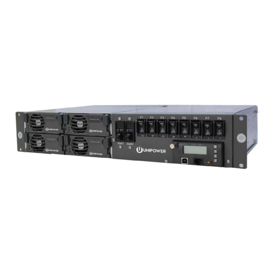
Power Supply System
Aspiro 2U Front Access
Instruction Manual
www.unipowerco.com
© 2016 UNIPOWER LLC
Document Number: ASPIRO2U-3
All Rights Reserved
aspiro2u_m23-man-rev3-0516.indd
UNIPOWER LLC • 3900 Coral Ridge Drive, Coral Springs, Florida 33065, USA • sales@unipowerco.com
North America: +1 954-905-1071 • Latin America: +1 954-905-1078 • Europe: +44 1903 768200
Advertisement
Table of Contents

Related Manuals for Unipower XPGe12.48


Summary of Contents for Unipower XPGe12.48
- Page 1 © 2016 UNIPOWER LLC Document Number: ASPIRO2U-3 All Rights Reserved aspiro2u_m23-man-rev3-0516.indd UNIPOWER LLC • 3900 Coral Ridge Drive, Coral Springs, Florida 33065, USA • sales@unipowerco.com North America: +1 954-905-1071 • Latin America: +1 954-905-1078 • Europe: +44 1903 768200...
- Page 2 UNIPOWER LLC, which consent may be withheld by UNIPOWER LLC in its sole discretion. Users assume all risk and liability for, and agree to indemnify and defend UNIPOWER from and against any claims for personal injury (including death) or property damage resulting from any such use or application which is made in the absence of such prior express written consent.
-
Page 3: Table Of Contents
P O W E R I N G T E C H N O L O G Y Contents Chapter 1 About This Manual ......................6 1.1 Objectives ..........................6 1.2 Audience ..........................6 1.3 Document Key ........................6 1.4 Feedback & Support .......................7 1.6 Disclaimer ..........................7 Chapter 2 Aspiro System Description ..................8 2.1 Overview ..........................8... - Page 4 Chapter 7 Replacing Modules .....................40 7.1 Controller Replacement ......................40 7.2 Rectifier Replacement ......................41 7.2.1 XR04.48 / XR08.48 Replacement ................41 7.2.2 XPGe12.48 Replacement .....................41 7.3 Battery and Load Breakers Replacement ................42 7.4 Surge Protection Device Replacement ..................44 7.5 Other Requirements ......................44 Appendix A - Drawings ........................45...
- Page 5 Unlocking the Controller ..................40 Figure 7-2 Removing the Controller ...................40 Figure 7-3 Replacing an XR04.48 or XR08.48 Rectifier ............41 Figure 7-4 Replacing an XPGe12.48 Rectifier ................42 Figure 7-5 Removing the front panel ..................42 Figure 7-6 Removing the top cover ....................43 Figure 7-7 Pulling out a faulty breaker ..................43...
-
Page 6: Chapter 1 About This Manual
Chapter 1 About This Manual P O W E R I N G T E C H N O L O G Y 1. About This Manual This chapter contains an overview of the information that is presented in this Power System Manual. -
Page 7: Feedback & Support
This manual is intended for two-sided black and white printing. Some pages are intentionally left blank. 1.6 Disclaimer UNIPOWER is not responsible for system problems that are the result of installation or modification of the instructions provided in this manual. Manual No. aspiro2u-3 aspiro2u_m23-man-rev3-0516.indd... -
Page 8: Chapter 2 Aspiro System Description
BTS Cells, Enterprise, E911, and GSM-R. The Aspiro shelf system utilizes efficient, dense, and reliable plug-in rectifier modules XR04.48, XR08.48 or XPGe12.48, with output power available at either 400W, 800W or 1200W per rectifier, based upon a soft-switching approach. Features include wide input operating range, wide operating temperature, full self-protection and three LEDs for immediate rectifier status indication. -
Page 9: System Parameters
P O W E R I N G T E C H N O L O G Y 2.2 System Parameters OUTPUT Power (max) 4800W (XPGe12.48G), 3200W (XR08.48G), 1600W (XR04.48G) Output Current (max) 60A @ 55°C (XPGe12.48G & XR08.48G) 30A @ 55°C (XR04.48G) Voltage 46-57VDC INPUT... - Page 10 P O W E R I N G T E C H N O L O G Y RECTIFIER MODEL XPGe12.48 XR08.48 XR04.48 Efficiency 95% typical @ I 90% typical @ I 88% typical @ I Input Current (max) <7.3A <10.5A...
-
Page 11: System Components
P O W E R I N G T E C H N O L O G Y 2.3 System Components The Aspiro system is delivered with all components mounted according to the ordered configuration. The main components are described below and in later chapters of the manual. 2.3.1 System Controller The Aspiro power system can be controlled by the ACC Extended or PCC controller. -
Page 12: Rectifier Module
The output voltage of the rectifier is automatically adjusted to the required voltage by the controller. Figure 2-2 XPGe12.48 and XR04.48/XR08.48 XPGe12.48 rectifiers cannot be used in the same rack as XR04.48 / XR08.48 rectifiers. CAUTION XPGe12.48 rectifiers cannot be used in the same system as XR04.48/ XR08.48 rectifiers. -
Page 13: Chapter 3 System Safety
Chapter 3 System Safety P O W E R I N G T E C H N O L O G Y 3.1 Safety Warnings and Guidelines The following warnings and guidelines should be followed by properly trained and authorized personnel when installing, operating, commissioning or maintaining this equipment. -
Page 14: Installation Warning
NOTE This may be disregarded for systems delivered in a UNIPOWER Outdoor enclosure. 3.1.5 System Enclosure Appropriate measures need to be taken to avoid intrusion of any unwanted objects or insects into conductive areas of the power system as there is a potential risk of system damage. -
Page 15: Electrical Safety Warnings
P O W E R I N G T E C H N O L O G Y 3.1.7 Electrical Safety Warnings The following are electrical safety recommendations for working near the Power System: WARNING Observe low voltage safety precautions before attempting to work on the system when power is connected. -
Page 16: Grounding
P O W E R I N G T E C H N O L O G Y 3.1.8 Grounding WARNING Grounding connection must be performed before operating the system. Refer to local codes, e.g. ANSI, CEC, NEC, T1-333, ETSI 300-386-TC specifying the connection of power system to building ground. -
Page 17: In Case Of An Accident
P O W E R I N G T E C H N O L O G Y 3.1.10 In Case of an Accident In the event of an accident resulting in injury: 1. Use caution and check for hazards in the area. 2. -
Page 18: Breakers
P O W E R I N G T E C H N O L O G Y 3.2.5 Breakers CAUTION Breakers should always be replaced with the same type and rating in order to avoid damage to system components. 3.2.6 Hot Surfaces CAUTION Areas of the Power System may become hot. -
Page 19: Chapter 4 Installation Guide
Chapter 4 Installation Guide P O W E R I N G T E C H N O L O G Y 4.1 Unpacking Check that the received equipment is in accordance with the packing list. Ensure that the cabinet and the equipment have not been damaged during transportation. Report any parts that are damaged, missing or incorrect. -
Page 20: Figure 4-1 System Mounting
P O W E R I N G T E C H N O L O G Y NOTE When mounting the system to an open frame, the brackets should be moved to the middle position. To mount the subrack into a cabinet, follow the steps below: 1. -
Page 21: Cable Entry
P O W E R I N G T E C H N O L O G Y 4. Then fasten the subrack, either with adjustable or fixed brackets, to the cabinet with four M6 x 12mm (2 on each side of the subrack). Tighten the screws to 6Nm, Figure 4-3. Figure 4-3 System Bracket Fixing 4.4 Cable Entry If the top distribution cover is installed, it should be removed for connecting AC, DC, alarm,... -
Page 22: Ac Input Connection
P O W E R I N G T E C H N O L O G Y 4.5 Grounding Connection The power system needs to be properly grounded to the rack or cabinet frame to ensure its safe and efficient operation, see Figure 4-5. Figure 4-5 Grounding Connection 4.6 AC Input Connection WARNING Ensure that mains input is turned off before connecting. -
Page 23: Dc Load Connection
P O W E R I N G T E C H N O L O G Y Figure 4-6 AC Input Terminal Block (1-phase) The mains input terminal blocks can be connected to: 3-phase 400VAC, 1-phase230 VAC or 2-phase 230VAC, see Figure 4-7. 1x230VAC 3x400VAC 2x230VAC... -
Page 24: Battery Connection
P O W E R I N G T E C H N O L O G Y • Insert a flat screw driver into the square hole of green spring terminal to compress the spring. • Push the stripped cable into the round hole of the same terminal. •... -
Page 25: Alarm And Signal Connections
P O W E R I N G T E C H N O L O G Y Battery -48 V Battery 0V Figure 4-9 Battery Connection 4.9 Alarm and Signal Connections For remote supervision of the alarms, there are a maximum 4 potential free alarm contacts available. -
Page 26: Symmetry Connection
P O W E R I N G T E C H N O L O G Y To connect the alarm cables to Alarm interface board, follow the steps below: 1. Remove the green plug from each connector. 2. Determine whether to reference normally closed or normally open with reference to common for each alarm contact. -
Page 27: Temperature Sensor Connection
P O W E R I N G T E C H N O L O G Y Figure 4-12 4-Block Symmetry Measurement (for illustration only) NOTE The interblock Connection Kit is not delivered with the system. 4.11 Temperature Sensor Connection NOTE The power system is usually delivered with pre-connected temperature sensor cables. -
Page 28: Rectifier Installation
3. a) For XR04.48/XR08.48 fully insert the rectifier by pushing it into the shelf, fasten the rectifier in the slot and tighten the screw with a screw driver. b) For XPGe12.48 fully insert the rectifier by pushing the handle towards the shelf. The rectifier handle will rise up and lock the rectifier into position. -
Page 29: Connection Of External Pdu To Dc Parallel Kit (Option)
P O W E R I N G T E C H N O L O G Y 4.13 Connection of External PDU to DC Parallel Kit (Option) 1. Turn OFF all the breakers and the AC input before installation. 2. -
Page 30: Chapter 5 Commissioning
Chapter 5 Commissioning P O W E R I N G T E C H N O L O G Y 5.1 Commissioning Overview Before delivery the system was thoroughly inspected and tested. The following chapter is a guide to the set-up and operation of the control functions of the system. NOTE Before starting commissioning read the product description for the individual components. -
Page 31: Commissioning Procedure
P O W E R I N G T E C H N O L O G Y 5.4 Commissioning procedure 1. Remove the covers and check that all connections are made according to the installation drawing. Verify that all connections are properly tightened with sufficient torque. 2. -
Page 32: Test Of Output Voltage
P O W E R I N G T E C H N O L O G Y 5.5 Test of output voltage 5.5.1 Float charge (U1) Ensure that the controller is operating. Connect a load, approx. 50% of total capacity, to the system. Check the voltage according to the battery manufacturer’s requirements. -
Page 33: Battery Supervision
Temperature compensation is factory pre-set. Check that the temp. probe is activated and verify that the compensation level is in accordance with the battery manufacturer’s requirements. (If no compensation level is available from the battery manufacture, UNIPOWER recommends that it is set to 0.5V). -
Page 34: Commissioning Record
P O W E R I N G T E C H N O L O G Y 5.8 Commissioning record This is a step-by-step commissioning record for easy commissioning of Power Supply Systems. Do not continue if any faults occur during this commissioning. The checkpoints are to be considered as a minimum for commissioning of the system. -
Page 35: Chapter 6 Maintenance & Troubleshooting
If the first step of the recommendation does not solve the problem continue to the next one. NOTE If the malfunctioning of the system persists, please contact UNIPOWER technical support. NOTE For a description of Alarms and Messages generated by the system controller see... - Page 36 P O W E R I N G T E C H N O L O G Y Fault Possible Cause Suggestion/Solution Module failure. Replace faulty module. Low System Voltage Loss of AC power. Verify AC input connection. Load exceeds module capacity. Add module to system.
- Page 37 P O W E R I N G T E C H N O L O G Y Fault Possible Cause Suggestion/Solution System voltage drops below the set Check the battery condition. Load/Battery limit. Disconnection Check the AC mains connection. System shutdown.
- Page 38 P O W E R I N G T E C H N O L O G Y Fault Possible Cause Suggestion/Solution Tripped load breaker / blown load Verify there is no short circuit in load Battery Fuse fuse or battery cabling. Failure Verify the breaker / fuse is correctly rated.
- Page 39 P O W E R I N G T E C H N O L O G Y If none of the above solves the problem please contact customer support. To phone us please visit http://www.unipowerco.com/contact/ and select Customer “Support/ Repairs”...
-
Page 40: Chapter 7 Replacing Modules
Chapter 7 Replacing Modules P O W E R I N G T E C H N O L O G Y 7.1 Controller Replacement A faulty Controller can be easily replaced with a new one: 1. Loosen the front screw in the top left corner of the controller front panel using a flat screwdriver, see Figure 7-1. -
Page 41: Rectifier Replacement
3. Replace rectifier. Make sure that the rectifier handle is in OPEN position (forms 35-40° angle with rectifier body) before XPGe12.48 is fully inserted in the slot. 4. Push both handles upwards until the left handle locks the rectifier into the correct position. -
Page 42: Battery And Load Breakers Replacement
P O W E R I N G T E C H N O L O G Y Figure 7-4 Replacing an XPGe12.48 Rectifier 7.3 Battery and Load Breakers Replacement WARNING Make sure the system is switched OFF. The power rack is designed front accessible for easy maintenance. Battery and load breakers can be replaced without removing the power rack from the cabinet. -
Page 43: Figure 7-6 Removing The Top Cover
P O W E R I N G T E C H N O L O G Y Figure 7-6 Removing the top cover 2. Pull out the faulty breakers Figure 7-7. Figure 7-7 Pulling out a faulty breaker 3. Install the correct breakers, front panel and the top cover. Manual No. -
Page 44: Surge Protection Device Replacement
This document is believed to be correct at time of publication and UNIPOWER LLC accepts no responsibility for consequences from printing errors or inaccuracies. Specifications are subject to change without notice. -
Page 45: Appendix A - Drawings
Appendix A - Drawings P O W E R I N G T E C H N O L O G Y Front View Layout Description Manual No. aspiro2u-3 aspiro2u_m23-man-rev3-0516.indd Page 45... - Page 46 P O W E R I N G T E C H N O L O G Y Installation Details - Connections Symmetry cable connections Table shows different ways of battery symmetry cable connections depending on actual software (see controller software sheet) Battery type: 2 blocks Battery type: 4 blocks Battery...
-
Page 47: Block Diagram
P O W E R I N G T E C H N O L O G Y Block Diagram -48V Rectifier backplane - Top RS485 Com. Rect#3: XPGe12.48/ Rect#4: XPGe12.48/ XR08.48/ XR04.48 XR08.48/ XR04.48 -48V Rectifier backplane -Bottom RS485 Com. - Page 48 P O W E R I N G T E C H N O L O G Y Detailed Dimensions - Fixed Bracket Option 3.0 (76.2) 11.63 (295.4) 2.95 (75) 12.69 (322.2) 3.5 (88) Note: ETSI mounting details are shown in green. aspiro2u_m23-man-rev3-0516.indd Manual No.
- Page 49 P O W E R I N G T E C H N O L O G Y Detailed Dimensions - Slide Bracket Option 3.0 (76.2) 2.95 (75) 0.98 (25) 11.63 (295.4) 12.69 (322.2) 1.75 (44.5) 3.5 (88) Note: ETSI mounting details are shown in green. Manual No.
Need help?
Do you have a question about the XPGe12.48 and is the answer not in the manual?
Questions and answers