Table of Contents
Advertisement
Quick Links
P O W E R I N G
Document Number: PM110-6500-00 rev2a
PM110-6500-00-rev2a-0117.indd
UNIPOWER LLC • 3900 Coral Ridge Drive, Coral Springs, Florida 33065, USA • sales@unipowerco.com
T E C H N O L O G Y
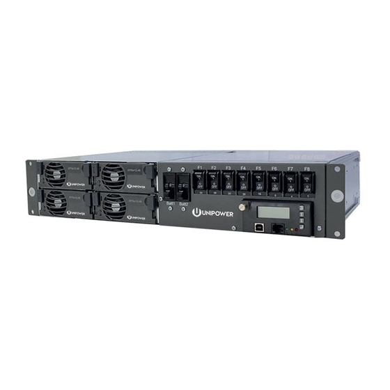
Power Supply System
Aspiro 1U in a 2U Enclosure
Instruction Manual
www.unipowerco.com
North America: +1 954-346-2442 • Latin America: +1 954-905-1078 • Europe: +44 1903 768200
© 2017 UNIPOWER LLC
All Rights Reserved
Advertisement
Table of Contents

Related Manuals for Unipower Aspiro 1U Enclosure


Summary of Contents for Unipower Aspiro 1U Enclosure
- Page 1 © 2017 UNIPOWER LLC Document Number: PM110-6500-00 rev2a All Rights Reserved PM110-6500-00-rev2a-0117.indd UNIPOWER LLC • 3900 Coral Ridge Drive, Coral Springs, Florida 33065, USA • sales@unipowerco.com North America: +1 954-346-2442 • Latin America: +1 954-905-1078 • Europe: +44 1903 768200...
- Page 2 UNIPOWER LLC, which consent may be withheld by UNIPOWER LLC in its sole discretion. Users assume all risk and liability for, and agree to indemnify and defend UNIPOWER from and against any claims for personal injury (including death) or property damage resulting from any such use or application which is made in the absence of such prior express written consent.
-
Page 3: Table Of Contents
P O W E R I N G T E C H N O L O G Y Contents Chapter 1 About This Manual ......................6 1.1 Objectives ..........................6 1.2 Audience ..........................6 1.3 Document Key .........................6 1.4 Feedback & Support .........................7 1.6 Disclaimer ..........................7 Chapter 2 Aspiro System Description ..................8 2.1 Overview ..........................8... - Page 4 P O W E R I N G T E C H N O L O G Y Chapter 4 Installation Guide ......................18 4.1 Introduction ..........................18 4.2 Unpacking ..........................18 4.3 Tools............................18 4.4 Rack Mounting ........................19 4.5 Rear Connections ........................20 4.5.1 Earth Connection (FRAME GROUND) ..............21 4.5.2...
- Page 5 P O W E R I N G T E C H N O L O G Y FIGURES Figure 2-1 Power System Overview .....................8 Figure 2-2 XPGe12.48 and XR04.48/XR08.48 ................12 Figure 4-1 Dimensional Drawing (Front and Top View) ............19 Figure 4-2 System Mounting (19”...
-
Page 6: Chapter 1 About This Manual
Chapter 1 About This Manual P O W E R I N G T E C H N O L O G Y 1. About This Manual This chapter contains an overview of the information that is presented in this Power System Manual. -
Page 7: Feedback & Support
This manual is intended for two-sided black and white printing. Some pages are intentionally left blank. 1.6 Disclaimer UNIPOWER is not responsible for system problems that are the result of installation or modification of the instructions provided in this manual. Manual No. PM110-6500-00 rev-2a Page 7 PM110-6500-00-rev2a-0117.indd... -
Page 8: Chapter 2 Aspiro System Description
Chapter 2 Aspiro System Description P O W E R I N G T E C H N O L O G Y 2.1 Overview Aspiro DC power systems offer a range of solutions for diverse applications such as broadband access, cable head ends, micro/pico BTS Cells, Enterprise, E911, and GSM-R. -
Page 9: System Parameters
P O W E R I N G T E C H N O L O G Y 2.3 System Parameters OUTPUT Power (max) 2400W @ >180VAC, 800W @ <180VAC Output Current 52A max. @ 46VDC, 45A nominal Voltage 46-57VDC INPUT Voltage 10-250VAC (per plug) - Page 10 P O W E R I N G T E C H N O L O G Y RECTIFIER MODEL XPGe12.48 XR08.48 XR04.48 Efficiency 95% typical @ I nom. 90% typical @ I nom. 88% typical @ I nom. Input Current (max) <7.3A <10.5A <5.3A...
-
Page 11: System Components
ACC Extended (ACX): http://www.unipowerco.com/pdf/acc-man.pdf PCC: http://www.unipowerco.com/pdf/pcc-man.pdf The system can be remotely managed using UNIPOWER’s PowCom™ which works in conjunction with the controller. This is covered in its own manual which is available at http://www.unipowerco.com/pdf/powcom-man.pdf. 2.4.2 DC Distribution DC Distribution consists of 1 x 40A battery and 4 x 15A load breakers. -
Page 12: Rectifier Module
P O W E R I N G T E C H N O L O G Y 2.4.4 Rectifier Module The Fan-Cooled XPGe12.48 (1200W), XR08.48 (800W) and XR04.48 (400W) rectifiers are modular power supplies designed for parallel operation and hot-plug installation in the Aspiro Power Systems. -
Page 13: Chapter 3 System Safety
Chapter 3 System Safety P O W E R I N G T E C H N O L O G Y 3.1 Safety Warnings and Guidelines The following warnings and guidelines should be followed by properly trained and authorized personnel when installing, operating, commissioning or maintaining this equipment. -
Page 14: Electrical And Fire Enclosure
Appropriate measures need to be taken to avoid intrusion of any unwanted objects or insects into conductive areas of the power system as there is a potential risk of system damage. Disclaimer: UNIPOWER LLC assumes no liability or responsibility for system failures resulting from inappropriate enclosure around the system. -
Page 15: Emc Considerations
• Consult the dealer or an experienced radio/TV technician for help. WARNING changes or modifications not expressly approved by UNIPOWER could void the user’s authority to operate the equipment. 3.1.9 Grounding WARNING Proper 3-wire AC power cord must be connected to a properly grounded outlet. -
Page 16: Batteries
P O W E R I N G T E C H N O L O G Y 3.1.10 Batteries WARNING When installing or replacing batteries, there is risk of explosion if an incorrect battery type is used. 3.1.10.1 Lead Acid Batteries WARNING This equipment may use Lead Acid Batteries. -
Page 17: Caution
P O W E R I N G T E C H N O L O G Y 3.2 Caution 3.2.1 Storage and Transportation CAUTION During storage and transportation, the units must remain in their original packages in order to avoid mechanical damage, maintain traceability, and protect the units against electrostatic discharge. -
Page 18: Chapter 4 Installation Guide
Chapter 4 Installation Guide P O W E R I N G T E C H N O L O G Y WARNING There are potential hazards related to installing this power system. It is important to carefully read and understand the contents of Chapter 3 System Safety before performing system installation. -
Page 19: Rack Mounting
P O W E R I N G T E C H N O L O G Y 4.4 Rack Mounting The power system is designed for 19 inch rack mounting with 1” c-c mounting holes. See Figure 4-1. The brackets are front mounted. There needs to be sufficient clearance at the front for rectifier installation, and at the rear for connections. -
Page 20: Rear Connections
P O W E R I N G T E C H N O L O G Y Aspiro system can be easily mounted to a rack using the taptite screws to fasten the mounting brackets to the rack as shown in Figure 4-2. NOTE It is recommended to remove the rectifiers before installing the shelf to the cabinet or rack. -
Page 21: Earth Connection (Frame Ground)
P O W E R I N G T E C H N O L O G Y 4.5.1 Earth Connection (FRAME GROUND) WARNING The power system is internally grounded. Ground is achieved through the AC power cord. 4.5.2 Mains Connection CAUTION Depending on deployment region with regards to lightning strikes and heavy inductive energy, it is highly recommended to install AC Surge Protection Class C at the electrical panel. - Page 22 P O W E R I N G T E C H N O L O G Y For remote supervision of alarms, there are 4 potential free alarm contacts available. Each alarm contact represents different condition. Multi Purpose Voltage Inputs 1-12 can be reconfigured as external analog inputs.
-
Page 23: Figure 4-5 Signal Pin Designations
P O W E R I N G T E C H N O L O G Y Battery Ambient Temp. Temp. 10 11 12 13 14 15 16 17 18 10 11 12 13 14 15 16 17 18 Alarm Condition Shown Figure 4-5 Signal Pin Designations Manual No. -
Page 24: Dc Load Connections
P O W E R I N G T E C H N O L O G Y To connect: 1. Release a connector from the terminal using needle-nose pliers and pull it out. 2. Remove sufficient insulation from the cables and insert stripped cables into the appropriate connector. -
Page 25: Battery Connections
P O W E R I N G T E C H N O L O G Y Load Breaker Size Wire Size 2.5/14 /AWG] Table 4-2 Cable Sizes - Load 4.5.5 Battery Connections WARNING Improper handling with batteries can be dangerous. Please read and understand the information in the Safety chapter before connecting batteries. -
Page 26: Temperature Sensor Connection
P O W E R I N G T E C H N O L O G Y 3. Fix the 3 wires (red, green and blue) of the symmetry cable to individual cable lugs. Color coding of the cables must be respected for proper symmetry measurement see Figure 4-9. -
Page 27: Figure 4-10 Temperature Sensor Connection
P O W E R I N G T E C H N O L O G Y Temp. Sensor Figure 4-10 Temperature Sensor Connection NOTE See Figures 4-5 and 4-6 for connection to the system. Manual No. PM110-6500-00 rev-2a Page 27 PM110-6500-00-rev2a-0117.indd... -
Page 28: Chapter 5 Commissioning
Chapter 5 Commissioning P O W E R I N G T E C H N O L O G Y 5.1 Commissioning Overview Before delivery the system was thoroughly inspected and tested. The following chapter is a guide to the set-up and operation of the control functions of the system. NOTE Before starting commissioning read the product description for the individual components. -
Page 29: Commissioning Procedure
P O W E R I N G T E C H N O L O G Y 5.4 Commissioning procedure 1. Remove the alarm cover and check that all connections are made according to the installation drawing. Verify that all connections are properly tightened with sufficient torque. -
Page 30: Test Of Output Voltage
P O W E R I N G T E C H N O L O G Y 5.5 Test of output voltage 5.5.1 Float charge (U1) Ensure that the controller is operating. Connect a load, approx. 50% of total capacity, to the system. Check the voltage according to the battery manufacturer’s requirements. -
Page 31: Battery Supervision
Temperature compensation is factory preset. Check that the temp. probe is activated and verify that the compensation level is in accordance with the battery manufacturer’s requirements. (If no compensation level is available from the battery manufacture, UNIPOWER recommends that it is set to 0.5V). -
Page 32: Commissioning Record
P O W E R I N G T E C H N O L O G Y 5.8 Commissioning record This is a step-by-step commissioning record for easy commissioning of Power Supply Systems. Do not continue if any faults occur during this commissioning. The checkpoints are to be considered as a minimum for commissioning of the system. -
Page 33: Chapter 6 Maintenance & Troubleshooting
If the first step of the recommendation does not solve the problem continue to the next one. NOTE If the malfunctioning of the system persists, please contact UNIPOWER technical support. NOTE For a description of Alarms and Messages generated by the system controller see... - Page 34 P O W E R I N G T E C H N O L O G Y Fault Possible Cause Suggestion/Solution Module failure. Replace the faulty module. High System Voltage System voltage exceeds the set limit. Check the High Voltage Alarm limit setting.
- Page 35 P O W E R I N G T E C H N O L O G Y Fault Possible Cause Suggestion/Solution System voltage drops below the set Check the battery condition. Load/Battery limit. Disconnection Check the AC mains connection. System shutdown.
- Page 36 P O W E R I N G T E C H N O L O G Y Fault Possible Cause Suggestion/Solution Battery temperature exceeded the set Check the cooling or ventilation. High Battery limit. Temperature Verify the battery condition. Check the Battery Current Limit.
-
Page 37: Chapter 7 Replacing Modules
Chapter 7 Replacing Modules P O W E R I N G T E C H N O L O G Y 7.1 Controller Replacement A blank panel or faulty Controller can be easily replaced with a new controller: 1. Loosen the front screw(s) at the top of the controller or blanking panel using a flat or Pozidrive screwdriver as appropriate, see Figure 7-1. -
Page 38: Rectifier Replacement
P O W E R I N G T E C H N O L O G Y 7.2 Rectifier Replacement NOTE Rectifiers can be hot-swapped. CAUTION Do not mix rectifier types in a single system. 7.2.1 XR04.48 / XR08.48 Replacement To replace an XR04.48 or XR08.48 rectifier, follow the steps below: 1. -
Page 39: Xpge12.48 Replacement
WARNING Breakers are not field replaceable. To replace a faulty circuit breaker, send complete enclosure to an authorized repair facility. This document is believed to be correct at time of publication and UNIPOWER LLC accepts no responsibility for consequences from printing errors or inaccuracies. Specifications are subject to change without notice. -
Page 40: Appendix A - Block Diagram
Appendix A - Block Diagram P O W E R I N G T E C H N O L O G Y RECTIFIER SLOT #1 AC Input (CONNECTED TO AC INPUT 1) AC Input 1 XPGe12.48 or XR08.48 or XR04.48 AC Input 2 RS485 Com. -
Page 41: Appendix B - Mating Connector Details
Appendix B - Mating Connector Details P O W E R I N G T E C H N O L O G Y ED991-5002-B2 Issue 3 Manual No. PM110-6500-00 rev-2a Page 41 PM110-6500-00-rev2a-0117.indd...
Need help?
Do you have a question about the Aspiro 1U Enclosure and is the answer not in the manual?
Questions and answers