Sign In
Upload
Manuals
Brands
JUMO Manuals
Controller
DICON touch
JUMO DICON touch Process Controller Manuals
Manuals and User Guides for JUMO DICON touch Process Controller. We have
6
JUMO DICON touch Process Controller manuals available for free PDF download: Operating Manual, Quick Start Manual, Interface Manual, Manual, Datasheet
JUMO DICON touch Operating Manual (196 pages)
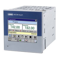
Two/Four-Channel Process and Program Controller with Paperless Recorder and 8.9 cm 3.5" Touchscreen
Brand:
JUMO
| Category:
Controller
| Size: 10 MB
Table of Contents
Table of Contents
3
1 Introduction
9
Safety Information
9
Warning Symbols
9
Note Signs
9
Display Types
10
Description
11
Block Diagram
12
2 Identifying the Device Version
13
Order Details
13
Scope of Delivery
15
General Accessories
15
Accessories
16
Nameplate
17
3 Mounting
19
Mounting Site and Climatic Conditions
19
Electrical Data
19
Environmental Influences
19
Housing
19
Dimensions
20
Close Mounting
21
Installation in Panel Cut-Out
21
Care and Treatment of the
21
4 Electrical Connection
23
Installation Notes
23
Lines, Shielding, and Grounding
23
Electrical Safety
23
Intended Use, Misuse
24
Galvanic Isolation
25
Connection Diagram
26
Connection Elements
26
Analog Inputs
27
Probes for Air
28
Probes for Water and Oil
29
Probes for Water, Oil, and Air
29
Analog Outputs
30
Digital Inputs
30
Digital Outputs
30
Digital Outputs
32
Voltage Supply (According to Nameplate)
32
Interfaces
34
5 Operation
37
Display and Operating Concept
37
Device Menu
38
Alarm and Event List
38
Function Buttons, History, and Channel Changeover
38
Screens in the Operating Loop
39
Controller Screen 1 to 4 and Controller Overview Screens 1, 2
39
Program Controller
41
General Screens 1, 2
42
Recording View 1, 2
43
Process Screen 1 to 4
43
6 Login
45
Login
46
Logout
46
Changing the Password
46
7 User Level (Log-In)
47
Example 4 Transferring Controller Setpoint Values to the User Level
47
8 Program Administration
49
Entering Program Profiles
49
On the Device
49
About the Setup Program
50
Section Run Time
51
Setpoint Value 1 to 4
51
Operating Contacts
51
Tolerance Band
51
Number of Repetitions
52
Start Section
52
Parameter Block
52
9 Device Info
53
General Information
53
Version, Motherboard, Ethernet Information
53
Slots
53
Inputs/Outputs
54
Digital and Analog Inputs, Digital and Analog Outputs, External Digital, and External Analog Inputs
54
Functions
55
Math, Logic Signal, Limit Value Outputs
55
Timer Signal, Digital Control Signals, Operating Contacts, Controller, Analog Flag, Digital Flag
55
Ethernet
56
Profinet
56
10 Functional Level
57
General Information
57
Activating the Functional Level
57
11 Parameterization
59
Date and Time
59
Daylight Saving Time
59
Controller/Parameter Blocks
60
Setpoint Values
64
Entering the Values on the Device
64
Entering the Values Using the Setup Program
65
12 Configuration
67
Analog Selector
67
Digital Selector
68
Basic Settings
72
Digital Inputs IN1 to 7
74
Analog Inputs IN8, IN9, IN10, IN11
75
Alarms
78
Controller 1 to 4
79
Controller Configuration
79
Controller Inputs
82
Controller Self-Optimization
84
Starting Autotuning (SO) on the Device
89
Control Loop Monitoring
91
Output Level Monitoring
94
Controller Setpoint Values
97
Ramp Function
99
Digital Outputs
101
Switching Digital Outputs to Logic Level 1 as a Fixed Setting
102
Switching Digital Outputs to Manual Mode
102
Analog Outputs
103
Limit Value Monitoring Function
106
Function and Hysteresis
108
Hysteresis
109
Startup Alarm Suppression
110
Acknowledging the Lock
110
Alarm
111
Screen
112
1General Configuration
112
2Configuration Screen
113
3Start Screen and Watermark
113
4Operation Loop
114
5Colors Recording
115
6Colors, Designations in Controller Screen 1 to 4
116
7Program Controller Screen
117
8General Screens 1, 2
118
9Controller Overview Screen 1, 2
119
Recording 1, 2
120
1Parameters
120
2Analog Channels
122
3Digital Channels
122
Program Controller
123
1Control Signals
126
2Extended Functions
127
3Basic Status
128
4Operation Mode Manual
129
5Response by out of Range (O-O-R)
130
6Weekly Program
131
Timer or Week-Time Switch
132
Digital Controller Signals
135
1Alarms
137
Math/Logic
138
Flags/Service
140
1Flags
140
2Service
141
External Digital Inputs
142
External Analog Inputs
143
1Alarms
144
Serial Interfaces
145
Ethernet
146
Modbus/Tcp
147
Relay Module (Accessories)
148
PROFIBUS DP (Option)
149
13 Configuration - in Setup Program Only
151
Installing the Setup Program
151
Hardware
151
Software Requirements
151
Starting the Setup Program
151
Establishing the Connection to the Device
152
Setup Data Transfer to or from the External Mass Storage Device
153
Connection Diagram
154
Country Settings
155
User List
155
User Level
156
Email
156
Web Server
156
Modbus Frames for Reading
157
Modbus Frames for Writing
158
Profinet-Rt
159
Customer-Specific Linearization
160
1Grid Points
160
2Formula
161
Process Screens 1 to 4
163
1Process Screen Editor
164
2Background
165
3Signal Types for Process Screens (Overview)
167
4General Object Features
168
5Preview Screen
169
6Transferring the Process Screen to the Device
170
14 Special Functions
171
Calibrating the Touchscreen
171
15 Online Parameters
173
Fine Adjustment
173
Ethernet (Option)
175
Date and Time
176
Screenshot
176
Deleting the Measurement-Data Memory
176
Approval of Extra Codes
177
Testing Calibration
178
Different Process Values
178
Startup Program
179
16 Error and Alarm Messages
181
Error Messages in Float Values and on the Display
181
Display of Error Messages for Binary Values
181
17 Retrofitting Optional Boards
183
Safety Information
183
Identifying the Modules
183
Installing Modules
184
Accessories
186
18 Approvals/Approval Marks
187
Advertisement
JUMO DICON touch Operating Manual (192 pages)
Two-channel process and program controller with paperless recorder and touchscreen 8.9 cm (3.5")
Brand:
JUMO
| Category:
Controller
| Size: 10 MB
Table of Contents
Table of Contents
3
1 Introduction
9
Safety Information
9
Warning Symbols
9
Note Signs
9
Display Types
10
Description
11
Block Diagram
12
2 Identifying the Device Version
13
Order Details
13
Scope of Delivery
15
General Accessories
15
Accessories
16
Nameplate
17
3 Mounting
19
Mounting Site and Climatic Conditions
19
Electrical Data
19
Environmental Influences
19
Case
19
Dimensions
20
Close Mounting
21
Insertion in Panel Cut-Out
21
Care and Treatment of the
21
4 Electrical Connection
23
Installation Notes
23
Cables, Shielding, and Grounding
23
Electrical Safety
23
Intended Use, Misuse
24
Galvanic Isolation
25
Connection Diagram
26
Connection Elements
26
Analog Inputs
27
Probes for Air
28
Probes for Water and Oil
28
Probes for Water and Oil
29
Probes for the Operating Medium Water, Oil, and Air
29
Analog Outputs
29
Digital Inputs
30
Digital Outputs
30
Digital Outputs
31
Voltage Supply (According to Nameplate)
32
Interfaces
33
5 Operation
35
Display and Operating Concept
36
Device Menu
37
Alarm and Event List
37
Function Buttons, History and Channel Changeover
37
Images in the Operating Loop
38
Controller Screen 1, Controller Screen 2 and Controller Overview
38
Program Controller
40
General Screen 1.2
41
Recording Image
42
Process Screen
42
6 Login
43
Logging on
44
Logging out
44
Change Password
44
7 User Level (Log-In)
45
Example 4 Transferring Controller Setpoint Values to the User Level
45
8 Program Administration
47
Enter Program Curves
47
On the Device
47
About the Setup Program
48
Section Run Time
49
Setpoint Values 1 and 2
49
Operating Contacts
49
Tolerance Band
49
Number of Repetitions
50
Start Section
50
Parameter Block
50
9 Device Information
51
General
51
Version, Motherboard, Ethernet Information
51
Slots
51
Inputs/Outputs
52
Digital and Analog Inputs, Digital and Analog Outputs, External Digital, and External Analog Inputs
52
Functions
53
Mathematics, Logic Signal, Limit Value Outputs
53
Timer Signal, Digital Controller Signals, Control Contacts, Controller, Analog Flag, Digital Flag
53
Ethernet
54
Profinet
54
10 Functional Level
55
General
55
Activate Functional Level
55
11 Parameterization
57
Date and Time
57
Daylight Saving Time
57
Controller/Parameter Blocks
58
Setpoint Values
62
Entered on the Device
63
Entered Using the Setup Program
63
12 Configuration
65
Analog Selection
65
Digital Selector
66
Basic Settings
71
Digital Inputs IN1 to 7
73
Analog Inputs IN8, IN9, IN10, IN11
74
Alarms
77
Controller1, 2
78
Controller Configuration
78
Controller Inputs
81
Self-Optimization Controller
83
Start so on Device
88
Control Loop Monitoring
90
Output Level Monitoring
93
Controller Setpoint Values
96
Ramp Function
98
Digital Outputs
100
Switch Digital Outputs from Fixed to Logic Level 1
101
Analog Outputs
102
Limit Value Monitoring
104
Function and Hysteresis
106
Hysteresis
107
Start-Up Alarm Suppression
108
Acknowledging Self-Locking
108
Alarm
109
Screen
110
1General Configuration
110
2Configurating the Screen
111
3Start Screen and Watermark
111
4Operating Loop
112
5Recording Colors
113
6Color for Controller Screens 1, 2
114
7Program Controller Screen
115
8General Screens 1, 2
116
Recording
117
1Parameter
117
2Analog Channels
119
3Digital Channels
119
Program Controller
120
1Controller Signals
122
2Extended Functions
123
3Basic Status
124
4Manual Operation Mode
125
5Behavior for out of Range Parameters
126
6Weekly Program
127
Timer or Week-Time Switch
128
Digital Controller Signals
131
1Alarms
133
Mathematics/Logic
134
Flags/Service
136
1Flags
136
2Service
137
External Digital Inputs
138
External Analog Inputs
139
1Alarms
140
Serial Interfaces
141
Ethernet
142
Modbus TCP
143
Relay Module (Accessories)
144
PROFIBUS DP (Option)
145
13 Configuration - in Setup Program Only
147
Installing the Setup Program
147
Hardware
147
Software Requirements
147
Starting the Setup Program
147
Establish the Connection to the Device
148
Setup Data Transfer on or from the External Mass Storage Device
149
Connection Diagram
150
Country Settings
151
User List
151
User Level
152
E-Mail
152
Web Server
152
Modbus Frames for Reading
153
Modbus Frames for Writing
154
Profinet-Rt
155
Customized Linearization
156
1Grid Points
156
2Formula
157
Process Screen
159
1Process Screen Editor
160
2Background
161
3Signal Types for Process Screens (Overview)
163
4General Object Features
164
5Preview Screen
165
6Transfer Process Screen to Device
166
14 Special Functions
167
Calibrating the Touchscreen
167
15 Online Parameter
169
Fine Adjustment
169
Ethernet (Option)
171
Date and Time
172
Screenshot
172
Deleting Measurement Data Memory
172
Approval of Extra Codes
173
Testing Calibration
174
Various Process Values
174
Startup Program
175
16 Error and Alarm Messages
177
Error Messages in Float Values and on the Display
177
Display of Error Messages for Binary Values
177
17 Retrofitting Optional Boards
179
Safety Information
179
Identifying the Modules
179
Installing Modules
180
Accessories
182
18 Approvals / Approval Marks
183
JUMO DICON touch Quick Start Manual (128 pages)
B 703571.7 Two-channel process and program controller paperless recorder and touchscreen
Brand:
JUMO
| Category:
Controller
| Size: 4 MB
Table of Contents
Deutsch
3
Table of Contents
3
1 Einleitung
7
Sicherheitshinweise
7
Warnende Zeichen
7
Hinweisende Zeichen
7
Darstellungsarten
8
Beschreibung
9
Blockschaltbild
9
2 Geräteausführung Identifizieren
11
Bestellangaben
11
Lieferumfang
13
Allgemeines Zubehör
13
Zubehör
14
Typenschild
15
3 Montage
17
Montageort und Klimatische Bedingungen
17
Elektrische Daten
17
Umwelteinflüsse
17
Gehäuse
17
Abmessungen
18
Dicht-An-Dicht Montage
19
Einbau in Schalttafelauschnitt
19
Pflege und Behandlung der Frontfolie
20
4 Elektrischer Anschluss
21
Installationshinweise
21
Leitungen, Abschirmung und Erdung
21
Elektrische Sicherheit
21
Vorgesehene Verwendung, Missbrauch
21
Galvanische Trennung
22
Anschlussplan
23
Anschlusselemente
23
Analogeingänge
24
Analogausgänge
25
Digitaleingänge
25
Digitalausgänge
25
Digitalausgänge
27
Spannungsversorgung (nach Typenschild)
28
Schnittstellen
28
5 Bedienung
31
Anzeige- und Bedienkonzept
31
Gerätemenü
32
Alarm- und Ereignisliste
32
Funktionsschaltflächen, Historie und Kanalumschaltung
32
Bilder IM Bedienring
33
Reglerbild 1, Reglerbild 2 und Reglerübersicht
33
Programmregler
35
Übersichtsbild 1,2
36
Registrierbild
36
Prozessbild
37
6 Anmeldung
39
Login
40
Logout
40
Passwort Ändern
40
7 Programmverwaltung
41
Programmkurven Eingeben
41
Am Gerät
41
Über Setup-Programm
42
Abschnittslaufzeit
43
Sollwert1 und 2
43
Steuerkontakte
43
Toleranzband
44
Anzahl Wiederholungen
44
Startabschnitt
44
Parametersatz
44
8 Parametrierung
45
Datum und Uhrzeit
45
Sommerzeit
45
Regler \ Parametersätze
46
Sollwerte
50
Am Gerät Eingeben
51
Über Setup-Programm Eingeben
51
9 Konfiguration
53
Analogselektor
53
Digitalselektor
54
Allgemeines
58
Beispiel Grundeinstellungen
58
Beispiel Analogeingänge IN8, IN9, IN10, IN11 Einstellen
58
10 Sonderfunktionen
59
Touchscreen Kalibrieren
59
11 Fehler- und Alarmmeldungen
61
Fehlermeldungen in Float-Werten und auf der Anzeige
61
Darstellung von Fehlermeldungen von Binären Werten
61
English
67
1 Introduction
71
Safety Information
71
Warning Symbols
71
Note Signs
71
Representation
72
Description
73
Block Diagram
74
2 Identifying the Device Version
75
Order Details
76
Scope of Delivery
78
General Accessories
78
Accessories
79
Nameplate
80
3 Mounting
81
Mounting Site and Climatic Conditions
81
Environmental Influences
81
Case
81
Electrical Data
82
Dimensions
83
Close Mounting
83
Insertion in Panel Cut-Out
84
Care and Treatment of the
84
4 Electrical Connection
87
Installation Notes
87
Cables, Shielding, and Grounding
87
Electrical Safety
87
Intended Use, Misuse
87
Galvanic Isolation
88
Connection Diagram
89
Connection Elements
89
Analog Inputs
90
Analog Outputs
91
Digital Inputs
91
Digital Outputs
91
Digital Outputs
93
Voltage Supply (According to Nameplate)
94
Interfaces
94
5 Operation
97
Display and Operating Concept
97
Device Menu
98
Alarm and Event List
98
Function Buttons, History and Channel Changeover
98
Images in the Operating Loop
99
Controller Screen 1, Controller Screen 2 and Controller Overview
99
Program Controller
101
General Screen 1.2
102
Recording Image
102
Process Screen
103
6 Login
105
Logging on
106
Logging out
106
Changing the Password
106
7 Program Administration
107
Enter Program Curves
107
On the Device
107
About the Setup Program
108
Section Run Time
109
Setpoint Values 1 and 2
109
Control Contacts
109
Tolerance Band
110
Number of Repetitions
110
Start Section
110
Parameter Block
110
8 Parameterization
111
Date and Time
111
Daylight Saving Time
111
Controller/Parameter Blocks
112
Setpoint Values
116
Entered on the Device
117
Entered Using the Setup Program
117
9 Configuration
119
Analog Selector
119
Digital Selector
120
General Information
124
Example Basic Settings
124
Example to Set Analog Inputs IN8, IN9, IN10, IN11
124
Advertisement
JUMO DICON touch Interface Manual (86 pages)
Two-channel process and program controller with paperless recorder and touchscreen
Brand:
JUMO
| Category:
Controller
| Size: 1 MB
Table of Contents
Table of Contents
3
1 Safety Information
7
Warning Symbols
7
Note Signs
7
2 Modbus Protocol Description
9
Master-Slave Principle
9
Transmission Media for Modbus
10
Structure of a Modbus Telegram
10
Function Codes
11
Reading N Words
12
Writing One Word
13
Writing N Words
14
Data Types
15
Examples of Data Transmission
17
Integer Values
17
Floating-Point Values
18
Character Strings (Texts)
19
Checksum (CRC16)
21
Error Messages
22
Modbus Error Codes
22
Error Messages for Invalid Values
23
Error Codes as Integer Return Values
24
3 Interfaces
29
Location of Interfaces
29
Interfaces
30
USB Device, USB Host, and COM 1 Interfaces as Standard
30
COM 2 Interface Can be Expanded Using Optional Boards
30
Terminating Resistors
31
Configuring Interfaces
32
4 Modbus Via a Serial Interface
37
Modbus Timing for Serial Interface RS422/485
37
Modbus Master Operation
38
Modbus Slave Operation
40
5 Modbus and Other Protocols over Ethernet
41
Modbus/Tcp Protocol
41
Networking with Modbus/Tcp
43
Modbus Master with Modbus/Tcp
43
Modbus Slave with Modbus/Tcp
44
Http
44
Browser Connection and Web Server
45
E-Mail (SMTP and POP3)
46
6 User Frames
49
General Information
49
Structure of the Reading and Writing Processes
49
Compiling Modbus Frames
51
Modbus Frames for Reading
51
Modbus Frames for Writing
54
Examples for the Data Transmission Options with Frames
57
7 Modbus Address Tables
59
Data Types and Access Types
59
Configuration Data and Parameters
60
Device Software Version
60
Device Name
60
Limit Values for Limit Value Monitoring 1 to 16
60
Ramp Slope, Controllers 1, 2
61
Controller 1, Parameter Block 1
61
Controller 1, Parameter Block 2
61
Controller 1, Parameter Block 3
62
Controller 1, Parameter Block 4
63
Controller 2, Parameter Block 1
63
Controller 2, Parameter Block 2
64
Controller 2, Parameter Block 3
65
Controller 2, Parameter Block 4
65
Setpoint Values, Controller 1
66
Setpoint Values, Controller 2
66
Filter Time Constant, Offset
66
Analog and Digital Flags 1 to 8
67
Controller Type, Control Direction
67
Process Values
68
Transmission Times of the Frames
68
Date, Time
68
Measuring Inputs 1 to 4
68
Controller 1
69
Controller 2
69
Setpoint Values, Controller 1
69
Setpoint Values, Controller 2
70
Program Controller
70
Math, Logic
72
Digital Inputs 1 to 7 and Their Alarms
73
Limit Value Monitoring, Actual Values and Alarms
73
Digital Control Signals
74
Timers
75
Analog and Digital Flag
76
Device Operation
76
Outputs
78
External Analog and Digital Signals
78
Modbus Error
80
Data, Controller 1
80
Data, Controller 2
80
Program Editor Memory
81
Program Editor Memory, Section 1, 2 to 50
81
Program Name
82
Compiled Reading Frames
82
Compiled Writing Frames
83
JUMO DICON touch Manual (60 pages)
Two-channel process and program controller with paperless recorder and touchscreen 8.9 cm 3.5"
Brand:
JUMO
| Category:
Controller
| Size: 1 MB
Table of Contents
Table of Contents
3
1 Safety Information
5
Warning Symbols
5
Note Signs
5
2 Compatibility and System Requirements
7
Certification
7
PROFINET IO and Ethernet Standard Services
7
Requirements for Hardware, Software, and Cabling
7
3 Electrical Connection
9
4 The GSDML File
11
General Information
11
Module Description
11
Introduction to the Module Concept
11
Modules
11
5 Noncyclical Data Exchange
19
Programming the Noncyclical Data Exchange in the IO Controller
19
Single-ID and Multi-ID
21
Programs for Program Controllers
26
Data Tables of Noncyclical Data
36
Configuration Data and Parameters
36
Process Values
42
6 Project Planning
45
Project Integration of JUMO IO Devices
45
Configuring PROFINET Modules
46
Configuring the JUMO IO Device
50
Start-Up Parameters
50
Communication Parameters
50
Device Information
53
7 Error Messages
57
Error Messages for Invalid Values
57
Error Messages for Acyclic Services
57
JUMO DICON touch Datasheet (24 pages)
Two-Channel Process and Program Controller with Paperless Recorder and Touchscreen
Brand:
JUMO
| Category:
Controller
| Size: 1 MB
Table of Contents
Display and Operating Concept
4
Controller Parameters
5
Technical Data
6
Digital Inputs
8
Analog Outputs
9
Electrical Data
10
Environmental Influences
10
Approvals/Approval Marks
10
Connection Elements
11
Galvanic Isolation
12
Connection Diagram
13
Analog Inputs
13
Probes for the Operating Medium Air
14
Probes for the Operating Medium Water, Oil and Air
15
Digital Outputs
16
Voltage Supply (According to Nameplate)
17
Scope of Delivery
19
Order Details
20
General Accessories
23
Advertisement
Related Products
JUMO DICON 401
JUMO DICON 501
JUMO DICON 400
JUMO DICON 500
JUMO diraTRON Series
JUMO diraVIEW Series
JUMO diraVIEW 104
JUMO diraVIEW 108
JUMO diraVIEW 132
JUMO diraVIEW 116
JUMO Categories
Transmitter
Measuring Instruments
Controller
Thermostat
Voice Recorder
More JUMO Manuals
Login
Sign In
OR
Sign in with Facebook
Sign in with Google
Upload manual
Upload from disk
Upload from URL