
Related Manuals for JUMO dTRON 316 plast


Summary of Contents for JUMO dTRON 316 plast
- Page 1 JUMO dTRON 304/308/316 plast Compact Controller for the plastics industry Type 703045 Type 703046 Type 703048 B 70.3046.0 Operating Manual 2010-04-30/00465479...
- Page 2 Please read this operating manual before commissioning the instrument. Keep the manual in a place which is accessible to all users at all times. Your comments are appreciated and may help us in improving this manual. All necessary settings are described in this operating manual. Manipulations not described in the manual or expressly forbidden will jeopardize your warranty rights.
-
Page 3: Table Of Contents
Contents Introduction Description ....................7 Typographical conventions ................. 8 Identifying the instrument version Type designation ..................9 Scope of delivery ..................10 Accessories ....................10 Mounting Mounting site and climatic conditions ............. 11 Dimensions ....................11 3.2.1 Type 703048 ....................11 3.2.2 Type 703046 .................... - Page 4 Contents Operation Displays and controls ................25 Level concept ..................... 26 Level inhibit ....................27 Entries and operator prompting ............... 28 Fixed-setpoint controller (ex-factory) ............29 Program controller ..................30 5.6.1 Entering programs ..................30 5.6.2 Operation ..................... 32 5.6.3 Shifting the program profile ................33 Operator level Parameter level Configuration...
- Page 5 Contents Retrofitting of modules Appendix 12.1 Technical data ..................... 81 12.2 Alarm messages ..................85 Index...
- Page 6 Contents...
-
Page 7: Introduction
1 Introduction 1.1 Description This controller series consists of three freely programmable instruments in different DIN formats for controlling temperature, pressure and other process variables for special applications in the plastics industry – applications such as: extruders, injection molding machines, tempering equipment and hot-channel systems. The high-contrast, multicolor LC display for process value, setpoint and operator prompting contains two four-digit 7-segment displays, two single-character 16- segment displays, display of the active setpoints, six switch status indicators, and... -
Page 8: Typographical Conventions
1 Introduction 1.2 Typographical conventions Warning signs Danger This symbol is used when there may be danger to personnel if the instructions are ignored or not followed correctly! Caution This symbol is used when there may be damage to equipment or data if the instructions are ignored or not followed correctly! Caution This symbol is used where special care is required when... -
Page 9: Identifying The Instrument Version
JUMO dTRON 316 plast, 48mm x 48mm format incl. analog input, 2 relays and 2 binary inputs or 2 logic outputs 703046 JUMO dTRON 308 plast, 48mm x 96mm format (portrait format) incl. analog input and 2 binary inputs, 2 relays and 2 logic outputs 703048 JUMO dTRON 304 plast, 96mm x 96mm format incl. -
Page 10: Scope Of Delivery
A CD with demo software and PDF documents in DIN A4 format (operating manual and further documentation) can be ordered separately. The individual documents and programs are available for dowload from www.jumo.net (The software can be enabled for a fee.) 2.3 Accessories... -
Page 11: Mounting
3 Mounting 3.1 Mounting site and climatic conditions The conditions on the mounting site must meet the requirements specified in the technical data. The ambient temperature on the mounting site can be from 0 to 55 °C, with a relative humidity of not more than 90 %. 3.2 Dimensions 3.2.1 Type 703048 Setup connector... -
Page 12: Type 703046
3 Mounting 3.2.2 Type 703046 Panel cut-out Setup connector... -
Page 13: Type 703045
3 Mounting 3.2.3 Type 703045 Setup connector Panel cut-out 3.3 Side-by-side mounting Minimum spacing of panel cut-outs Type horizontal vertical without setup connector: 703045 (48mm x 48mm) 11mm 30mm 703046 (portrait format: 48mm x 96mm) 11mm 30mm 703048 (96mm x 96mm) 11mm 30mm with setup connector (see arrow):... -
Page 14: Fitting In Position
3 Mounting 3.4 Fitting in position h Fit the seal that is supplied onto the Type 703046/48 instrument body. h Insert the controller from the front into the panel cut-out. h From behind the panel, slide the mounting brackets into the guides on the sides of the housing. -
Page 15: Electrical Connection
4 Electrical connection 4.1 Installation notes - The choice of cable, the installation and the electrical connection must conform to the requirements of VDE 0100 “Regulations on the Installation of Power Circuits with Nominal Voltages below 1000 V” or the appropriate local regulations. - The electrical connection must only be carried out by qualified personnel. -
Page 16: Electrical Isolation
4 Electrical connection 4.2 Electrical isolation 30 V AC 50 V DC 3800 V AC Input 1 Relay outputs 30 V AC 50 V DC 3800 V AC Input 2 Solid-state relay outputs 30 V AC 50 V DC Analog outputs Logic outputs 30 V AC 50 V DC... -
Page 17: Connection Diagrams
4 Electrical connection 4.3 Connection diagrams 4.3.1 Type 703045... - Page 18 4 Electrical connection...
- Page 19 4 Electrical connection...
-
Page 20: Type 703046/48
4 Electrical connection 4.3.2 Type 703046/48... - Page 21 4 Electrical connection...
- Page 22 4 Electrical connection...
- Page 23 4 Electrical connection...
-
Page 24: Termination Resistor For The Rs422/485 Serial Interface
4 Electrical connection 4.3.3 Termination resistor for the RS422/485 serial interface For fault-free operation of several devices in a line structure, their internal termination resistors must be activated at the start and end h Pull plug-in module out towards the front by pressing on the knurled areas h Using a ballpoint pen, press all the white switches into the same direction h Push all 5 switches down Bus termination... -
Page 25: Operation
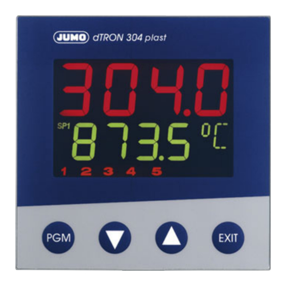
5 Operation 5.1 Displays and controls EXIT 7-segment display (factory setting: process value) four-digit, red, decimal place is configurable (automatic adjustment on display overflow) Active setpoint (factory setting: SP1) SP1, SP2, SP3, SP4 (SP=setpoint); green; 7-segment display (factory setting: setpoint) four-digit, green;... -
Page 26: Level Concept
5 Operation 5.2 Level concept The parameters for making the instrument settings are arranged at different levels. Time-out If no key is pressed for 180 sec, the instrument returns to normal display. v Chapter 6 “Operator level” v Chapter 5.6.1 “Entering programs” (program editor) v Chapter 7 “Parameter level”... -
Page 27: Level Inhibit
5 Operation 5.3 Level inhibit Access to the individual levels can be prevented. Code Operator level, Parameter level Configuration level user level, program editor enabled enabled enabled enabled enabled inhibited enabled inhibited inhibited inhibited inhibited inhibited h Go to code entry with (simultaneously for >5sec). -
Page 28: Entries And Operator Prompting
5 Operation 5.4 Entries and operator prompting Entering values When entries are made within the levels, the parameter symbol is shown in the lower display. Select parameter Alter parameter I I I I I I I I I I I I I h Select parameter with h Change to entry mode with (lower display blinks!) -
Page 29: Fixed-Setpoint Controller (Ex-Factory)
5 Operation 5.5 Fixed-setpoint controller (ex-factory) Normal display Manual mode Altering the In normal display: setpoint h Alter the present setpoint with (the value is accepted automatically) Manual mode In manual mode, the controller output can be altered by hand. h Change to manual mode with (>... -
Page 30: Program Controller
5 Operation 5.6 Program controller Condition as The instrument must be configured as a program controller/generator. Furthermore, a delivered program must be entered beforehand, to operate the instrument as a program controller/generator. 5.6.1 Entering programs Function A setpoint profile can be implemented with a maximum of 8 program segments. Entry on the The instrument must be configured as a program controller/generator. - Page 31 5 Operation The program segments (up to eight) are defined by the segment setpoint and the seg- ment time. I I I I I I I I I I I I I I I I I I I I I I I I I I I I I I I I I I I I I I I I I I I I I I I I I I I I Entry through...
-
Page 32: Operation
5 Operation 5.6.2 Operation Normal display Program is running Altering the setpoint Program pause Normal display No program run in normal display, the controller controls to the selected setpoint. Altering the From normal display: setpoint h Change to setpoint input with h Alter the present setpoint with (the value is accepted automatically) Starting the... -
Page 33: Shifting The Program Profile
5 Operation 5.6.3 Shifting the program profile The function “External setpoint with correction” can be used to shift the program profile upwards or downwards (configurable through the setup program only). The external setpoint is defined via an analog signal. v Chapter 8.2 “Controller “Cntr””... - Page 34 5 Operation...
-
Page 35: Operator Level
6 Operator level Access Process data The four setpoints are displayed and edited here, and additional process variables are shown in accordance with the configuration. Symbol Meaning Setpoint 1 (editable) Setpoint 2 (editable) Setpoint 3 (editable) Setpoint 4 (editable) SP r Ramp setpoint (only if configured) InP1 Measurement of analog input 1... - Page 36 6 Operator level Definition of the program times (1) Program run time (3) Segment run time (2) Residual program time (4) Residual segment time...
-
Page 37: Parameter Level
7 Parameter level General Two parameter sets (PAr1 and PAr2) can be stored. Access The level can be inhibited. Applications - Parameter set switching via binary function v Chapter 8.6 “Binary functions “binF”” - Allocating parameter sets to program segments (only through the setup program) v Program editor / Program Example Setting a 2-state controller with PI action:... - Page 38 7 Parameter level PAr1 ( PAr2 ) PArA Display Value range Factory Description setting Proportional PB 1 0…9999 Size of the proportional band band Pb 2 0…9999 The gain of the controller decreases with increasing proportional band. With Pb 1,2 = 0 the controller structure is ineffective (limit comparator response).
-
Page 39: Configuration
8 Configuration General The following applies to the representation of parameters and functions at the configuration level: The parameter is not displayed or can not be selected if - the equipment level does not permit the function assigned to the parameter. Example: Analog output 2 can not be configured if analog output 2 is not implemented in the instrument. - Page 40 8 Configuration Analog selector With some parameters, you can choose from a series of analog values. To provide you with an overview, this selection is listed below. 0 no function 21 program run time in sec 1 analog input 1 22 residual program time in sec 2 analog input 2 23 segment run time in sec...
-
Page 41: Analog Inputs "Inp
8 Configuration 8.1 Analog inputs “InP” InP: Analog input Configuration Analog inputs Depending on the instrument version, up to two analog inputs are available. Controller Generator Limit comparators Outputs Binary functions Display Timer Interfaces InP1 Analog input 1 InP2 Analog input 2 Symbol Value/selection Description Sensor type... - Page 42 8 Configuration InP1 Analog input 1 InP2 Analog input 2 Symbol Value/selection Description Measurement offset O F F S -1999… 0… +9999 The measurement offset is used to correct a measured value by a certain amount upwards or downwards. Examples: Measured Displayed value...
- Page 43 8 Configuration InP1 Analog input 1 InP2 Analog input 2 Symbol Value/selection Description Heater current H E A t No function monitoring (output) 1…10 Binary output 1—10 (controller output) The heater current is measured via a current transformer with standard signal output and can be monitored by linking analog output 2 to limit comparator 1.
-
Page 44: Customized Fine Tuning
8 Configuration 8.1.1 Customized fine tuning Activate FtS and Ex-factory, both parameters are not visible at the device and have to be activated first. FtE with setup h Connect the device to the PC and start the setup program program h Establisch a connection to the device h Make a double click on Undocumented parameters h Click on check box at Parameter 17 (a tick shall appear) - Page 45 8 Configuration Example The temperature inside an oven is measured with a resistance thermometer and displayed on a device. The reading on the device deviates from the actual temperature as a result of the sensor temperature drifting. At 20°C the device reads 15°C, at 80°C it shows 70°C (exaggerated example for better understanding).
-
Page 46: Controller "Cntr
8 Configuration 8.2 Controller “Cntr” Cntr: Controller Configuration Analog inputs The following are set here: controller type, input variables of the controller, the setpoint Controller limits, conditions for manual mode and the presettings for self-tuning (self- Generator optimization). Limit comparators Outputs Binary functions Display... - Page 47 8 Configuration Symbol Value/selection Description Inputs Controller process (analog selector) Defines the source for the process value of the control value Analog inp. 1 channel. External setpoint (analog selector) Activates the external setpoint input and defines the source switched off for the external setpoint.
- Page 48 8 Configuration Analog selector 0 no function 21 program run time in sec 1 analog input 1 22 residual program time in sec 2 analog input 2 23 segment run time in sec 3 process value 24 residual segment time in sec 4 present setpoint 25 timer run time for timer 1 in sec 5 ramp end value...
- Page 49 8 Configuration Control loop This function is used to monitor the approach behavior when a system starts up and monitoring after setpoint step changes. An alarm is triggered if the process value does not respond to the setpoint signals in accordance with the parameters. The change of the process value in response to setpoint changes is checked.
- Page 50 8 Configuration If the process value does not move outside the adjustable monitoring band toLC within this period, then an alarm signal is generated. The alarm signal is maintained as long as the maximum output level is being produced and the process value is still within the monitoring band.
- Page 51 8 Configuration Output level Output level monitoring checks whether the output level remains within defined limits monitoring (the monitoring band) about an average value when it has settled. The settled state is defined by the control difference band diFb about the process value. If the process value moves outside the monitoring band toLy, then an alarm signal is generated.
- Page 52 8 Configuration The correct operation of the output level monitoring requires sensible dimensioning of the parameters that are used for the determination of the average output level. Control difference band diFb The control difference band about the process value defines the settled state. It should be so dimensioned that there are no excursions outside the band in normal operation.
- Page 53 8 Configuration Boost function In order to move out tools during the production process, the zone temperature can be raised by an adjustable value through a binary function (factory setting: Binary input 1 (key)) for an adjustable time. SP1 - setpoint 1 (in the user level “USEr”) t1 - time for Timer 1 (see “Timer “tFct””...
-
Page 54: Generator "Pro
8 Configuration 8.3 Generator “Pro” Pro: (Program) Generator Configuration Analog inputs The basic function of the instrument is defined here. The instrument can be operated Controller as a fixed-setpoint controller with or without a ramp function, or warm-up ramp for Generator hot-channel equipment, program controller or program generator. - Page 55 8 Configuration Symbol Value/selection Description Unit of slope U n i t Ramp function Program °C/min mm:ss °C/hour hh:mm °C/day dd:hh s=seconds; m=minutes; h=hours;d=days Unit of ramp slope in °C per time unit, or format of segment times for program controller/generator. Ramp slope 0…9999 Value of slope for ramp function...
- Page 56 8 Configuration Warm-up ramp The warm-up ramp for hot-channel equipment is used, for example, for the gentle for hot-channel operation of ceramic heater elements. Damage can be avoided by allowing moisture equipment to evaporate slowly from the hygroscopic heater elements during the warm-up phase —...
-
Page 57: Limit Comparators "Lc
8 Configuration 8.4 Limit comparators “LC” LC: Limit comparator Configuration Analog inputs Limit comparators (threshold monitors, limit contacts) can be used to monitor an input Controller variable (process value for the limit comparator) against a fixed limit or another Generator variable (the setpoint for the limit comparator). - Page 58 8 Configuration In the case of the limit comparator functions lk7 and lk8, the measurement that is set is monitored with respect to a fixed value AL. Hysteresis function asymmetrical, left symmetrical asymmetrical, right Limit comparator 1 Limit comparator 2 Limit comparator 3 Limit comparator 4 Symbol Value/selection...
- Page 59 8 Configuration Limit comparator 1 Limit comparator 2 Limit comparator 3 Limit comparator 4 Symbol Value/selection Description Action/ AcrA absolute/off range response relative/off absolute/on relative/on Action: Defines the switching action of the limit comparators on a setpoint change or power-on. absolute: At the time of alteration, the limit comparator acts according to its function.
- Page 60 8 Configuration Limit comparator 1 Limit comparator 2 Limit comparator 3 Limit comparator 4 Symbol Value/selection Description Acknowledgement Acn L no acknowledgement acknowledgement; only with inactive limit comparator acknowledgement; always possible For settings with acknowledgement, the limit comparator is latching, which means it remains ON, even when the switch- on condition is no longer present.
-
Page 61: Outputs "Outp
8 Configuration 8.5 Outputs “OutP” OutP: Outputs Configuration Analog inputs Configuration of the instrument outputs are subdivided into analog outputs (OutA; Controller max. 2) and binary outputs (OutL; max. 9). Binary outputs are relay, solid-state relay Generator and logic outputs. Display and numbering of the outputs depends on the assignment Limit comparators of the option slots. - Page 62 8 Configuration 0utL Binary outputs Symbol Value/selection Description Binary output 1 0ut1 no function Controller output 1 (ex-factory with Out1) Controller output 2 Binary input 1 Binary input 2 Binary output 10 0ut0 Binary input 3 Binary input 4 Binary input 5 Binary input 6 Binary input 7 Binary input 8...
- Page 63 8 Configuration 0utA 0ut5 Analog outputs Output 5 0ut6 Output 6 0ut7 Output 7 Symbol Value/selection Description Function (analog selector) Function of the output F n c t switched off Type of signal S iG n Physical output signal 0 — 10V 2 —...
-
Page 64: Binary Functions "Binf
8 Configuration 8.6 Binary functions “binF” binF: Binary functions Configuration Analog inputs Functions are assigned here to the binary signals of the binary inputs and limit Controller comparators. Generator In addition, the functions for control contacts, tolerance limit signal and program end Limit comparators signal are defined for program controllers/generators. - Page 65 8 Configuration Symbol Value/selection Description Binary input 1 no function b in 1 Start self-tuning Cancel self-tuning Change to manual mode Binary input 8 b in 8 Controller off (controller outputs are switched off) Inhibit manual mode Limit comparator 1 Hold ramp Cancel ramp Setpoint changeover...
- Page 66 8 Configuration In order to switch between the four possible setpoints, two binary functions must be configured to “setpoint switching”. The states of the two binary functions are designated Z1 and Z2 and switch the setpoints over as shown in the table below: Setpoint Setpoint 1 Setpoint 2...
- Page 67 8 Configuration Depending on the further configuration, the following diagram applies: An exception to this is the configuration for a program controller with external setpoint input, with or without correction. Setpoint 2 is the program setpoint in this case. Reduction For cleaning tools, and for changing colors during the production process, the zone function temperature can be reduced through the binary function “Setpoint switching”...
-
Page 68: Display "Disp
8 Configuration 8.7 Display “diSP” diSP: Display Configuration Analog inputs The values displayed can be matched to the existing requirements. Controller Furthermore, time-out and level inhibit can be configured here. Generator Limit comparators Outputs Binary functions Display Timer Interfaces Symbol Value/selection Description General Upper display... - Page 69 8 Configuration Analog selector 0 no function 21 program run time in sec 1 analog input 1 22 residual program time in sec 2 analog input 2 23 segment run time in sec 3 process value 24 residual segment time in sec 4 present setpoint 25 timer run time for timer 1 in sec 5 ramp end value...
-
Page 70: Timer "Tfct
8 Configuration 8.8 Timer “tFct” tFct: Timer function Configuration Analog inputs Time-dependent control actions can be carried out with the help of the timer. The Controller timer signal (timer 1+ 2) shows whether the timer is active. It can be output via the Generator binary outputs or processed internally. -
Page 71: Interfaces "Intf
8 Configuration 8.9 Interfaces “IntF” Configuration Configuration IntF: Interfaces Analog inputs Controller The interface parameters must be configured for the RS422/485 or current interface, Generator or the Profibus-DP interface, in order to communicate with PCs, bus systems and Limit comparators peripheral devices. - Page 72 8 Configuration Modbus master The instrument can be used as an autonomous master in a Modbus system. It is then possible to send data to all other devices (slaves) in the Modbus system by pressing a key or using a binary function. The slaves must all be devices of the same type. Slave Slave Master...
-
Page 73: Tuning (Optimization)
9 Tuning (optimization) 9.1 Self-tuning (self-optimization) Oscillation Self-tuning (self-optimization, SO) establishes the optimum controller parameters for a method PID or PI controller. Depending on the controller type, the following controller parameters can be defined: Reset time (rt), derivative time (dt), proportional band (Pb), cycle time (Cy), filter time constant (dF) The controller selects one of two procedures (a or b), depending on the size of the control deviation:... - Page 74 9 Tuning (optimization) With output type “solid-state”, the cycle time during self-tuning is reduced to 8 x the sampling cycle time. With the “relay” output type, care has to be taken that the process value is not influenced by the cycle time, since otherwise tuning can not be completed successfully.
- Page 75 Chapter 8.2 “Controller “Cntr”” For a device configured as program controller, the autotuning can only be started if no program is running (normal display). In case of problems, you may find further information at www.jumo.net (Support/FAQ). h Cancel with...
-
Page 76: Checking The Tuning
9 Tuning (optimization) 9.2 Checking the tuning The optimum adaptation of the controller to the process can be checked by recording the approach phase (e.g. with Startup) with the control loop closed. The diagrams below indicate possible maladjustments and how these can be corrected. The control response of a third-order control loop for a PID controller is shown as an example. -
Page 77: Extra Codes
10 Extra codes 10.1 Math and logic module The setup program can be used to implement two mathematical calculations or logical combinations of various signals and process variables from the controller in a formula. With math formulae, the calculated result is presented through the two signals “Math 1”... - Page 78 10 Extra codes Humidity control A psychrometric humidity sensor is used to determine relative humidity, through the mathematical combination of wet bulb and dry bulb temperatures. relative humidity: (E1, E2) = analog input 1 Math (dry bulb temperature) Upper analog input display (wet bulb temperature...
-
Page 79: Retrofitting Of Modules
11 Retrofitting of modules Safety notes Retrofitting must only be carried out by qualified professional persons. The modules can be damaged by electrostatic discharge. So avoid electrostatic charge during fitting and removal. Carry out retrofitting on a workbench that is earthed. h Identify the module by the Sales. - Page 80 11 Retrofitting of modules h Press together the knurled surfaces Removing the on the front panel and pull out the controller controller module. module h Select the slot for the option Retrofitting of modules (Observe the restrictions for Type 703045! (see connection diagram)) Type 703045 Type 703046/48 On Type 703045, relays...
-
Page 81: Appendix
12 Appendix 12.1 Technical data Thermocouple input Designation Measuring range Measuring Ambient accuracy temperature error ≤0.25% Fe-Con L -200 to + 900°C 100 ppm /°C ≤0.25% Fe-Con J EN 60 584 -200 to +1200°C 100 ppm /°C ≤0.25% Cu-Con U -200 to + 600°C 100 ppm /°C ≤0.25%... - Page 82 12 Appendix Measuring circuit monitoring In the event of a fault, the outputs move to a defined (configurable) status. Sensor Overrange / Probe or lead short-circuit Probe or lead break underrange Thermocouple • • Resistance thermometer • • • Voltage 2 —...
- Page 83 12 Appendix Electrical data Supply voltage (switchmode PSU) 110 — 240V AC -15/+10%, 48 — 63Hz 20—30V AC/DC, 48—63Hz Electrical safety Type 703045: to EN 61010, Part 1 Type 703046/48: to EN 60730 Overvoltage category III, pollution degree 2 Power consumption 13VA max.
- Page 84 12 Appendix Approvals/marks of conformity Mark of Testing laboratory Certificates/certification Test basis valid for conformity numbers c UL us Underwriters Laboratories E 201387 UL 61010-1 all types CAN/CSA-C22.2 No. 61010-1...
-
Page 85: Alarm Messages
12 Appendix 12.2 Alarm messages Display Cause Fault removal test/repair/replace -1999 Underrange for the value being Check that the connected probe com- displayed. plies with the configured sensor type and (blinking!) linearization 9 9 9 9 Overrange for the value being Check the probe connection and the ter- displayed. - Page 86 12 Appendix...
-
Page 87: Index
13 Index Hot-channel 56 Humidity control 78 Access code 39 Accessories 10 Acknowledgement 60 Analog input 41 Installation notes 15 Analog marker 71 Interface 71 Analog selector 40 Level concept 26 Baud rate 71 Level inhibit 27 Binary functions 64 Limit comparator 57 Binary marker 71 Limit comparator functions 57... - Page 88 13 Index Timer 70 setting 70 Safety notes 79 Times, entering 28 Sampling cycle time 43 Tolerance band 55 Scope of delivery 10 Tuning (optimization) 76 Self-tuning (self-optimization) 47 Type designation 9 Sensor type 41 Setpoint 35 external 47 Setpoint limits 46 Unit 55 Setpoint switching 65 temperature 43...
- Page 90 Overview of the configuration level Sensor type InP1 SEnS Page 41 InP2 Linearization OFFS Measurement offset Display start Display end Filter time constant Fine tuning start value Fine tuning end value Heater current monitoring HEAt InP12 Unit Temperature unit CYcL Sampling cycle time Cntr CtYP...
- Page 91 tFct Fnct Function Page 70 tF2 Timer time toLt Tolerance limit IntF ProF Prot Protocol Page 71 Device address AnAP Analog marker binP Binary marker Protocol r422 Prot Bdrt Baud rate Data format Device address...
- Page 92 JUMO GmbH & Co. KG JUMO Instrument Co. Ltd. JUMO Process Control, Inc. Street address: JUMO House 8 Technology Boulevard Moritz-Juchheim-Straße 1 Temple Bank, Riverway Canastota, NY 13032, USA 36039 Fulda, Germany Harlow, Essex CM20 2DY, UK Phone: 315-697-JUMO Delivery address:...
Need help?
Do you have a question about the dTRON 316 plast and is the answer not in the manual?
Questions and answers