
Related Manuals for Leister NOVOLAS Basic AT


Summary of Contents for Leister NOVOLAS Basic AT
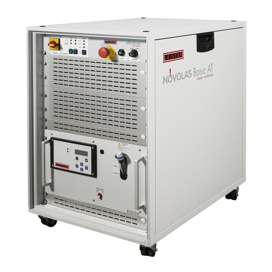
- Page 1 System Manual NOVOLAS Basic AT Version 2.1 09/2010 Subject to change without notice Änderungen vorbehalten...
- Page 2 Leister reserves the right to update the content of this manual at any time without prior notification. Copyright This document may not be copied. All rights reserved, including those of translation, reprinting and reproduction of the document or parts thereof. No part of the document may be reproduced or distributed without the permission of the author (or the board of management), in any form, including for purposes of conference, presentation and advertising.
-
Page 3: Table Of Contents
6.3 Operation modes and modifications of the Basic AT 2.1.1 Laser Safety Class 6.3.1 Current Setting Mode 2.2 Safety of the NOVOLAS Basic AT system 6.3.2 Activating the Laser (Register 3) 2.2.1 Hazards from Laser Light 6.3.3 On-Off Temperature Regulator (Register 1 and 6) 48 2.2.2 Hazards from electrical energy... -
Page 4: General
• Maintenance The meaning of the symbols and Warning labels used on the NOVOLAS Basic AT system may be found in chapter 9 of this manual. Checklists for installation found in Chapter 5.5 , for maintenance in chapter Maintenance of this Manual. -
Page 5: Proper Use
09/2010 Proper Use The NOVOLAS Basic AT system may not be operated as a standalone system. It must be integrated into equipment, which complies with the applicable directives and standards. The Basic AT may only brought in to service after a laser warning lamp or other warning device complying with EN60825-1 has been installed. -
Page 6: Organizational Measures
No alterations should be carried out on the NOVOLAS Basic AT without prior consultation and written approval from Leister Process Technologies. The safety of the NOVOLAS Basic AT is compromised at best as a result of modifications. The user is exclusively liable for all damages arising from alterations, which are not expressly approved by Leister Process Technologies. -
Page 7: Safety Instructions
Only when this is ensured, the NOVOLAS Basic AT may be put into operation as a component of the entire equipment. Pay special attention to the hazards arising from the NOVOLAS Basic AT itself, as described in this manual. -
Page 8: Laser Safety Class
Below, several standards are listed, which could be relevant for the use of the NOVOLAS Basic AT and/or of the equipment in which the Basic AT is integrated. The list is purely informative. Leister Process Technologies accepts no responsibility for the completeness of this list. -
Page 9: Hazards From Laser Light
09/2010 2.2.1 Hazards from Laser Light Laser diodes, as fitted in the NOVOLAS Basic AT, generate intense radiation in the invisible, near infrared spectral range (800 – 1000 nm). Direct laser light and/or scattered radiation can be hazardous to eyes and skin. - Page 10 • Implement the necessary protective measures in the danger zone of the NOVOLAS Basic AT in order to avoid exposure of eyes or skin from direct or scattered radiation and to warn of hazards (also see the standard EN60825- •...
-
Page 11: Hazards From Electrical Energy
09/2010 2.2.2 Hazards from electrical energy Shut down the NOVOLAS Basic AT immediately, if there are faults in the electric energy supply. Regularly inspect the electrical equipment of the NOVOLAS Basic AT. Defects, e.g. loose connections or damaged cables, must be rectified without delay. -
Page 12: Hazards From Gases Or Vapours
Low voltage hazard points • The NOVOLAS Basic AT conforms to Safety Class 1 and it is imperative that it is connected to a continuous earth connection. The NOVOLAS Basic AT earth leads are connected to the mains connection terminals inside the supply unit and are marked with the appropriate symbol. -
Page 13: Novolas Basic At Safety Devices
(On request, this can be adapted by Leister Service Personal). After an emergency stop the laser safety stop has to be released and the reset button has to be pushed in order to start the system again. -
Page 14: System Description
System Description Hardware Overview The NOVOLAS Basic AT is based on the Leister NOVOLAS AT platform. This platform consists of a variety and growing number of modules, which can be easily combined to build a customized laser systems optimized for plastic welding applications. The figure below represents the structure of the NOVOLAS Basic AT. - Page 15 Version 2.1 NOVOLAS Basic AT 09/2010 NOVOLAS BASIC AT Control Unit Novolas Basic AT Laser unit #n, Linebeam Linebeam (haz lineal) Laser unit #A, Linebeam Linebeam Cabezal optico Optics Módulo láser Laser module Current Source (Fuente de alimentación) Current Source...
- Page 16 The System Master is responsible for the configuration and integrity checks during setup and the surveillance of the system during operation. The NOVOLAS Basic AT control module contains the 24V DC power supply, the emergency stop circuitry, the Ethernet switch, control switches and other common parts to make the modules work.
-
Page 17: System States
• System Error When main power is applied to the NOVOLAS Basic AT the system is in not started state. After about 45 seconds, the System Master starts its programs and the system is set in initialization state. The System Master communicates with the cooler and waits until the cooling liquid temperature will be lower than 23°... -
Page 18: Interfaces
NOVOLAS Basic AT Version 2.1 09/2010 Interfaces Overview The NOVOLAS Basic AT provides electrical interfaces to • start the system • stop the system (Emergency Stop) • unblock the interlock of the laser modules, • set laser module current •... -
Page 19: Terminal Block (X90, X91-94)
4.2.1 Common Control Interface (X 90) Emergency Stop and Laser Enable The NOVOLAS Basic AT includes a common safety gate, which builds the emergency-stop control unit for all installed laser units. This control unit provides two independent electrical channels that will interrupt the power supply of the current sources when the emergency stop is active. -
Page 20: Individual Laser Unit Control Interface (X91-X94)
NOVOLAS Basic AT Version 2.1 09/2010 Reset: Terminals 1/2 To start the system, the terminals 1 and 2 have to be closed with a potential free switch for at least 100 ms. Only use external potential free switches (dry contacts). -
Page 21: Customer I/O
Version 2.1 NOVOLAS Basic AT 09/2010 Customer I/O This module is used to build the interface to the surrounding customer system (e.g. PLC). It provides inputs to set the current and to switch the laser current on and off. It signals the state of the system and the actually flowing laser current. -
Page 22: Digital Outputs (X15)
NOVOLAS Basic AT Version 2.1 09/2010 The guiding laser off signal will disable any guiding laser if this input is active. This may help avoiding life time issues of this part, if welding operation is short compared to machine on-time. -
Page 23: Interface Pin Assignements X15, Including Good/Bad Evaluation
Version 2.1 NOVOLAS Basic AT 09/2010 4.3.3 Interface pin assignements X15, including good/bad evaluation As an alternative, the good/bad evaluation signals may be optained from the digital output X15 of the CustomerI/O. The results of the good/bad evaluation of the DataManager are in this case obtained form the pins X15.4-X15.6. -
Page 24: Analogue Inputs (X16)
NOVOLAS Basic AT Version 2.1 09/2010 4.3.4 Analogue Inputs (X16) General specification: • Voltage range 0 to 10 Volt • Impedance app. 50 kOhm • Maximum voltage 35 Volt • Attention! Common reference potential with analogue outputs and serial ports... -
Page 25: Serial Interface Rs232 (X18)
Version 2.1 NOVOLAS Basic AT 09/2010 4.3.6 Serial Interface RS232 (X18) General specification: • RS232 standard compliant signals • connection and application settings depends on the installed software. • Attention! Common reference potential with analogue inputs and serial ports Terminal... -
Page 26: External Laser Interface (X80/81, Coolant)
NOVOLAS Basic AT Version 2.1 09/2010 External Laser Interface (X80/81, Coolant) X80. - X80. + coolant X81 Figure 8: Interfaces for external laser modules Some AT versions e.g. such with line beam lasers use external laser diodes. This versions possess an interface for high current, cooling circuit and interlock. This interface is located at the back side of the 19”... -
Page 27: Interlock To Laser Module (X81)
Version 2.1 NOVOLAS Basic AT 09/2010 4.4.2 Interlock To Laser Module (X81) The interlock of the external laser module must be connected to this plug. Within the cabinet the contacts are directly wired to the corresponding terminals of X9x (X91- X94 depending on the laser unit). -
Page 28: Installation
Local transportation is defined as moving the NOVOLAS Basic AT within a building (Temperatures above 0°C). The NOVOLAS Basic AT is fitted with 4 casters. For transport, it can be pushed on plane surfaces. For longer distances use appropriate devices such as a fork-lift to transport the NOVOLAS Basic AT. -
Page 29: Long-Distance Transportation
• ship • airplane Use the original packaging for the NOVOLAS Basic AT or make sure to package the system such as to protect it from mechanical damage during the transport. Prepare the NOVOLAS Basic AT system as follows: •... -
Page 30: Conditions For Setting-Up
The temperature and humidity of the location must comply with the specified values in the technical data. Conditions for setting-up All information necessary for the setting-up and connecting the NOVOLAS Basic AT is given in the technical data. Furthermore, you will find •... - Page 31 Version 2.1 NOVOLAS Basic AT 09/2010 Figure 9: NOVOLAS Basic AT: System Overview System Master AT Customer I/O AT Fiber connector Laser Module Exhaust Air Chiller Figure 10: Basic AT - Side View Installation...
- Page 32 NOVOLAS Basic AT Version 2.1 09/2010 Mains Connection and overvoltage protection/ Netzanschluss und Überspannungsschutz Customer I/O AT Terminals X90, Filter X91 etc. Fuses F1-F4 Sicherungen System Master AT Safety Relays/ Sicherheitsrelais 24V Supply/ Ethernet Switch 24V Versorgung Figure 11: Basic AT- View into control slot...
- Page 33 Figure 12: Basic AT Control Rack with POE Injector (optional) Step General Installation Remarks Select a suitable location for the NOVOLAS Basic AT. A Prepare AC power suitable location will provide sufficient fresh air to the connection system and enables a free escape of the exhaust air on the back side.
- Page 34 120 W, 200 W fiber coupled laser modules: Install Must be dry, clean and purge air supply to the NOVOLAS Basic AT. completely oil-free to avoid condensation. Tube has an external diameter of 6 mm.
- Page 35 Version 2.1 NOVOLAS Basic AT 09/2010 Step Processing optics Remark Mount processing optics or laser head. Module Manual of the according optic Optical fiber connector must be tightly connected. Clean the exit lens of the processing optics if required. For optics equipped with pyrometer:...
- Page 36 Connect the NOVOLAS Basic AT system to the electrical Check whether the voltage supply. agrees with the indication on the type plate.
-
Page 37: Time Scheme For Typical Integration
Version 2.1 NOVOLAS Basic AT 09/2010 5.5.1 Time scheme for typical Integration Configuration Procedure Cmode: 2 1. Interlock closed Rmode: 0 2. Interlock Test finished Gmode: 3 3. Gate active Activation: 2 4. Ready signal active Keyswitch: Enable 5. Trigger Status change... -
Page 38: Typical Wiring Of A Basic At With An External Laser Unit (I.e. Linebeam)
NOVOLAS Basic AT Version 2.1 09/2010 5.5.2 Typical wiring of a Basic AT with an external laser unit (I.e. Linebeam) AT Electrical Interface Input Output Start, Reset X90.1 X90.7 Warning close min. 100ms laser system X90.2 X90.8 to start system powered, X90.9... -
Page 39: Operation
The system can then be started by first switching the Laser Enable key switch to “ON” and pressing the blue Reset button on the front panel of the NOVOLAS Basic AT. Alternatively, the Reset may be activated by shorting for 100 to 500 ms terminal 1 and 2 on the terminal block with a potential free switch. -
Page 40: Configuring The Novolas Basic At
Version 2.1 09/2010 Configuring the NOVOLAS Basic AT The RS232 interface allows communication to the NOVOLAS Basic AT system in order to set operation modes and parameters or to obtain status information. Communication parameter settings: 19200 Bauds, 8 data bits, no parity, one stop bit The following ASCII protocol is used for the RS232 interface: All commands are initiated with a colon “:”... - Page 41 Version 2.1 NOVOLAS Basic AT 09/2010 The table below gives an overview of the available registers. The individual meaning is described in the following chapters Register Name Function Units Value range Index Read / write registers CMode Sets the way the...
- Page 42 NOVOLAS Basic AT Version 2.1 09/2010 Register Name Function Units Value range Index TSet Target temperature - This sets the target temperature for corresponding closed loop control modes. The unit depends on bit 0 of register 1. ISet Sets the current if 0.1A 0-2000, preset 0...
- Page 43 Version 2.1 NOVOLAS Basic AT 09/2010 Register Name Function Units Value range Index Actual current 0.1A 0-4095, current capability depends on emitted by the current source module. current source With the Air Cooled Laser Module, the unit is 0.01A) T_Pyro...
- Page 44 NOVOLAS Basic AT Version 2.1 09/2010 Register Name Function Units Value range Index INTERLOCK: Common error in interlock testing. Restart. Replace module if necessary (bei Leister service) 1024 LASERVOLTMAX: Laser voltage exceeded maximum. Restart. Replace module if necessary (bei Leister service)
- Page 45 Version 2.1 NOVOLAS Basic AT 09/2010 Module interlock error TEMP_2: Error Temperature 2 when using an air TEMP_3: Error Temperature 3 cooled laser TEMP_4: Error Temperature 4 module (corresponds to CONTROLTEMP: Temperature Error the messages as in Laser diode provided in register...
-
Page 46: Operation Modes And Modifications Of The Basic At
Error. Interlock is in error state. Operation modes and modifications of the Basic AT The behavior of the NOVOLAS Basic AT depends on the operation mode. For laser emission the current setting must be higher than the laser diode threshold and the current source must be enabled. - Page 47 Version 2.1 NOVOLAS Basic AT 09/2010 Digital Current Set Mode (Register 0=0) In Digital Current Set Mode the current can be set by writing into register 7. The value 100 corresponds to 10A current. For the air cooled laser module, the value 100 corresponds to 1A.
-
Page 48: Activating The Laser (Register 3)
NOVOLAS Basic AT Version 2.1 09/2010 6.3.2 Activating the Laser (Register 3) The above setting influences the current setting. They will not activate the laser or start a profile, however. Enabling of the laser will depend on the values in registers 2 and 3. -
Page 49: Switching Off The Novolas Basic At
NOVOLAS Basic AT 09/2010 Switching off the NOVOLAS Basic AT Make sure that the laser-unit's interlocks are opened and that the analogue or digital current set is set to 0. Switch off the system by switching off the mains switch. -
Page 50: Diagnostics Leds
NOVOLAS Basic AT Version 2.1 09/2010 Diagnostics LEDs Most AT System modules are equipped with two diagnostic lamps L1+ L2 for system diagnostics. . Each lamp consists of two LEDs, each with green and red colour. If the red and green is activated at the same time, the colour impression is yellowish. To achieve a correct analysis, the lamp has to be viewed under 90°... -
Page 51: Service And Troubleshooting
USB memory stick into the USB interface on the front side of the NOVOLAS Basic AT and leave it plugged in for at least 60s. Please copy the logfile “logfile.log…” in form of a zip-file onto the memory stick. Send the stick to tcs.laser@leister.com and ask for immediate support. - Page 52 Cooler: Water flow To low water flow rate Check cooling circuit. Replace water filter cartridge. If this error occurs more frequently than every 6 months, please contact Leister service personal. System does not start up Power supply. Assure and control power supplies.
-
Page 53: Laser Module Faults
Version 2.1 NOVOLAS Basic AT 09/2010 Laser Module Faults Error Cause Measures No aiming beam and no Broken fiber optic cable Replace fiber optic cable or low weld laser Damaged laser module No weld laser but Interlock circuit not closed... -
Page 54: Maintenance
NOVOLAS Basic AT Version 2.1 09/2010 Maintenance The owner of the NOVOLAS Basic AT is responsible for having the proper maintenance carried out. • Shut down the system and protect against unauthorized use when you carry out work on the NOVOLAS Basic AT. -
Page 55: Spare Parts
Version 2.1 NOVOLAS Basic AT 09/2010 Spare parts You must obtain all spare parts, including those not listed, from Leister Process Technologies. Standard small parts, such as screws etc. can also be obtained from other sources. Article No. Part 131.601 Particulate filter element 120.799... -
Page 56: Warning Notices And Abbreviations
(also see the standard EN60825-1) This symbol warns of dangerous electrical voltages. Shut down the NOVOLAS Basic AT system before commencing repair work, protect against unauthorized operation and disconnect the NOVOLAS Basic AT systems mains plug. -
Page 57: Abbreviations And Terms
Operator Person authorized to process work pieces using the NOVOLAS Basic AT Owner Owner and user of the NOVOLAS Basic AT Fitter Person authorized to operate and program the NOVOLAS Basic AT. Manual workstation = Supply (OEM) and work cell... -
Page 58: Labels On The Novolas Basic At
NOVOLAS Basic AT Version 2.1 09/2010 Labels on the NOVOLAS Basic AT Label Warning Location Warning laser On the rear of the Radiation system housing and all laser heads, laser modules and optic modules Warning of hazardous On the rear of the... - Page 59 Auf der Rückseite des Laser unit B : Gehäuses Laser unit C : Laser unit D: 230 VAC ± 10% 50/60 Hz 16 A 3600 W Made in Switzerland LEISTER Process Technologies, CH -6060 Sarnen Service contact: tcs.laser@leister.com Warning Notices and Abbreviations...
-
Page 60: Technical Data
NOVOLAS Basic AT Version 2.1 09/2010 Technical Data 10.1 Installation data Before switching on, ensure that the machine is supplied with the correct mains voltage. Voltage 230 VAC ± 10%, (200VAC ± 10% optional) Frequency 50 Hz ± 1% or 60 Hz ± 1% Max. -
Page 61: Laser Power Supply And Laser Module
(conductivity: 5-10 µS, filtered < 20 µm) Capacity approx. 3.5 liter (total incl. pump, filter and tubes) Filter unit 20 µm Water tube use only the tubes supplied by Leister! 10.6 Conductor cross-sections Wires mm2 Remark 0.25 Analog and digital signals such as EMERGENCY STOP, Reset etc. -
Page 62: Notes
NOVOLAS Basic AT Version 2.1 09/2010 Notes Notes...
Need help?
Do you have a question about the NOVOLAS Basic AT and is the answer not in the manual?
Questions and answers