
Related Manuals for Leister VARIMAT 700


Summary of Contents for Leister VARIMAT 700
- Page 1 English VARIMAT 700/500/300 Leister Technologies AG Galileo-Strasse 10 6056 Kaegiswil Switzerland +41 41 662 74 74 leister@leister.com leister.com...
-
Page 2: Table Of Contents
Table of Contents Table of Contents 1. Application Intended use Non-intended use General safety information 2. Technical data 3. Transport 4. Your VARIMAT 700/500/300 4.1 Type plate and identification 4.2 Scope of delivery (standard equipment in the case) 4.3 Overview of device parts 5. Settings on the VARIMAT 700/500/300 5.1 Adjusting the welding nozzles 5.2 Additional weights for increasing the contact pressure weight 5.3 Adjusting the guide bar 5.4 Adjusting the movable transportation axle 5.5 Adjusting the track setting 6. VARIMAT 700/500/300 commissioning 6.1 Work environment and safety 6.2 Operating readiness... - Page 3 10.6 LQS data recording settings (VARIMAT 700) 10.7 Advanced mode settings 10.8 WLAN settings 10.9 Device settings 10.10 Info mode 10.11 Duty info 10.12 General Info 11. VARIMAT 700/500 warning and error messages 12. VARIMAT 700/500 FAQs, causes and measures 13. Operating VARIMAT 300 13.1 Starting the device 13.2 Welding sequence 13.3 Finishing welding 13.4 Switching off the device/Maintenance 14. VARIMAT 300 quick guide 14.1 Switching on/Starting 14.2 Switching off 15. VARIMAT 300 operating unit 15.1 Function buttons 15.2 Digital display 15.3 Display symbols of the status display (Display 34) 15.4 Display symbols for the welding speed (Display 35) 15.5 Display symbols for the welding temperature (Display 36) 15.6 Display symbols for the air volume (Display 37) 15.7 Status LED display 16. Settings and functions of the VARIMAT 300 software ...
-
Page 4: Application
Operating instructions (Translation of the Original User Manual) Congratulations on your purchase of the VARIMAT 700/500/300. You have chosen a first-class hot-air welder. It was developed and produced in accordance with the latest state-of-the-art technology in the plastics-processing sealing sheet industry. It has also been manufactured using high-quality materials. Please always store these operating instructions with the device. VARIMAT 700/500/300 Hot-air welder You can find more information on the VARIMAT 700/500/300 at leister.com 1. Application Intended use The VARIMAT 700/500/300 automatic hot-air welder is designed for professional use on flat roofs. Welding procedures and types of materials ƒ Overlap welding of thermoplastic sealing sheets/elastomer sealing sheets (such as TPO, PVC, ECB, modified EPDM, EVA, FPO, PIB, PMI, PO, PP) ƒ Near-edge welding on the verge (roof parapets and eaves) up to 100 mm. The legal provisions on health protection applicable in the respective country must be observed. Never use the hot-air welder in explosive or readily inflammable surroundings. Maintain sufficient distance from combustible materials or explosive gases at all times. Read the material safety data sheet from the manufacturer of the material and follow that company’s instructions. Be careful not to burn the material during the welding process. Observe general safety instructions [1.3]. Non-intended use Any other use or any use beyond the type of use described is deemed non-intended use. -
Page 5: General Safety Information
1.3 General safety information Please observe the safety instructions provided in the individual chapters of these operating instructions as well as the following safety instructions. Warning Risk of death from electric shock due to dangerous electrical voltage ƒ The device is only to be connected to sockets and extension cables with a protective earth conductor. ƒ Protect the device from moisture and wet conditions. ƒ When used on a construction site, a residual current circuit breaker is mandatory. ƒ Prior to using the device for the first time, check the power cord, the plug, and the extension cable for electrical and mechanical damage. ƒ The device may only be opened by instructed, qualified personnel. Danger of fire and explosion with improper use in the vicinity of flammable materials and explosive gases. ƒ Avoid overheating of the material. ƒ Never place the device near combustible materials and/or explosive gases. ƒ Never place the device close to combustible materials and/or explosive gases while it is running and/ or hot. ƒ Only use the device on fireproof surfaces. Risk of burns due to hot equipment parts and hot air jet ƒ Do not touch the heating tube and nozzle when they are hot. ƒ Always allow the device to cool down first. ƒ Never point the hot air flow at people or animals. Caution ƒ The local supply voltage must match the nominal voltage specified on the device. ƒ Maximum network impedance according to EN 61000-3-11 / UL 499 / CSA C22.2 No 88: Zmax = 0.169 Ω + j 0.106 Ω. In case of doubt, the responsible electricity supply company should be contacted. -
Page 6: Technical Data
2. Technical data VARIMAT VARIMAT VARIMAT VARIMAT VARIMAT VARIMAT 230 V 400 V 230 V 400 V 230 V 400 V Voltage Capacity 3680 5700 3680 5700 3680 5700 Frequency 50/60 °C 100–620 Temperature °F 212–1148 Max. Ambient °C temperature °F Air volume 45–100 m/min 1.0–12 1.0–10 Drive ft/min 3.2–39.4 3.2–32.8... -
Page 7: Transport
3. Transport ƒ Comply with applicable national regulations regarding the carrying or lifting of loads. ƒ For transporting the hot-air welder use the transport box included in the scope of delivery and carry the transport box using the handle provided for the purpose. ƒ The weight of your VARIMAT 700/500/300, including the transport box, is 45.0 kg (37.5 kg without transport box, including 1 weight). ƒ Two persons are required for transporting the machine with the transport box. Fire hazard when transporting while hot ƒ The hot air blower (9) reaches temperatures of 620 °C. ƒ Allow the hot-air blower (9) to cool down sufficiently prior to transport (see Cool Down mode [16.3]). ƒ Never store flammable materials (such as plastic or wood) in the transport box. ƒ Never use the carrying handle (4) on the device or on the transport box for transporting with a crane, as this may cause the unit to fall. ƒ Never lift the hot-air welding machine by the auxiliary weights (3) as there is a risk of the machine falling. To lift up the hot air welder by hand, use the carrying To position the hot air welder, press the guide bar (23, handle (4). 25) and then roll the device in this way into the desired welding position. -
Page 8: Your Varimat 700/500/300
4. Your VARIMAT 700/500/300 4.1 Type plate and identification The model and serial number are indicated on your device’s name plate (18). Transfer this information to your operating instructions; in the event of any inquiries to our country subsidiary or your authorized Leister sales and service partner, please always refer to this information. Model: ....................................Serial no.: ....................................Example: 4.2 Scope of delivery (standard equipment in the case) 1 VARIMAT 700/500/300 device 1 auxiliary weight Guide bar, folded in Upper handle 5 m cable 1 wire brush 2 welding protection plates 1 nozzle adjustment gauge 1 Torx T20 screwdriver length 250 mm 1 safety Instructions 1 Quick Reference Guide 1 hexagonal pin spanner, size 4... -
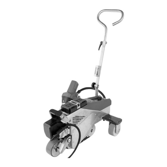
Page 9: Overview Of Device Parts
4.3 Overview of device parts 1. Control panel 16. Track guide roller 2. Housing 17. Swivel mechanism 3. Auxiliary weight 18. Type plate with model designation and series marking 4. Carrying handle 19. Activating sliding transport axis 5. Holder for power cord (with carabiner for hanging) 20. Main switch (On/Off switch) 6. Power cord 21. Movable transport axis 7. Basic weight 22. Locking screw (guide bar) 8. Trailing roller 23. Guide bar, bottom 9. Hot Air Blowers 24. Clamping lever, guide bar, top part 10. Drive roller / contact pressure roller 25. - Page 10 Control panel (1) VARIMAT 700/500 Control panel (1) VARIMAT 300 Actuation of movable transport axis (19), main Type plate (18) switch (20) Hold-down belt (26), deflection roller (27)
-
Page 11: Settings On The Varimat 700/500/300
5. Settings on the VARIMAT 700/500/300 5.1 Adjusting the welding nozzles = 55 mm +/− 2 = 1–2 mm = 1 mm 2 x socket head screws 4 x Torx screws Set dimension “A + B” (2 socket head screws) Set dimension “C” (4 Torx screws) -
Page 12: Additional Weights For Increasing The Contact Pressure Weight
5.2 Additional weights for increasing the contact pressure weight 22 kg 25 kg 28 kg The base weight (7) weighs 13.5 kg and can be removed for transportation. 5.3 Adjusting the guide bar... -
Page 13: Adjusting The Movable Transportation Axle
5.4 Adjusting the movable transportation axle Pos. 1 Pos. 2 Pos. 3 Position 1: End position Basic welds Welding Position 2: Middle position Basic welds Welding Position 3: Welding close to the edge 5.5 Adjusting the track setting 1. Undo the two M6 x 16 cheese-head screws. 2. Set the track with the track setting (15). 3. Check the setting on the track setting indicator (13). 4. Retighten the two M6 x 16 cheese-head screws. Cheese-head screw M6 × 16... -
Page 14: Varimat 700/500/300 Commissioning
6. VARIMAT 700/500/300 commissioning 6.1 Work environment and safety Safety precautions Risk of death from electric shock due to dangerous electrical voltage ƒ The device is only to be connected to sockets and extension cables with a protective earth conductor. ƒ Protect the device from moisture and wet conditions. ƒ When used on a construction site, a residual current circuit breaker is mandatory. ƒ Prior to using the device for the first time, check the power cord, the plug, and the extension cable for electrical and mechanical damage. ƒ The device may only be opened by instructed, qualified personnel. Danger of fire and explosion with improper use in the vicinity of flammable materials and explosive gases. ƒ Avoid overheating of the material. ƒ Never place the device near combustible materials and/or explosive gases. ƒ Never place the device close to combustible materials and/or explosive gases while it is running and/ or hot. ƒ Only use the device on fireproof surfaces. Risk of burns due to hot equipment parts and hot air jet ƒ Do not touch the heating tube and nozzle when they are hot. ƒ Always allow the device to cool down first. ƒ Never point the hot air flow at people or animals. Risk of inadvertently becoming caught and being pulled in due to moving parts ƒ Do not touch any moving parts. ƒ Do not wear loose articles of clothing such as scarves or shawls. ƒ... - Page 15 ƒ The local supply voltage must match the nominal voltage specified on the device. ƒ Maximum network impedance according to EN 61000-3-11 / UL 499 / CSA C22.2 No 88: Zmax = 0.169 Ω + j 0.106 Ω. In case of doubt, the responsible electricity supply company should be contacted. ƒ If the power supply fails, switch off the unit at the main switch and swing the hot air blower into the park position, in order to avoid damage to the hot-air blower. Caution ƒ Comply with national statutory requirements regarding occupational safety (securing personnel or devices). Risk of glare due to the LED light beam ƒ Avoid direct eye contact with the LED light beam. Caution ƒ Only use the device on horizontal and fireproof surfaces. ƒ Comply with applicable national regulations regarding the carrying or lifting of loads. ƒ For transporting the hot-air welder use the transport box included in the scope of delivery and carry the transport box using the handle provided for the purpose. ƒ The weight of your VARIMAT 700/500/300, including the transport box, is 45.0 kg (37.5 kg without transport box, including 1 weight). ƒ Two persons are required for transporting the machine with the transport box.
- Page 16 ƒ Anti-fall protection when working in areas where there is a fall hazard ƒ When welding on roof parapets (parapet, eaves), the hot air welder on the carrying handle (4) must be secured to a stop fixture with horizontal guides (such as rail or rope safety systems) as protection against falling. ƒ With respect to the safety chain, care must be taken to ensure that all of the safety elements (carabiner hooks, ropes) have a minimum load-carrying capacity of 7 kN in every direction that can be anticipated. It is mandatory to use locking carabiners (twist-lock or screw types) to hook the unit. You must properly install and check all connections of the safety chain according to the manufacturer’s specifications. Before each use and after unusual occurrences, the carry- ing handle (4) that is used for fastening the safety rope must be inspected by an individual with expertise in this area. The carrying handle (4) is not permitted to exhibit any cracks, corrosion, notches or other material faults. Secure the additional weights with the additional plates provided (1 per weight). Additional plate...
- Page 17 Caution ƒ Only secure the hot air welding machine by the carrying handle (4). ƒ Never fasten the hot wedge welding machine to single anchoring points which allow ropes to sag. Always set the connection equipment to the shortest length possible in order to eliminate any chance of falling over the edge of the parapet. Caution ƒ The device may fall or drop in an uncontrolled manner due to gravity. The securing point is not designed to withstand the shock-like stress of an abrupt fall. ƒ Please do not hesitate to contact the manufacturer if anything is unclear during installation or operation. Power cord and extension cable ƒ The nominal voltage specified on the device (see Technical data [2]) must match the supply voltage. ƒ The power cord (6) must be able to move freely and must not hinder the user or third parties during work (trip hazard). ƒ The extension cables must be authorized for the utilization site (e.g., outdoors) and be marked accord- ingly. Take the necessary minimum cross-section for extension cables into account as required. On-site generators for power supply When using on-site generators as a power supply, please ensure that the on-site generators are grounded and equipped with residual-current circuit breakers. For the nominal output of the power plants, the formula “1.5–2 × nominal output of the hot-air welder” applies.
-
Page 18: Operating Readiness
6.2 Operating readiness Hang the strain relief of the power supply cord (6) from the power cord holder (5) and then check the basic setting of the welding nozzle (11). See the how-to videos on Leister’s YouTube channel Welding plate 26 10... -
Page 19: Operating Varimat 700/500
7. Operating VARIMAT 700/500 7.1 Starting the device ƒ Once you have prepared the working area and the hot air welder in accordance with the instructions, connect the hot air welder to the supply voltage. ƒ Use the main switch (20) to switch the hot-air welder on. After startup, the Start screen will appear briefly in the display, with the version number of the current software release and the device designation. If the device was allowed to cool down beforehand, this will be followed by a static display of the set values of the most recently used profile (the Basic profile is displayed when the device is first commissioned). The heating is not yet switched on at this stage. ƒ Select the desired welding profile or define the welding parameters individually. ƒ Now switch the heating on with the heating On/Off button (31). 7.2 Welding sequence Preparing for welding As soon as you have switched on the heating, you will see a dynamic display of the current air temperature with a progress bar (actual and set values). ƒ Make sure that the welding temperature has been reached before commencing work (the heating-up time is 3 − 5 minutes). ƒ Now carry out test welds in accordance with the welding instructions of the material manufacturer and/or national standards or regulations and inspect the results. Adjust the welding profile as required. Start welding ƒ Press the hot-air blower lock lever (12), lower the hot-air blower (9) and guide the welding nozzle (11) between the overlapping sheets up to the stop. ƒ The drive motor starts automatically as soon as the hot-air blower (9) is engaged. ƒ... -
Page 20: Finishing Welding
7.3 Finishing welding ƒ After finishing welding, press the hot-air blower lock lever (12), extend the hot-air blower (9) up to the stop (this stops the drive motor) and swivel it upwards until it engages. ƒ Then swivel the track guide roller (16) upwards. 7.4 Switching off the device/Maintenance Use the Heating On/Off button (31) to switch off the heating, so the welding nozzle (11) cools down. This will trigger the cool-down mode. ƒ The blower switches off automatically after approx. 6 minutes. ƒ Now switch off the device with the main switch (20) and disconnect the power cord (6) from the electrical network. ƒ Wait until the device has cooled down. ƒ Check the power cord (6) and plug for electrical and/or mechanical damage. ƒ Use a wire brush to clean the welding nozzle (11). -
Page 21: Varimat 700/500 Quick Guide
2. Use the Heating on/off button (31) to switch off the heating. 3. W ait for the end of the cooling process (approx. 6 minutes). 4. S witch off the unit at the main switch (20). 5. Disconnect the plug from the mains voltage. VARIMAT 700 / 500 / 300 Quick Guide Operating Instructions: Download leister.link/qg-dlp-varimat-700 myLeister App 230 V / 400 V 5 min QG VARIMAT 700/500/300 / 12.2023 / 175.792... -
Page 22: Varimat 700/500 Control Panel
9. VARIMAT 700/500 control panel The control panel (1) is comprised of the function buttons with which you control the various menu functions, and the display where the respectively selected setting, menu options or the values valid for the running time are displayed. 9.1 Function buttons 30. Button Drive On/Off 31. Button Heating On/Off 32. Button Menu 33. e-Drive Multiple allocation of function buttons Control panel (1) In the menu, after pressing Symbol Name In the work display (41) the button (32) Selection of line when editing Button Drive On/Off (30) text Selection of line when editing Button Heating On/Off (31) text Button Menu (31) -
Page 23: Digital Display
9.2 Digital display The display is subdivided into two display areas: 40 Status display 41 Working display 9.3 Setting the welding parameters To adjust a welding parameter before welding, proceed as follows: Example for setting the welding temperature If you do not make any more entries, the cursor automatically jumps back to the temperature symbol. You can then select the next welding parameter with the e-Drive button (33). During the welding process, the cursor is always on the Drive icon. You can adjust the welding speed at any time using the e-Drive button (33). If you want to adjust another parameter, first press the e-Drive button (33), then turn the e-Drive button (33) and select the desired parameter. If you do not make any further entries, the cursor automatically jumps back to the Drive icon if the Info Mode is not switched on. -
Page 24: Display Symbols Of The Status Display (Display 40)
9.4 Display symbols of the status display (Display 40) The Status display is subdivided into a left-hand (1) and a right-hand area (2). Status display 1/Left Displays the name of the selected, currently valid welding profile (such as Basic). If a profile name contains more than 6 characters, the first 6 characters are shown first, Profile name followed by the remaining 6 characters. The system then presents the first 6 charac- ters. Voltage Display of the supply voltage Status display 2/Right Warning present Data recording Overvoltage Eco mode GPS data reception Undervoltage WLAN Stop Device on Alert Heating switched on Application protection Application protection switched on active... -
Page 25: Display Symbols Of The Work Display (Display 41)
9.5 Display symbols of the work display (Display 41) During operation, the set values of the welding parameters (drive in m/min or ft/min, temperature in degrees Celsius (°C) or Fahrenheit (°F), air volume in percent (%) and, if applicable, information notes (see Info Mode [10.10]) are displayed. You can use the e-Drive button (33) to switch between the welding parameters. By pressing the e-Drive button (33), you select the respective parameter and then adjust it individually by turning the e-Drive button (33). Symbol drive/welding speed [m/min or ft/min] Symbol air temperature [°C or °F] Symbol air volume [%] Symbol auxiliary weight [N] (available as an option) Symbol test weld Welding temperature too low, heating process up arrow and progress bar show that the desired higher temperature has not yet been achieved. The flashing number above the progress bar designates the currently achieved actual value (290); the value near the right of the bar (460) shows the set value of the selected welding profile or of the individual setting. Welding temperature too high, cooling process down arrow and progress bar show that the desired lower temperature has not yet been achieved. The flashing value above the bar designates the currently achieved actual value (535); the value near the right of the bar (430) shows the set value of the selected welding profile or of the individual setting. Symbol for cool-down mode Symbol for hardware error warning The device is no longer ready for operation. Please contact your autho- rized Leister sales and service partner. Note the respective error code in Section Warning and Error Messages. Symbol for hardware error warning (heating element is defective). The device is no longer ready for operation. Please contact your autho- rized Leister sales and service partner. Symbol for excessive temperature warning. Allow the device to cool down. -
Page 26: Settings And Functions Of The Varimat 700/500 Software
10. Settings and functions of the VARIMAT 700/500 software Sections 10-12 apply exclusively to the VARIMAT 700 and the VARIMAT 500. Operation of the VARIMAT 300 is dealt with in section 13. 10.1 VARIMAT 700/500 menu navigation overview Note: Pressing the Menu button (32) will return you to the working display in each menu item. Example: Selection of recipes... -
Page 27: Basic Setting
10.2 Basic setting ƒ Formulas ƒ Display of set values ƒ Eco mode ƒ LQS (VARIMAT 700) ƒ Advanced mode 10.3 Formulas... -
Page 28: Displaying Set Values
You can adjust the parameters of your own recipes at any time. All customizable recipes are displayed. 10.4 Displaying set values The actual value and set value display is switched on in the working display (41) at the factory. If you do not wish to display the set value and actual value on the working display (41), you can deactivate Set Values. If the Set Values function is activated, the actual temperature (high) and the target temperature (low) are shown in the work display (41). This applies analogously for drive (m/min) or air volume (percent). -
Page 29: Eco Mode
10.5 Eco mode The Eco-Mode function is switched off at the factory. You can activate Eco-Mode by pressing the e-Drive button (33). If you have activated Eco-Mode and the device remains inactive for the set period of time, you will automatically switch to Standby Timer mode. The air volume is auto- matically reduced to 45 %. In the working display (41), the Standby Timer is displayed with the corresponding symbol. After the Standby Timer has expired without activity, the cooling process is automat- ically initiated. You can interrupt the cooling process with the Heating On/Off button (31). 10.6 LQS data recording settings (VARIMAT 700) Test Welding If Test Welding is switched on, you can make a test weld before the actual welding process. - Page 30 Monitored Welding If Monitored Welding is switched on, limit values of the recorded welding parameters are logged. Stop Device on Alert If Stop Device on Alert is switched on, the heating and drive are switched off if the limit value is exceed- ed. The limit values are specified. The maximum permissible temperature deviation of the hot-air blower is 10 °C; the permissible deviation of the drive speed is 4 % and the deviation of the fan speed is 5 %. If the limit value is exceeded, the machine stops automatically after 30 seconds. The Stop Device on Alert symbol is displayed in the status display (40). Audible Alarm If the Audible Alarm is switched on, an acoustic alarm sounds when the limit value is exceeded.
- Page 31 If Stop Device on Alert is not activated, you can set the limit deviations for drive speed (Speed), hot air fan temperature (Heat) and fan speed (Air) individually. Seam Naming Seam Name Rec. Interval...
- Page 32 Number of Files The number of recorded files is displayed. Free memory The free memory capacity is displayed. GPS is switched off at the factory. The GPS coordinates of the welds are displayed in the welding protocol. GPS Position Now you can view the GPS position data if there is a connection to the satellite. The symbol for GPS reception is displayed in the sta- tus display (40). If the symbol is solid black, satellites were found. If the symbol is not filled in, satellites are being searched for.
-
Page 33: Advanced Mode Settings
10.7 Advanced mode settings If you have activated Advanced Mode, additional menu options are available to you. 10.8 WLAN settings WLAN is switched off at the factory. 10.9 Device settings Date and time setting Here you can set the hour, minute, year, month and day. - Page 34 Unit Here you can select the unit of the display; metric or imperial. LCD Contrast LCD Backlight (wh, rd) Backlight button Using the Button-Backlight function you can switch the illumination of the buttonboard on or off.
-
Page 35: Info Mode
Reset to defaults Activating the Reset to defaults function resets all settings to factory default. 10.10 Info mode Info Mode is switched off at the factory. If Info Mode is activated, additional information is displayed at the work level. The following information is displayed: ƒ Speed in cm/min ƒ Capacity utilization of the heating output in percent as well as the temperature in °C ƒ Ambient temperature in °C ƒ Mains voltage in V... -
Page 36: Duty Info
10.11 Duty info If Duty Info is activated, the runtimes of the machine, the drive and the blower are displayed. In the two lines below, you can see the distances traveled as a day counter and as total run time. The day counter can be deleted by you. To delete the day counter, select the menu item Trip Distance. 10.12 General Info The following information is displayed: ƒ Software version HMI and PCU ƒ Production date of the machine ƒ Serial number... -
Page 37: Varimat 700/500 Warning And Error Messages
11. VARIMAT 700/500 warning and error messages All warnings are displayed via the Warnings function. If there is a warning pending, you can still continue to work largely without restrictions. In contrast to the warning message, it is not possible to continue working once an error message has appeared. The heating is switched off automatically and the drive is blocked. The display of the corresponding error codes takes proceeds without delay in the Work display (41). You can receive specific information regarding the type of error or warning at any time, including via the menu Settings under Show Warnings. Message type Display Error code Description and measures Example warning symbol in the status display (33). Warning Supply voltage too high. At the same time, the red backlight of the LCD module is switched on alternately. Error symbol and text of note (Error No. 0008/Excessive temperature) in the work Error 0008 display Solution: Let the device cool down Error symbol and text of note (Error No. 0020/Heating element defective) in the Error 0020 work display. Solution: Replace the heating element... - Page 38 0002 Undervoltage/overvoltage 0004 Hardware error 0008 Thermoelement is defective 0100 Blower is faulty 0200 Communication module error Error (including address of sales and service partner, if applicable)* 0400 Drive error Contact *Leister Sales and Service Partners...
-
Page 39: Varimat 700/500 Faqs, Causes And Measures
Unit switches off automatically: ƒ In Standby operation, the heating is switched off automatically after the time elapses that the user has stored (see also Standby mode [10.5]). Welding result of deficient quality: ƒ Check drive speed, welding temperature and air volume. ƒ Clean the welding nozzle (11) with a wire brush (see maintenance [7.4]) ƒ Welding nozzle (11) set incorrectly (see Setting the welding nozzles [5.1]) ƒ Track guide roller (16) incorrectly adjusted and causing undulation Incorrect device operation, contact salessupport@leister.com ƒ After 5 minutes at the most, the set welding temperature has still not been reached: ƒ Check the supply voltage ƒ Reduce the air volume ƒ Check heating element Device does not move forward in a straight line: ƒ Align the track guide roller (16) so that it is parallel and linear to the drive/pressure roller (10) (see welding sequence [7.2]). ƒ Use the setting gauge for easy setting (included in the scope of delivery) ƒ Set the transport roller (14) with the track setting (15), check the track setting display (13). 26 10 Continue to next page... -
Page 41: Operating Varimat 300
13. Operating VARIMAT 300 13.1 Starting the device ƒ Once you have prepared the working area and the hot air welder in accordance with the description, connect the hot air welder to the supply voltage. ƒ Use the main switch (20) to switch the hot-air welder on. After connection, the start screen appears briefly on the display of the operating unit (2) with the version number of the current software release and the device designation. If the device was allowed to cool down beforehand, this will be followed by a static display of the set values for the most recently set welding parameters. At this stage, the heating, blower and drive are switched off. Now switch the heating on with the heating On/Off button (31). -
Page 42: Welding Sequence
13.2 Welding sequence Preparing for welding As soon as you have switched on the heating, you will see a dynamic display of the current air temperature (actual and set value). All welding parameters (welding speed, temperature and air volume) can be set. ƒ Make sure that the welding temperature has been reached before commencing work (LED stops flashing). The heat-up time is 3–5 minutes. ƒ Now carry out test welds in accordance with the welding instructions of the material manufacturer and/or national standards or regulations and inspect the results. Adjust the welding profile as required. Start welding ƒ Press the hot-air blower lock lever (12), lower the hot-air blower (9) and guide the welding nozzle (11) between the overlapping sheets up to the stop. ƒ The drive motor starts automatically as soon as the hot-air blower (9) is engaged. Guiding the device during the welding process ƒ Guide the hot-air welder by the guide bar (23, 25) or by the carrying handle (4) along the overlap and also observe the position of the track guide roller (16). ƒ Avoid applying pressure to the guide bar (23, 25) during the welding process, as doing so could lead to welding faults. 13.3 Finishing welding ƒ After finishing welding, press the hot-air blowers lock (12), extend the hot-air blowers (9) up to the stop and swivel them upwards until they engage. ƒ Then swivel the track guide roller (16) upwards. 13.4 Switching off the device/Maintenance Use the Heating On/Off button (31) to switch off the heating, so the welding nozzle (11) cools down. This will trigger the cool-down mode. -
Page 43: Varimat 300 Quick Guide
2. Use the heating On/Off (31) button to switch off the Heating. 3. W ait for the end of the cooling process (approx. 6 minutes). 4. S witch off the unit at the main switch (20). 5. Disconnect the plug from the mains voltage. VARIMAT 700 / 500 / 300 Quick Guide Operating Instructions: Download leister.link/qg-dlp-varimat-700 myLeister App 230 V / 400 V 5 min QG VARIMAT 700/500/300 / 12.2023 / 175.792... -
Page 44: Varimat 300 Operating Unit
15. VARIMAT 300 operating unit 15.1 Function buttons 30. Button Drive On/Off 31. Button Heating On/Off 32. Buttons Plus/Minus 33. Button Confirm Function buttons Symbol Name Function Button Motor On/Off (30) Switches drive on and off Button Heating On/Off (31) Switches heating on and off Blower symbol No function Setting the required set value in Button Minus/Plus (32) increments of 0.1m/min, 10 °C or 5 % Button Confirm (33) Switches between the set values to be set... -
Page 45: Digital Display
15.2 Digital display 34 Status display 35 Displays welding speed in m/min or ft/min (drive direction) 36 Display of the air temperature in °C or °F 37 Display of air volume in % During operation, the set values of the welding parameters (drive in m/min or ft/min, temperature in degrees Celsius (°C) or Fahrenheit (°F)), air volume in percent (%) and, if applicable, information notes are displayed. Use the Confirm button (33) to switch between the welding parameters and adjust the values individually with the Minus/Plus arrow (32) buttons. 15.3 Display symbols of the status display (Display 34) Status display Symbol for cool-down mode Symbol for warning note, warning message or error message Let the device cool down (see also Warning notes / Symbols for warning and error messages) Reference to service Symbol for hardware error warning The device is no longer ready for operation. Please contact your authorized Leister sales and service partner. (Note the respective error code in the Section Warning and Error Messages). -
Page 46: Display Symbols For The Welding Speed (Display 35)
15.4 Display symbols for the welding speed (Display 35) Welding speed actual value and set value The arrow in the display for the welding speed indicates the drive direction. 15.5 Display symbols for the welding temperature (Display 36) ƒ Welding temperature too low, te heating process The up arrow indicates that the desired higher temperature has not yet been reached. The flashing number designates the currently achieved actual value (430); the value below (450) shows the set value of the individual setting. ƒ Welding temperature too high, cooling process The down arrow indicates that the desired lower temperature has not yet been achieved. The flashing value designates the currently achieved actual value (470); the value below (450) shows the set value of the individual setting. 15.6 Display symbols for the air volume (Display 37) Actual and set value of the air volume 15.7 Status LED display Heating The LED on the Heating On/Off button (31) displays the condition of the heating. LED status Condition Heating On/Off (31) LED off Heating is switched off. LED flashes green Heating is switched on, temperature is outside tolerance LED continuously green Heating is switched on, temperature is within tolerance Drive The LED on the Drive On/Off (30) button displays the condition of the drive. LED status Condition Drive On/Off (30) LED off... -
Page 47: Settings And Functions Of The Varimat 300 Software
16. Settings and functions of the VARIMAT 300 software 16.1 Setting the parameter units The units for the welding speed and for the temperature can be adjusted by you. Temperature: °C °F Speed: ƒ Hold down the Drive On/Off (30) and Heating On/Off (31) buttons and connect the power cord to the power supply. “UNIT” then appears on the display. ƒ Press the Confirm (33) button to confirm and use the Plus/Minus (32) buttons to set the desired units. ƒ Press the Confirm (33) button to confirm and use the Plus/Minus (32) buttons to select SAVE. Press the Confirm (33) button to confirm; the units are then saved. The device then restarts automatically. 16.2 Setting the welding parameters You can regulate the set values of the three welding parameters individually, even during operation. During operation, the selected range automatically switches to the row welding speed (35) after 5 seconds. Proceed as follows: Select: Select the desired set value for drive, temperature or air with the Confirm (33) button. Representation: The selected area is indicated by a bar at the side Setting: Use the Minus/Plus buttons (32) to adjust the selected set value to match your require- ments. -
Page 48: Cool-Down Mode
16.3 Cool-down mode The heating is switched off during the cool down process. The set values cannot be changed during the cool down process. If the air temperature is more than 60 °C when the device is switched on, the device switches automatically to Cool down mode. The cool-down process is finished when the air temperature is less than 100 °C for 2 minutes. If you want to switch the heating on again, you must press the Heating “On/Off” button (31). 16.4 Monitoring welding parameters during runtime Welding speed, air temperature and air volume are monitored continuously. If an actual value deviates from the set value according to the individual settings, this is indicated in the working display (see Display symbols of welding temperature [15.5]). -
Page 49: Varimat 300 Warning And Error Messages
17. VARIMAT 300 warning and error messages Error messages are shown on the display of the operating unit (1). If an error message appears, you cannot continue working. The heating is switched off automatically and the drive is blocked. The corresponding error codes are displayed imme- diately on the display of the operating unit (2). The first four digits indicate the error group. The second four digits indicate the detailed error. Example: Error: Warning: Error group Description Measures Electronics Temperature >90 °C 0001 temperature measurement Let the device cool down Connect the device to a different power socket 0004 Supply voltage If the error is still displayed, contact Leister Sales and Service Partners. Thermoelement/heating 0008 Contact Leister Sales and Service Partners element 0100 Blower motor Contact Leister Sales and Service Partners 0400 Drive motor Contact Leister Sales and Service Partners Appears after 1400 operating hours Carbon brushes for blower BLOWER The carbon brushes of the blower motor must be motor replaced. -
Page 50: Frequently Asked Questions, Causes And Actions Varimat 300
18. Frequently asked questions, causes and actions VARIMAT 300 The device switches on automatically after the blowers have been switched on: ƒ If the air temperature is higher than 100 °C when the device is switched on – which can occur, for example, if the device is disconnected from the power supply without the cooling process – the device automatically switches to cool-down mode. The cool-down process is finished when the air temperature is less than 100 °C for 2 minutes. Welding result of deficient quality: ƒ Check drive speed, welding temperature and air volume. ƒ Clean the welding nozzle (11) with a wire brush (see maintenance [7.4]) ƒ Welding nozzle (11) set incorrectly (see Setting the welding nozzles [5.1]) ƒ Track guide roller (16) incorrectly adjusted and causing undulation Incorrect device operation, contact salessupport@leister.com ƒ After 5 minutes at the most, the set welding temperature has still not been reached: ƒ Check the supply voltage ƒ Reduce the air volume ƒ Check heating element Device does not move forward in a straight line: ƒ Align the track guide roller (16) so that it is parallel and linear to the drive/pressure roller (10) (see welding sequence [7.2]). ƒ Use the setting gauge for easy setting (included in the scope of delivery) ƒ Set the transport roller (14) with the track setting (15), check the track setting display (13). 26 10 Continue to next page... -
Page 52: Accessories
19. Accessories For more information please visit leister.com. 20. Service and repair Repairs shall be performed exclusively by authorized Leister sales and service partners. You will find the address of your authorized Leister sales and service partner on the last page of these operating instructions. For more information please visit leister.com. 21. Training The Leister Academy and its authorised Leister sales and service partners offer welding courses as well as product and application training. For more information please visit leister.com. -
Page 53: Declaration Of Conformity
22. Declaration of Conformity EU Declaration of Conformity Leister Technologies AG, Galileo-Strasse 10, 6056 Kaegiswil, Switzerland confirms that this product fulfills the requirements of the following EU Guidelines in the models that we have made available for purchase. Directives: 2006/42/EC, 2014/30/EU, 2014/53/EU, 2011/65/EU Harmonized standards: EN ISO 12100, EN 60335-1, EN 60335-2-45, EN 62233, EN 55014-1, EN 61000-6-2, EN 61000-3-2, EN 61000-3-3, ETSI EN 300 328, EN IEC 63000 Name of authorized representative for documentation: Thomas Schäfer, Manager Product Conformity Kaegiswil, 11/30/2023 Bruno von Wyl, CTO Pascal Bösch, VP R&D UK Declaration of Conformity Leister Technologies AG, Galileo-Strasse 10, 6056 Kaegiswil, Switzerland confirms that these products, in the versions as brought into circulation through us, fulfil the requirements of the following UK Statutory Instruments. UK Statutory Instruments: 2008 No. 1597, 2016 No. 1091, 2017 No. 1206, 2012 No. 3032 Designated Standards: EN ISO 12100, EN 60335-1, EN 60335-2-45, EN 62233, EN 55014-1, EN 61000-6-2, EN 61000-3-2, EN 61000-3-3, ETSI EN 300 328, EN IEC 63000 Name of authorized representative for documentation: Thomas Schäfer, Manager Product Conformity Kaegiswil, 11/30/2023 Bruno von Wyl, CTO Pascal Bösch, VP R&D 23. Disposal Do not dispose of electrical equipment with household refuse! Electrical equipment, accessories and packaging should be recycled in an environmentally friendly manner. When you are disposing of our products, please observe the national and local regulations. - Page 54 © Copyright by Leister Warranty ƒ The guarantee or warranty rights granted for this device by the direct distribution partner/salesperson apply from the date of purchase. In the event of a guarantee or warranty claim (verification by invoice or delivery note), manu- facturing or processing errors will be rectified by the sales partner through replacement delivery or repair. Heating elements are excluded from warranty obligations or guarantees. ƒ Other guarantee or warranty claims are excluded within the framework of mandatory law. ƒ Damage resulting from natural wear, overload, or improper handling is excluded from the warranty. ƒ Devices that have been converted or modified by the purchaser are not covered by any warranty or guarantee. ƒ Only use original Leister spare parts and accessories; otherwise, any warranty or guarantee claims will be invalidated. Sales and Service Partners Leister Technologies AG Galileo-Strasse 10 6056 Kaegiswil Switzerland +41 41 662 74 74 leister@leister.com leister.com...
Need help?
Do you have a question about the VARIMAT 700 and is the answer not in the manual?
Questions and answers