
Related Manuals for Grundfos SMART Digital XL - DDE Series


Summary of Contents for Grundfos SMART Digital XL - DDE Series
- Page 1 GRUNDFOS INSTRUCTIONS SMART Digital XL - DDE From 60 to 200 l/h Installation and operating instructions Further languages http://net.grundfos.com/qr/i/98767824...
-
Page 2: Table Of Contents
English (GB) Installation and operating instructions Original installation and operating instructions Service Regular maintenance CONTENTS Cleaning Page Perform service 8.3.1 Service overview General information 8.3.2 Dismantling the dosing head, diaphragm Symbols used in this document and valves Qualification and training 8.3.3 Reassembling the dosing head, diaphragm Safety instructions for the operator/user and valves... -
Page 3: General Information
1. General information 1.2 Qualification and training The persons responsible for the installation, These installation and operating instructions contain operation and service must be appropriately general instructions that must be observed during qualified for these tasks. Areas of responsibility, installation, operation and maintenance of the pump. levels of authority and the supervision of the persons It must therefore be read by the installation engineer must be precisely defined by the operator. -
Page 4: Safety Of The System In The Event Of A Failure In The Dosing Pump
1.4 Safety of the system in the event of a 1.6 Diaphragm leakage failure in the dosing pump If the diaphragm leaks or is broken, dosing liquid escapes from the drain opening on the dosing head. The dosing pump was designed according to the See fig. -
Page 5: Storage And Handling
It consists of a housing with PMS (Permanent approved, are considered improper and are not Magnet Synchronous) motor and electronics, a permitted. Grundfos cannot be held liable for any dosing head with double PTFE diaphragm and damage resulting from incorrect use. -
Page 6: Symbols On The Pump
3.3 Symbols on the pump Symbol Description Indication of universally dangerous spot. In case of emergency and prior to all maintenance work and repairs, take the mains plug out of the power supply! The device complies with electrical safety class I. 3.4 Nameplate Type IP 65... -
Page 7: Type Key
Switzerland Polyvinyl chloride Japan PVDF Argentina Stainless steel 1.4401 Design Gasket material DDE 60-10 AR-PVC/V/C-F-31U3U3FG DDE 60-10 AR-PVC/V/C-F-31U3U3FG Grundfos red EPDM Grundfos green Grundfos black PTFE Neutral / black Valve ball material Special variant DDE 60-10 AR-PVC/V/C-F-31U3U3FG DDE 60-10 AR-PVC/V/C-F-31U3U3FGC3... -
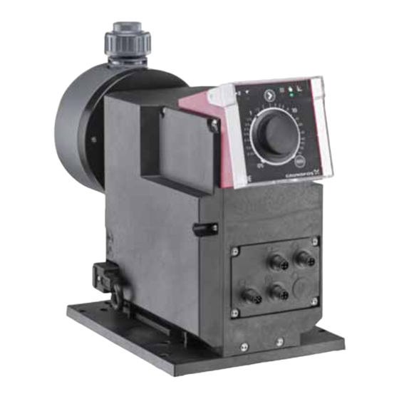
Page 8: Product Overview
3.6 Product overview Pos. Description section Control cube LEDs for status and operation mode Capacity adjusting knob [100%] key Signal inputs/outputs Mounting plate Mains connection [Operation mode] key Dosing head Valve, outlet side Deaeration valve Connection, deaeration hose Valve, inlet side Drain opening in case of diaphragm leakage Fig. -
Page 9: Technical Data / Dimensions
4. Technical data / Dimensions 4.1 Technical data Data 60-10 120-7 200-4 Turn-down ratio (setting range) [1:X] [l/h] Max. dosing capacity [gph] 15.8 52.8 [l/h] 0.075 0.15 0.25 Min. dosing capacity [gph] 0.0197 0.04 0.066 [bar] Max. operating pressure [psi] Max. - Page 10 Data 60-10 120-7 200-4 Max. load for level input 12 V, 5 mA Max. load for pulse input 12 V, 5 mA Max. load for external stop input 12 V, 5 mA Min. pulse length [ms] Signal input Max. pulse frequency [Hz] Max.
-
Page 11: Technical Data For Cip (Clean-In-Place) Applications
4.2 Technical data for CIP (Clean-In-Place) applications Short-term temperature limits for max. 40 minutes at max. 2 bar operating pressure: Max. liquid temperature for dosing head material PVDF [°C] Max. liquid temperature for dosing head material stainless steel [°C] The dosing head material Polyvinyl chloride (PVC) must not be used in CIP applications. 4.3 Dimensions 4 x Ø... -
Page 12: Assembly And Installation
5. Assembly and installation 5.1.3 Installing the pump on the mounting plate 1. Remove the locking screws from their transport 5.1 Pump assembly position on the mounting plate. 2. Place the pump on the mounting plate support Install the pump in such a way that the clamps and slide it in as far as possible. -
Page 13: Adjusting The Control Cube Position
4. Carefully lift off the control cube only so far from Faultless function can only be guaranteed in the pump housing that no tensile stress is conjunction with lines supplied by Grundfos. produced on the flat band cable. The lines used must comply with the pressure limits –... - Page 14 Hose connection, type U3U3 Pipe connection, type U3U3 For details on connection types, see section For details on connection types, see section 3.5 Type key. 3.5 Type key. 1. Make sure the system is pressureless. 1. Make sure the system is pressureless. 2.
-
Page 15: Electrical Connection
Pipe connection, types A1A1, A3A3, A7A7 5.3 Electrical connection For details on connection types, see section Mains connection 3.5 Type key. The mains plug is the separator separating the pump 1. Make sure the system is pressureless. from the mains. 2. - Page 16 Wiring diagram of the electrical connections Symbol Function Pin assignment 1/brown 2/white 3/blue 4/black Analog GND/(-) mA (+) mA External stop Pulse Low-level signal Empty signal Service connection (only for Grundfos service) 1/brown 2/white 3/blue 4/black Relay 1 Relay 2...
-
Page 17: Startup
6. Startup 6.2 Starting up and deaerating the pump 1. Read section 6.1 Preparing the pump for startup. 6.1 Preparing the pump for startup 2. Set the capacity adjusting knob to 0 %. 3. Switch on the power supply. CAUTION 4. -
Page 18: Operation
7. Operation 7.1.1 Capacity adjusting knob The capacity adjusting knob is used to set the 7.1 Operating elements capacity in percent of the maximum dosing flow of the pump. Due to the logarithmic increase of the percent values, even small dosing capacities can be set accurately. -
Page 19: Keys And Leds (Dde-Ar)
7.1.3 Keys and LEDs (DDE-AR) 7.2 Operation modes When pressing and holding down the [100%] key, the Following operation modes are available: pump doses at 100 % for a certain time. The [100%] • Manual, see section 7.2.1 Manual key can be used e.g. for deaeration. •... -
Page 20: Analog
7.2.3 Analog 7.3 Inputs/outputs Applies to DDE-AR control variant. Applies to DDE-AR control variant. In this operation mode, the pump doses according to 7.3.1 External stop the external analog signal. The dosing volume is The pump can be stopped via an external proportional to the signal input value in mA. -
Page 21: Relay Outputs
7.3.3 Relay outputs Applies to DDE-AR control variant. The pump can switch two external signals using internal relays. The relay outputs are potential-free. The connection diagram of the relays is shown in section 5.3 Electrical connection. Relay 1 is allocated with the alarm signals (see section Faults) as standard. -
Page 22: Service
8.3 Perform service Where necessary, replace worn parts with original spare parts made from suitable materials. Only spare parts and accessories from Grundfos For the full range of service kits and spare parts see should be used for maintenance. The usage of... -
Page 23: Service Overview
8.3.1 Service overview 5a 5b 1d 1f 1b 1c Fig. 13 DDE 60-10 5a 5b 1d 1f 1b 1c Fig. 14 DDE 120-7 / DDE 200-4 Pos. Components Pos. Components Cover plate (plastic dosing heads only) Deaeration screw Washers (stainless steel dosing heads 1a, 1e O-ring only) Valve ball... -
Page 24: Dismantling The Dosing Head, Diaphragm And Valves
15. Check the safety diaphragm (10) for wear and 10. Cross-tighten screws (6) with a torque wrench. damage. If the safety diaphragm is damaged, – Torque [Nm]: 6 (+ 1). send the pump to Grundfos for repair. See 11. Install new valves (4, 7). section Repairs. -
Page 25: Replacing The Deaeration Valve
This procedure requires a special tool kit. See service kit catalogue: 11. Put in O-ring (5b). • http://net.grundfos.com/qr/i/96488862_23 12. Use special tool (B) to screw in the new double nipple (5a) carefully with a torque wrench. – Torque [Nm]: 3 (+/- 0.2). -
Page 26: Diaphragm Leakage
13. Check the safety diaphragm (10) for wear and 8.4.1 Dismantling the dosing head, damage. If the safety diaphragm is damaged, diaphragm and valves in case of send the pump to Grundfos for repair. See diaphragm leakage. section Repairs. -
Page 27: Repairs
For pump repair contact your local Grundfos supplier. If your local Grundfos supplier asks you to send the pump to Grundfos for repair, fill in the safety declaration in English and attach it to the pump for shipping. The safety declaration can be found at the end of these instructions. -
Page 28: Faults
4.1 Technical data. • Incorrectly installed • Install the diaphragm diaphragm correctly. • Damage to gears • Contact your Grundfos service partner. • Hall sensor failure • Motor failure Motor blocked • Leaky/dirty outlet valve. • Replace valve if (Alarm) Dosing medium flows back necessary. -
Page 29: Indicated Faults For Dde-Ar
4.1 Technical data. • Incorrectly installed • Install the diaphragm diaphragm correctly. • Damage to gears • Contact your Grundfos service partner. • Hall sensor failure • Motor failure Motor blocked • Leaky/dirty outlet valve. • Replace valve if (Alarm) Dosing medium flows back necessary. -
Page 30: General Faults
10. Disposal This product or parts of it must be disposed of in an environmentally sound way. Use appropriate waste collection services. If this is not possible, contact the nearest Grundfos company or service workshop. See also end-of-life information at www.grundfos.com/product-recycling. - Page 31 Appendix Safety declaration Please copy, fill in and sign this sheet and attach it to the pump returned for service. Fill in this document using English or German language. Product type (nameplate) Model number (nameplate) Dosing medium Fault description Please make a circle around the damaged parts. In the case of an electrical or functional fault, please mark the cabinet.
- Page 32 Argentina China Germany Bombas GRUNDFOS de Argentina S.A. Grundfos Alldos GRUNDFOS Water Treatment GmbH Ruta Panamericana km. 37.500 Centro Dosing & Disinfection Reetzstraße 85 Industrial Garin ALLDOS (Shanghai) Water Technology D-76327 Pfinztal (Söllingen) 1619 - Garin Pcia. de B.A. Co. Ltd.
- Page 33 Phone: +40 21 200 4100 Telefax: +66-2-725 8998 Phone: +82-2-5317 600 Telefax: +40 21 200 4101 Turkey Telefax: +82-2-5633 725 E-mail: romania@grundfos.ro GRUNDFOS POMPA San. ve Tic. Ltd. Latvia Russia Sti. SIA GRUNDFOS Pumps Latvia ООО Грундфос Россия Gebze Organize Sanayi Bölgesi Deglava biznesa centrs ул.
- Page 34 98767824 0219 ECM: 1246835 www.grundfos.com...
Need help?
Do you have a question about the SMART Digital XL - DDE Series and is the answer not in the manual?
Questions and answers