
Related Manuals for Grundfos SMART Digital S DDC Series


Summary of Contents for Grundfos SMART Digital S DDC Series
- Page 1 GRUNDFOS INSTRUCTIONS SMART Digital S - DDC up to 15 l/h Installation and operating instructions Further languages http://net.grundfos.com/qr/i/95726994...
-
Page 2: Table Of Contents
English (GB) Installation and operating instructions Original installation and operating instructions Display Setup 6.7.1 Units CONTENTS 6.7.2 Additional display Inputs/Outputs Page 6.8.1 Relay outputs Safety instructions 6.8.2 External stop Symbols used in this document 6.8.3 Empty and Low level signals Qualification and training of personnel Basic settings Safety instructions for the operator/user... -
Page 3: Safety Instructions
1. Safety instructions 1.3 Safety instructions for the operator/user The safety instructions described in these These installation and operating instructions contain instructions, existing national regulations on health general instructions that must be observed during protection, environmental protection and for accident installation, operation and maintenance of the pump. -
Page 4: Dosing Chemicals
Should you have any questions regarding health and damage to property from escaping the material resistance and suitability of dosing liquid. the pump for specific dosing media, please • Never operate the pump with damaged or loose contact Grundfos. dosing head screws. -
Page 5: General Information
Grundfos cannot be held liable • Continuous dosing, as the medium is sucked up for any damage resulting from incorrect with a short suction stroke, regardless of the use. -
Page 6: Symbols On The Pump
2.3 Symbols on the pump Symbol Description Indication of universally dangerous spot. In case of emergency and prior to all maintenance work and repairs, take the mains plug out of the mains supply! The device complies with electrical safety class II. Connection for deaeration hose at dosing head. -
Page 7: Type Key
Hose, 3/8" x 1/2" (up to 60 l/h, 10 bar) Mains plug USA, Canada Australia, New Zealand, Taiwan Switzerland Japan Argentina Design Grundfos * Including: 2 pump connections, foot valve, injection unit, 6 m PE discharge hose, 2 m PVC suction hose, 2 m PVC deaeration hose (4/6 mm). -
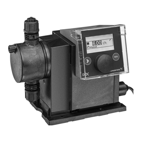
Page 8: Product Overview
2.6 Product overview Control cube Graphic LC display (section 6.2.2) Click wheel (section 6.1) [Start/stop] key (section 6.1) [100 %] key (section 6.1) Signal inputs/outputs (section 4.3) Mains connection Mounting plate Fig. 2 Front view of the pump Valve, discharge side Control cube assembly screws Deaeration valve... -
Page 9: Technical Data / Dimensions
3. Technical data / Dimensions 3.1 Technical data Data 6-10 15-4 Turn-down ratio (setting range) [1:X] 1000 1000 1000 [l/h] 15.0 Max. dosing capacity [gph] [l/h] 3.00 4.50 7.50 Max. dosing capacity with SlowMode 50 % [gph] 0.75 1.20 2.00 [l/h] 1.50 2.25... - Page 10 Data 6-10 15-4 100-240 V, - 10 %/+ 10 %, Voltage 50/60 Hz Length of mains cable Max. inrush current for 2 ms (100 V) Electrical Max. inrush current for 2 ms (230 V) data Max. power consumption P Enclosure class IP65, Nema 4X Electrical safety class Pollution degree...
-
Page 11: Dimensions
3.2 Dimensions 17.5 G 5/8" 4 x Ø6 Fig. 4 Dimensional sketch Pump type A [mm] A1 [mm] B [mm] C [mm] D [mm] DDC 6-10 46.5 DDC 9-7 46.5 DDC 15-4 200.5 39.5... -
Page 12: Assembly And Installation
4. Assembly and installation 4.1.3 Engage pump in mounting plate 1. Attach the pump to the mounting plate support For use in Australia: clamps and slide under slight pressure until it engages. Installation of this product must comply with AS/NZS3500! Note Certificate of suitability number: CS9431 RCM number: N20683... -
Page 13: Hydraulic Connection
Grundfos tank. Faultless function can only be guaranteed in conjunction with lines supplied by Caution... -
Page 14: Electrical Connection
4.3 Electrical connection The mains plug is the separator separating the pump from the mains. Warning Note The rated voltage of the pump, see section The enclosure class (IP65/Nema 4X) is Nameplate, must conform to local only guaranteed if plugs or protective caps conditions. - Page 15 Analog, External stop and pulse input Pins Function 1/brown 2/white 3/blue 4/black Analog GND/(-) mA (+) mA External stop Pulse Level signals: Empty signal and Low-level signal Pins Function Low-level signal Empty signal Relay outputs* Pins Function 1/brown 2/white 3/blue 4/black Relay 1 Relay 2...
-
Page 16: Startup
5. Startup 5.1 Setting the menu language For description of control elements, see section 6. 1. Turn click wheel to highlight the cog symbol. Operation 7.50 Manual Operation 2. Press the click wheel to open the "Setup" menu. 7.50 Manual Setup 3. -
Page 17: Deaerating The Pump
5.2 Deaerating the pump Warning The deaeration hose must be connected correctly and inserted into a suitable tank! 1. Open deaeration valve by approximately half a turn. 2. Press and hold down the [100 %] key (deaeration key) until liquid flows continuously without any bubbles from the deaeration hose. - Page 18 Calibration process - example for DDC 6-10 1. Fill a measuring beaker with dosing medium. Recommended filling volumes V – DDC 6-10: 0.3 l – DDC 9-7: 0.5 l = 300 ml – DDC 15-4: 1.0 l 2. Read off and note down the fill volume V (e.g.
-
Page 19: Operation
6. Operation 6.2 Display and symbols 6.2.1 Navigation 6.1 Control elements In the "Info", "Alarm" and "Setup" main menus, the The pump control panel includes a display options and submenus are displayed in the rows and the following control elements. below. -
Page 20: Overview Of Display Symbols
6.2.4 Overview of display symbols The following display symbols may appear in the menus. Top row with main menus (Sect. 6.3) Operation Back Info Alarm Run display Running - rotates when pump is dosing Setup Blocked drive - flashing symbol Operation 7.48 Pulse... -
Page 21: Main Menus
6.3.3 Alarm 6.3 Main menus You can view errors in the "Alarm" main The main menus are displayed as symbols at the top menu. of the display. The currently active main menu is displayed as text. Alarm 6.3.1 Operation Status information such as the dosing flow, selected operation mode and operating state Empty is displayed in the "Operation"... -
Page 22: Operation Modes
6.4 Operation modes The dosing volume per pulse is set in ml/pulse in the "Operation" menu using the click wheel. The setting Three different operation modes can be set in the range for the dosing volume depends on the pump "Setup >... -
Page 23: Slowmode
6.6 Key lock If the input value in operation mode 4-20 mA falls below 2 mA, an alarm is displayed and the pump The key lock is set in the "Setup > Key lock" stops. A cable break or signal transmitter error has menu by entering a four-digit code. -
Page 24: Additional Display
6.7.2 Additional display 6.8.1 Relay outputs The additional display provides additional Applies to DDC-AR control variant information about the current pump status. The value The pump can switch two external signals using is shown in the display with the corresponding installed relays. -
Page 25: Empty And Low Level Signals
6.8.3 Empty and Low level signals 7. Service In order to monitor the fill level in the tank, In order to ensure a long service life and a dual-level control unit can be connected to the dosing accuracy, wearing parts such as pump. -
Page 26: Service System
7.3 Service system 7.4 Perform service According to the motor runtime service requirements Only spare parts and accessories from Grundfos will appear. Service requirements appear regardless should be used for maintenance. The usage of of the current operating state of the pump and do not non-original spare parts and accessories renders affect the dosing process. -
Page 27: Dismantling The Diaphragm And Valves
7.4.2 Dismantling the diaphragm and valves 7.4.3 Reassembling the diaphragm and valves The pump must only be reassembled, if nothing Warning indicates that dosing liquid has entered the pump Danger of explosion, if dosing liquid has housing. Otherwise proceed as described in entered the pump housing! section 7.6.2 Dosing liquid in the pump... -
Page 28: Diaphragm Breakage
If dosing liquid has entered the pump housing: • Never operate the pump with blocked or soiled • Send the pump to Grundfos for repair, following drain opening. the instructions given in section Repairs. – If the drain opening is blocked or soiled, •... -
Page 29: Repairs
Observe section Alarm 7.6 Diaphragm breakage. If the above requirements are not met, Grundfos may Empty refuse to accept delivery of the pump. The shipping costs will be charged to the sender. Low level... -
Page 30: List Of Faults
8.1 List of faults 8.1.1 Faults with error message Display in the Possible cause Possible remedy "Alarm" menu Empty • Dosing medium tank empty • Fill tank. (Alarm) • Check contact setting (NO/NC). Low level • Dosing medium tank almost empty (Warning) •... -
Page 31: General Faults
This product or parts of it must be disposed of in an environmentally sound way: 1. Use the public or private waste collection service. 2. If this is not possible, contact the nearest Grundfos company or service workshop. Subject to alterations. - Page 32 Argentina China Germany Bombas GRUNDFOS de Argentina S.A. Grundfos Alldos GRUNDFOS Water Treatment GmbH Ruta Panamericana km. 37.500 Centro Dosing & Disinfection Reetzstraße 85 Industrial Garin ALLDOS (Shanghai) Water Technology D-76327 Pfinztal (Söllingen) 1619 - Garin Pcia. de B.A. Co. Ltd.
- Page 33 Phone: +381 11 26 47 877 / 11 26 47 Telefax: +66-2-725 8998 Malaysia Turkey Telefax: +381 11 26 48 340 GRUNDFOS Pumps Sdn. Bhd. GRUNDFOS POMPA San. ve Tic. Ltd. Singapore 7 Jalan Peguam U1/25 Sti. Glenmarie Industrial Park GRUNDFOS (Singapore) Pte. Ltd.
- Page 34 95726994 0817 ECM: 1214328 www.grundfos.com...
Need help?
Do you have a question about the SMART Digital S DDC Series and is the answer not in the manual?
Questions and answers