Table of Contents
Advertisement
Quick Links
Advertisement
Chapters
Table of Contents

Subscribe to Our Youtube Channel
Related Manuals for Grundfos SMART Digital DDA


Summary of Contents for Grundfos SMART Digital DDA
- Page 1 GRUNDFOS INSTRUCTIONS SMART Digital - DDA Installation and operating instructions...
-
Page 2: Declaration Of Conformity
Declaration of conformity GB Declaration of Conformity We, Grundfos Alldos, declare under our sole responsibility that the products DDA, DDC and DDE, to which this declaration relates, are in conformity with these Council directives on the approximation of the laws of the EC member states: –... -
Page 3: Table Of Contents
English (GB) Installation and operating instructions Original installation and operating instructions. Analog output SlowMode CONTENTS FlowControl Pressure monitoring Page 6.8.1 Pressure setting ranges Safety instructions 6.8.2 Calibration of pressure sensor Identification of safety instructions in Flow measurement these instructions 6.10 AutoFlowAdapt Qualification and training of personnel 6.11... -
Page 4: Safety Instructions
1. Safety instructions These installation and operating instructions contain 1.3 Safety instructions for the general instructions that must be observed during operator/user installation, operation and maintenance of the pump. The safety instructions described in these It must therefore be read by the installation engineer instructions, existing national regulations on health and the relevant qualified operator prior to protection, environmental protection and for accident... -
Page 5: Dosing Chemicals
Grundfos cannot be held operating pressure. liable for any damage resulting from incorrect use. Ensure that parts in contact with the... -
Page 6: Warranty
2.3 Warranty A guarantee claim in accordance with our general terms of sale and delivery is only valid if the following requirements are fulfilled: • The pump is used in accordance with the information within this manual. • The pump is not dismantled or incorrectly handled. •... -
Page 7: Type Key
EU (Schuko) USA, Canada Australia, New Zealand, Taiwan Switzerland Japan Argentina Design Grundfos Alldos *) including: 2 pump connections, foot valve, injection unit, 6 m PE discharge hose, 2 m PVC suction hose, 2 m PVC deaeration hose (4/6 mm) -
Page 8: Device Overview
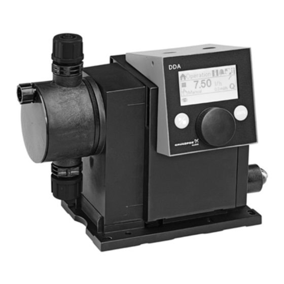
2.6 Device overview Control cube Graphic LC display (Sect. 6.2.2) Click wheel (Sect. 6.1) Start/stop key 100 % key (Sect. 6.1) 100% 100% (Sect. 6.1) Signal inputs, outputs (Sect. 4.3) Mains connection Mounting plate Fig. 2 Front view of the pump Valve, discharge side Control cube assembly screws... -
Page 9: Technical Data / Dimensions
3. Technical data / dimensions 3.1 Technical data DDA pump type Data 7.5 - 16 12-10 17-7 30-4 Turndown ration (setting range) [1:X] 3000 1000 1000 1000 [l/h] 12.0 17.0 30.0 Max. dosing flow [gph] [l/h] 3.75 6.00 8.50 15.00 Max. - Page 10 DDA pump type Data 7.5 - 16 12-10 17-7 30-4 Voltage 100-240 V, 50-60 Hz Length of mains cable Max. current consumption (100 V) Electrical Max. current consumption (230 V) data Max. power consumption P 18 / 24 Enclosure class IP 65, Nema 4X Electrical safety class Max.
-
Page 11: Dimensions
3.2 Dimensions 17.5 G 5/8" 100% 4 x Ø6 Fig. 4 Dimensional drawing Pump type A [mm] A1 [mm] B [mm] C [mm] D [mm] DDA 7.5 - 16 46.5 DDA 12-10/17-7 200.5 39.5 DDA 30-4 204.5 35.5 38.5... -
Page 12: Assembly And Installation
4. Assembly and installation 4.1.3 Engage pump in mounting plate 1. Attach the pump to the mounting plate support 4.1 Pump assembly clamps and slide under slight pressure until it engages. The pump is delivered with a mounting plate. The mounting plate can be mounted vertically e. -
Page 13: Hydraulic Connection
< 1 l/h we recommend the use of an with a suction line, level switch and multifunction additional spring-loaded valve (approx. 3 bar) on valve on a Grundfos tank. the discharge side for the safe generation of the necessary differential pressure. -
Page 14: Electrical Connection
4.3 Electrical connection Warning The enclosure class (IP65 / Nema 4X) is only guaranteed if plugs or protective caps are correctly installed! Warning The pump can start automatically when the mains voltage is switched on! Do not manipulate mains plug or cable! The rated voltage of the pump, see section 2.4 Nameplate, must conform to local conditions. - Page 15 Analog, external stop and pulse input Pins Function Plug type 1/brown 2/white 3/blue 4/black Analog GND/ (-) mA (+) mA mA signal External stop Pulse Pulse Pulse Level signals: empty and low-level signal Pins Function Plug type 1/brown 2/white 3/blue 4/black Low-level signal Pulse...
-
Page 16: Commissioning
5. Commissioning 5.1 Setting the menu language For description of control elements, see Section 6. Operation 7.50 1. Turn click wheel to highlight the cog symbol. Manual Operation 2. Press the click wheel to open the ’Setup’ menu. 7.50 Manual Setup Language English >... -
Page 17: Deaerating The Pump
5.2 Deaerating the pump Warning The deaeration hose must be connected correctly and inserted into a suitable tank! 1. Open deaeration screw by approximately half a turn. 2. Press and hold down the 100 % key (deaeration key) until liquid flows continuously without any bubbles from the deaeration hose. - Page 18 Calibration process - example for DDA 7.5 - 16 1. Fill a measuring beaker with dosing medium. = 300 ml Recommended filling volumes: DDA type 7.5 - 16 12-10 17-7 30-4 Medium V 0.3 l 0.5 l 1.0 l 1.5 l 2.
-
Page 19: Operation
6. Operation 6.2 Display and symbols 6.2.1 Navigation 6.1 Control elements In the ’Info’, ’Alarm’ and ’Setup’ main menus, the The pump control panel includes a display options and submenus are displayed in the rows and the following control elements. below. -
Page 20: Overview Of Display Symbols
6.2.4 Overview of display symbols The following display symbols may appear in the menus. Top row with main menus (Sect. 6.3) Operation Back Info Run display Alarm Running - rotates when pump is dosing Setup Blocked drive - flashing symbol Operation 7.48 Manual... -
Page 21: Main Menus
6.3 Main menus 6.3.3 Alarm You can view errors in the ’Alarm’ main menu. The main menus are displayed as symbols at the top of the display. The currently active main menu is displayed as text. Alarm 6.3.1 Operation 12.02.2010 12:34 Status information such as the dosing flow, Empty... -
Page 22: Operation Modes
6.4 Operation modes 6.4.2 Pulse In this operation mode, the pump doses the Six different operation modes can be set in the set dosing volume for each incoming (potential-free) ’Setup > Operation mode’ menu. pulse, e. g. from a water meter. There is no direct •... -
Page 23: Analog 0/4-20 Ma
6.4.3 Analog 0/4-20 mA Set analog scaling In this operation mode, the pump doses Analog scaling refers to the assignment of the according to the external analog signal. The current input value to the dosing flow. dosing volume is proportional to the signal input Analog scaling passes through the two reference value in mA. -
Page 24: Batch (Pulse-Based)
Set analog scaling in the ’Operation’ menu The batch volume (e. g. 75 ml) is set in the ’Setup > Batch volume’ menu. The minimum dosing time Analog scaling can also be modified after a security required for this (e. g. 32 seconds) is displayed and prompt directly in the ’Operation’... -
Page 25: Dosing Timer, Cycle
6.4.5 Dosing timer, cycle The total batch volume (e. g. 125 ml) and the remaining batch volume still to be dosed are In this operation mode, the pump doses the displayed in the ’Operation’ menu. During breaks in set batch volume in regular cycles. Dosing dosing, the time until the next dosing process starts when the pump is started after a singular start (e. -
Page 26: Analog Output
The batch volume (e. g. 80.5 ml) is set in the ’Setup Wiring diagram see section 4.3 Electrical > Dos. Timer Week’ menu. The minimum dosing time connection. required for this (e. g. 0:34) is displayed and can be In all modes, the analog output has a increased. -
Page 27: Flowcontrol
6.7 FlowControl Setting FlowControl The ’FlowControl’ function is set using the two FC/FCM control variant. parameters ’Sensitivity’ and ’Delay’ in the ’Setup > This function is used to monitor the dosing process. FlowControl’ menu. Although the pump is running, various influences e. -
Page 28: Pressure Monitoring
6.8 Pressure monitoring 4. Proceed as described below to calibrate: FC/FCM control variant. Plug in pressure sensor plug or select A pressure sensor monitors the pressure in the ’Setup > FlowControl active’ menu dosing head. If the pressure during the discharge phase falls below 2 bar, a warning is generated (pump continues running). -
Page 29: Flow Measurement
6.9 Flow measurement Examples of ’AutoFlowAdapt’ Pressure fluctuations FCM control variant The dosing volume decreases as backpressure The pump accurately measures the actual flow and increases and conversely the dosing volume displays it. Via the 0/4 - 20 mA analog output, the increases as the backpressure decreases. -
Page 30: Key Lock
6.12 Key lock 6.13.2 Additional display Additional display provides additional information The key lock is set in the ’Setup > Key lock’ about the current pump status. The value is shown in menu by entering a four-digit code. It protects the the display with the corresponding symbol. -
Page 31: Time/Date
6.14 Time/date 6.16 Inputs/outputs The time and date can be set in the ’Setup > In the ’Setup > Inputs/outputs’ menu, you can Time+date’ menu. configure the two outputs ’Relay 1+2’ and the signal inputs ’External stop’, ’Empty signal’ and ’Low level The conversion between summer and signal’. -
Page 32: External Stop
Timer, cycle (relay 2) 6.16.3 Empty and low-level signals For the ’Relay 2 > Timer cycle’ function, set the In order to monitor the filling level in the following parameters: tank, a dual-level sensor can be connected to the pump. The pump responds to the signals as follows: •... -
Page 33: Service
7.2 Perform service (see fig. 3). Only spare parts and accessories from Grundfos Take suitable precautions to prevent should be used for maintenance. The usage of non- harm to health and damage to property... -
Page 34: Dosing Head Overview
8. Remove the cover (9). to dispatch! 9. Undo screws (8) on the dosing head (7) and If the above requirements are not met, Grundfos may remove with discs. refuse to accept delivery of the pump. The shipping 10. Remove the dosing head (7). -
Page 35: Faults
8. Faults In the event of faults in the dosing pump, a warning or an alarm is triggered. The corresponding fault symbol flashes in the ’Operation’ menu, see section 8.1 List of faults. The cursor jumps to the ’Alarm’ main menu symbol. Press the click wheel to open the ’Alarm’... -
Page 36: List Of Faults
8.1 List of faults 8.1.1 Faults with error message Display in the Possible cause Possible remedy ’Alarm’ menu Empty • Dosing medium tank empty • Fill tank. (Alarm) • Check contact setting (NO/NC) Low level • Dosing medium tank almost empty (Warning) •... - Page 37 Display in the Possible cause Possible remedy ’Alarm’ menu • Broken FlowControl cable • Check plug connection. • Sensor defect • Change sensor if necessary. Pressure sensor • Pressure sensor not correctly • Calibrate pressure sensor correctly (Warning) calibrated. (see section 6.8.2 Calibration of pressure sensor).
-
Page 38: General Faults
Use appropriate waste collection services. If there is no such facility or the facility refuses to accept thse materials used in the product, the product can be sent to the nearest Grundfos company or Grundfos service centre. Subject to alterations. - Page 39 Appendix Safety declaration Please copy, fill in and sign this sheet and attach it to the pump returned for service. Product type (nameplate) Model number (nameplate) Dosing medium Fault description Please make a circle around the damaged parts. In the case of an electrical or functional fault, please mark the cabinet. 100% Please describe the error / cause of the error in brief.
- Page 42 Telefax: +54-3327 411 111 Export Processing Zone infoservice@grundfos.de Korea Pudong New Area Service in Deutschland: Australia GRUNDFOS Pumps Korea Ltd. Shanghai, 201206 E-mail: GRUNDFOS Pumps Pty. Ltd. 6th Floor, Aju Building 679-5 Phone: +86 21 5055 1012 kundendienst@grundfos.de P.O. Box 2040...
- Page 43 Poland Sweden Usbekistan Представительство GRUNDFOS Pompy Sp. z o.o. GRUNDFOS AB ГРУНДФОС в Ташкенте ul. Klonowa 23 (Box 333) Lunnagårdsgatan 6 700000 Ташкент ул.Усмана Baranowo k. Poznania 431 24 Mölndal Носира 1-й PL-62-081 Przeźmierowo Tel.: +46(0)771-32 23 00 тупик 5...
- Page 44 Thinking ahead makes it possible Innovation is the essence 15.720310 V1.0 95724708 1110 ECM: 1065172 The name Grundfos, the Grundfos logo, and the payoff Be–Think–Innovate are registrated trademarks owned by Grundfos Management A/S or Grundfos A/S, Denmark. All rights reserved worldwide. www.grundfosalldos.com...
Need help?
Do you have a question about the SMART Digital DDA and is the answer not in the manual?
Questions and answers