AAT v-max+ Translation Of The Original User Manual
Pushing and braking aid
Hide thumbs
Also See for v-max+:
- Translation of the original user manual (55 pages) ,
- User manual (32 pages) ,
- User manual (32 pages)
Table of Contents
Advertisement
Quick Links
Advertisement
Table of Contents

Related Manuals for AAT v-max+


Summary of Contents for AAT v-max+
- Page 1 Pushing and Braking Aid Translation of the original user's manual...
-
Page 2: Ce Declaration Of Conformity
CE Declaration of conformity The company AAT Alber Antriebstechnik GmbH herewith declares that the products of the power system v-max + are developed and manufactured ac- cording to the general guidelines 2007/47/EG and 2006/42/EG of the Eu- ropean Union. This declaration loses all validity, if the above mentioned devices have been tampered with or changed in any way without the knowledge and agreement of the company AAT Alber Antriebstechnik. -
Page 3: Table Of Contents
Table of contents CE Declaration of conformity ... . Table of contents ....General information ..... How to use this user's manual . - Page 4 Care, maintenance and recycling....New user ..... Charger .
-
Page 5: General Information
Instruction on how to operate the device is part of the delivery package and takes place with your authorized dealer or an AAT representative. Please read this user’s manual carefully and particularly take note of the safety instructions before you use the movilino for the first time. -
Page 6: Description Of The Product
Said person should be able to sit properly without help, otherwise you should secure them with a safety belt. The latter is an accessory available at AAT Alber Antriebstechnik GmbH. In addition, the arms of the person to be transported should not protrude over the arm rests of the wheelchair during the transportation process. -
Page 7: General Survey
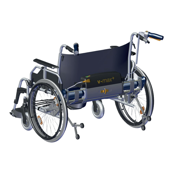
General survey Œ = control grip = v-max + power unit Ž = heavy-duty wheels incl. handrim and toothed ring = brackets on the wheelchair = mega battery pack incl. bag ‘ = pushing grip... - Page 8 2.2.1 Control grip Œ = speed control = rocker switch backwards/forwards Ž = link to hold grips = helix cable 2.2.2 Power unit Œ = control grip = power switch Ž = driving unit's link to the wheelchair ...
-
Page 9: Technical Data
Technical data height = 275 mm Measurements width = 630 mm depth = 185 mm power unit incl. handle = 13,5 kg mega battery pack = 14,3 kg power cable = 0,2 kg Weight bag for batteries incl. velcro straps = 0,3 kg charger = 0,3 kg total weight = 28,6 kg Limits for mounting the v-max + on a wheelchair... -
Page 10: Dimensioned Sketch
Dimensioned sketch... -
Page 11: Standard Scope Of Delivery
Standard scope of delivery The following is part of the standard scope of delivery: Œ = heavy duty wheel incl. handrim and toothed ring = v-max + power unit plus handle Ž = charger incl. user's manual = mega battery pack incl. bag ...as well as the components mounted to the wheelchair, power cable and bag for the battery pack plus the user’s manual (no... -
Page 12: Assembly And Initial Operation
This bracket may only be mounted by AAT or dealers authorized by AAT. Brackets All brackets are especially developed and adjusted to each individual bracket, Œ... -
Page 13: Hook On The V-Max
Hook on the v-max + v-max + To mount the the powered axles must be inserted entirely. Press Πthe two slide switch toward the PRESS button until they lock. See picture on the right. v-max + Now slide the evenly, on both sides, into the brackets. - Page 14 Now you press the PRESS button to unlock the levers and the powered ax- les come out. ΠThe power unit is activated, if both slide switch have reached their ou- position. The driving unit locked properly, if the wheelchair cannot be moved ma- nually any more.
-
Page 15: Detach The V-Max
Œ Then you put the other plug of the power cable into its socket on the mega battery pack. Please make sure that the power cable’s plug is dry and clean. If the device is already attached to the wheelchair (as described in chap- ter 3.3), the v-max + is now ready to use. - Page 16 3.5.1 Attaching the grips Due to the special toothing (see picture) it is possible to insert the grips into the receptacles in the most comfortable position for each individual users. See picture on the right indicating the grip positions which have proven most comfortable for frequent use.
-
Page 17: Functional Check
In case you do not need the device for some time, simply remove the grips v-max + (see pictu- and put them back into their respective holders on the re). This way the grips turn into stable feet for the v-max + so you can simply set it aside. -
Page 18: Safety Instructions And Hazard Notes
Safety instructions and hazard notes For a safe operation of the v-max it is important that you observe and adhere to all warning signs and instructions in this user’s manual as well as the warning signs and instructions on the device itself. -
Page 19: Instruction
(see chap- 2.3) At this point check the device before operation. Should your v-max function properly, please call your local dealer or AAT directly. Please note that the surface temperature of the v-max + could be increased due to the influence of external heat sources like sunlight. -
Page 20: Operation / Attendant
Thorough instruction into the use of the v-max by your dealer or a repre- sentative of AAT Alber Antriebstechnik is part of the delivery package and takes place at an appointment of your choice. This is a free service at no extra charge. -
Page 21: Power Unit
Mounting the brackets Attaching the v-max ’s brackets to the wheelchair or making changes on said brackets may only be performed by the company AAT Alber Antriebs- technik or their authorized dealers. The v-max + may only be attached to wheelchairs which must be checked according to generally acknowledged technical norms, and their operator’s... -
Page 22: Operation
Operation Maximum total weight Please note that the maximum total weight of 300 kg (wheelchair, person and v-max + ) is not exceeded. Mega battery pack Please make sure that the batteries are fully charged before you use the v-max + for the first time (extensive instructions you find in chapter 8.3) -
Page 23: Control And Display Elements
’s most important components to you. Your v-max + was prepared for you by AAT or your dealer so that when the device is properly mounted, locked and connected, it is ready to use as soon as you turn it on. -
Page 24: On/Off Push Button
6.1.3 Panic switch If during an emergency you press the rocker switch too hard so that the pressure point is overcome, the so-called panic switch causes the v-max to go from driving mode into coast. As long as you keep the rocker switch pressed, you can drive the patient away from the dangerous situation. -
Page 25: Charge Condition Of The Mega Battery Pack
Charge condition of the mega battery pack A number of light emitting diodes inform you about the batteries’ charge. They are located on the power unit next to the On/Off push button. The light emitting diodes and their meaning: The diode ligths up in - - the first green bar: mega battery pack is 100 % charged - the second green bar: mega battery pack is 80 % charged - the third green bar: mega battery pack is 60 % charged... -
Page 26: Control Light To Indicate Malfunction
Control light to indicate malfunction Malfunction is indicated by blinking of the red light emitting diode on the control panel. In case of malfunction, please first turn off the device and then on again. Should the device still indicate a malfunction, charge the mega battery pack in case of low voltage. -
Page 27: Trouble Shooting
Trouble shooting v-max + If there are problems using the please check the following trouble shooting chart and see whether you cannot fix them yourself. Problem Check and potential solution Is the charger connected to the v-max + ? If so, disconnect the charging cable and plug in the power cable Is the mega battery pack empty? If so, charge the batteries. -
Page 28: Accessories
We recommend the voltage converter for your vehicle, if you transport the v-max in your car. The AAT voltage converter is designed for a 12 V elec- Πtrical system. This voltage converter transforms 12 V / 24 V direct current (D.C.) into 230 V alternating current (A.C.). -
Page 29: Care, Maintenance And Recycling
Check the charger regularly and protect it from oils, grease, aggressive cleaning agents, thinners and/or damage by sharp edges, etc. Repairs and service check-ups may only be performed by AAT Alber An- triebstechnik GmbH or their authorized personnel. Please do not disassemble or modify the charger! - Page 30 Check the voltage converter regularly and protect it from oil, grease, ag- gressive cleaning agents, thinners and/or damage by sharp edges, etc. Repairs and service check-ups may only be performed by AAT Alber An- triebstechnik GmbH or their authorized personnel.
-
Page 31: Mega Battery Pack
It is considered as safe as dry cells and admitted to air travel by DOT and IATA. Always charge your battery pack with the AAT charger delivered with your v-max + . This particular charger automatically turns off when the batteries... - Page 32 Before charging, please read and follow all instructions and warning no- tes printed on the charger. Exclusively use the AAT Alber Antriebstechnik GmbH charger. Never touch the plug with moist hands! Signals of the charger...
-
Page 33: Fuse
AAT Alber Antriebstechnik GmbH or your lo- cal dealer to be recycled. A new law concerning electric and electronic devices (ElektroG) has been passed on March 24, 2005 regulating the taking back and recycling of old electric and electronic devices. -
Page 34: Warranty And Liability
Warranty and liability Warranty AAT Alber Antriebstechnik GmbH grants a warranty of two years for all its v-max + products of type including all its accessory parts (with the excepti- on of the sealed lead acid batteries). The warranty begins at the date of purchase and covers failure of material and errors in manufacturing. - Page 36 AAT Alber Antriebstechnik GmbH Postfach 10 05 60 · D-72426 Albstadt Tel.: 0 74 31 - 12 95 0 · Fax.: 0 74 31 - 12 95 35 Email: info@aat-online.de · www.aat-online.de...
Need help?
Do you have a question about the v-max+ and is the answer not in the manual?
Questions and answers