
Related Manuals for Den-Sin MERMAID E1100-I


Summary of Contents for Den-Sin MERMAID E1100-I
- Page 1 MERMAID E1100-I Electrical Powered Heavy Duty Cold Water HIGH PRESSURE CLEANER USER GUIDE & SPARE PARTS MANUAL Original Instruction www.densin.com...
-
Page 2: Introductions
Introductions Congratulations on your purchase of the DEN-SIN MERMAID E1100-I Water Blaster. DEN-SIN makes no warranty of any kind with regards to this material, including, but not limited to, the implied warranties of merchantability and fitness for a particular purpose. -
Page 3: Operation Information
Correct way of holding the trigger gun for blasting due to the recoil force from the trigger gun. Understand how to operate the machine correctly. Basic Maintenance and Troubleshooting. ******For Den-sin’s Training program available, please enquiry****** IMPORTANT that user read the manual guide to understand the operation of the machine before usage. -
Page 4: Table Of Contents
El-box assembly (220V; 380~415V; 440V~480V, 50/60Hz) ..........50 5. Wiring Diagram ....................52 6. Declaration and Warranty ................... 53 7. Warranty ....................... 54 The information contained in this user guide is subject to change without notice. NOTE MERMAID E1100-I STD00 Page 3 of 54... -
Page 5: Getting Acquainted With Your Water Blaster
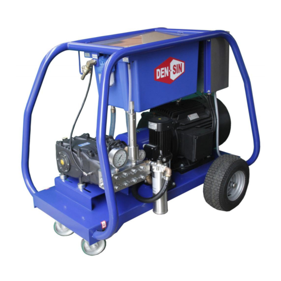
1. Getting acquainted with your Water Blaster Fast and efficient cleaning The DEN-SIN Mermaid E1100-I enables you to get more cleaning done in less time. This DEN-SIN cold water Blaster offers you high performance and a design optimized for heavy duty use. The design of the surrounding frame safeguard the vital parts during transport and use, and the high performance gives you the opportunity to solve an array of blasting tasks. -
Page 6: Applications
Remove the Water Blaster and its accessories from the packing material, if any. For transport and packing reasons some accessories are supplied disassembled. Standard items: Trigger Gun High Pressure Machine High Pressure Hose Manual/Spares Parts Water Coupling Nozzle MERMAID E1100-I STD00 Page 5 of 54... -
Page 7: High Pressure Machine Schematic Diagram Mermaid E800
When machine is over pressurized, the safety valve will start to open and excess water is dumped. The setting of the safety valve system is factory set, do not try to reset them. MERMAID E1100-I STD00 Page 6 of 54... -
Page 8: Hose Type
Always switch off and depressurize the machine before attach or CAUTION detached the hose to the machine. Machine ID Plate The information contained in this user guide is subject to change without notice. NOTE MERMAID E1100-I STD00 Page 7 of 54... -
Page 9: Machine Highlights
HP Pressure Gauge Min. Filter Pressure: Gauge ~4Bar HOT SURFACE is used to caution user of hot surface that may cause injuries. Any maintenance work to be done after the surfaces had cool down. MERMAID E1100-I STD00 Page 8 of 54... -
Page 10: High Pressure Machine Lockout/Tagout Procedure
2. When equipment is clear, remove all locks. Turn on the main switch, unlock the trigger gun lock and start the normal operating procedure to start using the high pressure machine. MERMAID E1100-I STD00 Page 9 of 54... - Page 11 Once the sealant cracked, it showed that unauthorized activities occur on the valves. Safety Valve: Tempered Proof Sealant Electrical Components To prevent unauthorized usage or sabotage, the electrical box & main switch is equipped with locks. 2 Locks System Main Switch Lock Hole MERMAID E1100-I STD00 Page 10 of 54...
-
Page 12: Machine Installation / Setup
Step 5. Turn on the water supply tap and fill the water tank with water. When water tank is full, the water will be cut off. Step 6. Connect the main power cord to a grounded 3-phase main power supply. MERMAID E1100-I STD00 Page 11 of 54... - Page 13 Refer to the ID-plate located at the electrical box or frame. Do not let the machine recycle the water (running with Spray-gun CAUTION trigger not activated) for more than 10 minutes; this can cause serious damage to the seals MERMAID E1100-I STD00 Page 12 of 54...
-
Page 14: Safety And Protection Information
20min continuously. Caution must be observe when working with trigger gun. Do not work continuously without rest in between jobs. Release any residual pressure from the gun when the machine is shut down CAUTION MERMAID E1100-I STD00 Page 13 of 54... -
Page 15: Important Medical Information
Inform the doctor of the cause of the injury. Show this card to the doctor. DEN-SIN - a division of Nilfisk-Advance Pte Ltd. 5 Tuas Ave 2, Singapore 639445 Tel: +65 6268 1006 Fax: +65 62684916 MEDICAL ALERT... -
Page 16: Safety Devices
6) The front castor can be locked in place to prevent the machine from rolling from an incline surface of not more than 10 Electrical Box Warning Castor Wheel with brake Pictogram * Pictures are for illustration purpose only MERMAID E1100-I STD00 Page 15 of 54... -
Page 17: Safely Transporting The Machine
6) Check the travel path is clear. 7) Ensure load is evenly distributed. Do not lift the machine from the frame. Only trained personal is require to do the lifting. Make sure the load evenly distributed. WARNING MERMAID E1100-I STD00 Page 16 of 54... -
Page 18: Safety Personal Protective Equipment (Ppe)
Hose protection- Protect user from high pressure water injuries incase hose connection is loose. The following protective clothing and devices should be worn both by personnel operating the water blaster system and equipment and by those working nearby. WARNING MERMAID E1100-I STD00 Page 17 of 54... -
Page 19: Safe Use Of Machine Guidelines
To prevent accidents from happening, ensure the safety of the person(s) who uses the equipment and to protect bystanders and nearby placed inventory or machinery, a few safety precautions needs attention jobs. WARNING MERMAID E1100-I STD00 Page 18 of 54... -
Page 20: Maintenance And Troubleshooting
Clean the motor fan cover. Cleaning of motor Clean the motor fan blade. fan ( to ensure sufficient airflow ) Do NOT operate the machine with damaged or fan cover removed! MERMAID E1100-I STD00 Page 19 of 54... -
Page 21: Machine Do`s And Don`ts
If any further inconveniences, not mentioned in this user guide or any damages of the machine, we strongly suggest you to make contact with your dealer for the repair or possible replacement of any original spare- parts. NOTE MERMAID E1100-I STD00 Page 20 of 54... -
Page 22: Troubleshooting
NOTE parts. MERMAID E1100-I STD00 Page 21 of 54... -
Page 23: Service Instructions
Step C) Before reassembly of the side covers, check the seal lips for wear. If replacement is necessary, position the new ring as shown in fig. 5. Make sure the shim rings have been inserted, before assembling the cover (sight glass side). MERMAID E1100-I STD00 Page 22 of 54... - Page 24 Position the two side covers on the crankcase, initially use N°3 screws M6x40 as shown in fig. 6, and then the fastening screws. The shaft’s rolling torque (with connecting rods coupled) must not exceed 8 Nm. MERMAID E1100-I STD00 Page 23 of 54...
- Page 25 Loosen the screws M8x100 that fix the liners to the head as shown in fig.12. Unfasten the head screws M12x260 N° 5 and N° 6 as shown in fig. 13. Replace it with the supplied 4 x 700953532 to prevent breaking of the plunger. (Important!!!!) 4pcs x 7009953532 MERMAID E1100-I STD00 Page 24 of 54...
- Page 26 At every valve inspection, always replace all the sealing rings and the OR rings between the liner and the head, between the head and the liner manifold in the area of the recirculation hole. Before reassembly, clean and dry off the components and all their seats inside the head. MERMAID E1100-I STD00 Page 25 of 54...
- Page 27 Remove the pumping assembly with a fork wrench and check for wear as indicated in fig. 24- 25; replace if necessary. 700953533 Deep Socket . Remove the M 6x40 screws of the liner support (fig. 26, position 1) and separate the support (fig.27) MERMAID E1100-I STD00 Page 26 of 54...
- Page 28 31, position 4) . At each disassembly, the HP packing (fig. 31,position 4) must be replaced. Assembly of the piston unit – supports – seals Insert the upper bush (fig.32, position 1) into the liner. MERMAID E1100-I STD00 Page 27 of 54...
- Page 29 Insert the anti-extrusion ring(fig.37/39,position 2) and the gasket bush(fig.37/ 39,position 3) The gasket bush (fig.38/ 39 , position 3) must be introduced into the liner with the outlets facing outwards (crankcase side) MERMAID E1100-I STD00 Page 28 of 54...
- Page 30 Reassemble the seals support unit as shown in fig. 42 – 43, replacing components (fig.43, position 1, 2, 3) Assemble the support - liner unit by manually screwing the M 6x40 screws (fig .44) then proceed with calibration using a torque wrench. MERMAID E1100-I STD00 Page 29 of 54...
- Page 31 The liner fastening screw must Liner fastening screws be tightened according to fig.45 The liner fastening screw must Support fastening screws be tightened according to fig.44 Lifting Bracket fastening screws Oil discharge plug Fig.45 MERMAID E1100-I STD00 Page 30 of 54...
- Page 32 Do not dispose used oil into drain. Always pour the used oil into recycle container or plastic bag with “Waste oil” labeled. Contact recycles company to collect the waste oil for proper dispose. Always let the pump cool before service MERMAID E1100-I STD00 Page 31 of 54...
-
Page 33: Spare Parts List
4. Spare parts list 4. Spare parts list Frame/ Water Tank Assembly MERMAID E1100-I STD00 Page 32 of 54... -
Page 34: Frame/ Water Tank Assembly Spare-Parts List
700540883 700540270 Hose Nipple 1”-1/2” (Water Drain) 700530831 EL Box Complete E800/1100 700510009 Bolt M8 x 16 Allen 700510005 Washer Flat M8 700510004 Locknut M8 700540316 M8 Dowty seal 700520121 Pipe Clamp (Continues) MERMAID E1100-I STD00 Page 33 of 54... -
Page 35: Motor/Pump Assembly
Bolt M10 x 35 Allen 700600816 Discharge Block (Outlet) Dowty Seal ½” 700540056 Nipple ½”-M24 700540224 700520218 Spacer 700510219 Bolt M16 x 1.5x 65 Hex 700510081 Washer Flat 18mm 700510082 Washer Spring 5/8” MERMAID E1100-I STD00 Page 34 of 54... -
Page 36: Booster Pump Assembly
Elbow 1” 700520204 Filter Complete w/o Cartridge Nipple ¾”-¾”M 700540226 700520205 Filter Cartridge Elbow ¾” 700540323 700540102 Hose Nipple 1”-3/4” 700540264 Hose Clip 1” Elbow ¾”-¾”F 700540880 700540306 Pressure Gauge 21Bar T-Joint ¾”-1/4” 700540557 MERMAID E1100-I STD00 Page 35 of 54... -
Page 37: Filter Assembly
1/2" FILTER c/w 25 MESH 700520507 FILTER CARTRIDGE 1/2", 5" 700540100 NIPPLE 1/2 NPT - 1/2 BSPM 700540056 DOWTY SEAL 1/2" Coupling Crawl ½” F End 700540987 COUPLING Crawl Hose End 3/4” 700540986 MERMAID E1100-I STD00 Page 36 of 54... -
Page 38: Pump Assembly
4. Spare parts list Pump assembly MERMAID E1100-I STD00 Page 37 of 54... -
Page 39: Pump Assembly Spare-Parts List
Ring Seeger Dia 30 700600748 Ring Dia 14 Ring Dia 14 700600749 Support Packing Dia 14 Piston Quarnizioni Dia 14 Ring Dia 14 700600750 Cylinder O-Ring Dia 38 700600751 Bolt M6 x 40 O-Ring Dia 26.65 MERMAID E1100-I STD00 Page 38 of 54... - Page 40 Pump Complete E1100 G.B 50Hz 1-57 700600717 Pump Complete E1100 G.B 60Hz 700953532 Pump Support Bolts(Pump dismantle Tools) 700953533 Deep Socket (Pump dismantle Tools) Not Shown : Special tools provided for pump dismantle MERMAID E1100-I STD00 Page 39 of 54...
- Page 41 Ball Bearing 50 x 110 x 27 700560086 Gear Housing Lid G ½” oil Gauge 700560087 700560088 Ring Dia 50 x 65 x 8 1-16 700560067 Gear Box Complete 50Hz 1-16 700560068 Gear Box Complete 60Hz MERMAID E1100-I STD00 Page 40 of 54...
-
Page 42: Safety Valve Assembly
Repair kit safety valve 700540404 Safety valve 700540752 Safety valve c/w adaptor 700540404 Relief Valve Complete 700600232 CONICAL SEAL 1/2" VH 700650060 SEAL COPPER GAUGE Not shown: Sealing between Relief Valve and Pump. MERMAID E1100-I STD00 Page 41 of 54... -
Page 43: Dump-Gun & Hose Assembly
High Pressure Hose 20m c/w M24 Fittings 700550923 Dump-Gun Handle Complete 700550870 Anti-Vibration Gland Assembly 1-14 700550630 Dump Gun 20kpsi Complete Recommended Nozzle Sizing 700551161 Nozzle Straight 032 (50/60Hz) **- Not Shown: Straight Jet Nozzle MERMAID E1100-I STD00 Page 42 of 54... - Page 44 Part no.: Qty.: Description: Front Cover Seat (Comes with Pos C) 700551448 Rep. Kit , rotor 0.8 (50/60Hz) Housing 700551429 Driving Tube, 0.8 x 2 (50/60Hz) Inlet Cover 700551447 Rotating Nozzle Complete (50/60Hz) MERMAID E1100-I STD00 Page 43 of 54...
- Page 45 Note: Do not point the lance at any person at any time. Ensure the rotating nozzle is pointing down before starting to blast. This will increase the life-span of the rotating nozzle. WARNING MERMAID E1100-I STD00 Page 44 of 54...
- Page 46 4. Spare parts list MERMAID E1100-I STD00 Page 45 of 54...
- Page 47 4. Spare parts list MERMAID E1100-I STD00 Page 46 of 54...
- Page 48 4. Spare parts list MONRO-JET operation and servicing instructions MERMAID E1100-I STD00 Page 47 of 54...
-
Page 49: Rotating Nozzle Assembly Spare-Parts List
Multi Jet Seal, Shaft Small 700551156 Multi Jet Washer 700551184 Multi Jet Garter Spring 700551142 Multi Jet Spring 1-19 700551035 Rotating Nozzle, Barracuda 22kpsi 700551165 Multi Jet Springe (Optional) 700551107 Multi Jet Adaptor (For connecting to Gun) MERMAID E1100-I STD00 Page 48 of 54... - Page 50 * Not Shown After every 20-40 hrs, the rotating nozzle must be flushed or refilled with Auto Transmission Fluid (ATF) *For Troubleshooting and Maintenance please refer to manual that comes with the Rotating Nozzle MERMAID E1100-I STD00 Page 49 of 54...
-
Page 51: El-Box Assembly (220V; 380~415V; 440V~480V, 50/60Hz)
CAUTION !!!! : When servicing the Electrical Components Only a qualified electrical trained personal to service or perform any troubleshooting on the electrical control box. Improper connection may cause damage to the equipment or person using the machine. MERMAID E1100-I STD00 Page 50 of 54... - Page 52 Relay Auto Start/Stop 700530516 Socket for Relay Auto Start/Stop 700530837 MCB 2A Terminal Block 700530469 Main Switch 100A 700530473 Transformer Lock 700951506 16.7m Cable 4G 10mm (Incoming) 1-25 700530836 EL-Box S.S Complete (380~440 50/60Hz) MERMAID E1100-I STD00 Page 51 of 54...
-
Page 53: Wiring Diagram
5. Wiring Diagram 5. Wiring Diagram MERMAID E1100-I STD00 Page 52 of 54... -
Page 54: Declaration And Warranty
Nilfisk – Advance Danmark A/S is appointed as the responsible company for collecting the technical files. Nilfisk-Advance Danmark A/S Address: Sognevej 25 , 2605 Brøndby Tlf. +45 43234050 Fax +45 43234060 ****** This Declaration of Conformity is valid from March.2014 ***** Ampornsittikul Preecha General Manager Feb 2014 MERMAID E1100-I STD00 Page 53 of 54... -
Page 55: Warranty
This warranty does not cover normal wear and tear, consumable items, or part failures caused by (i) accident, (ii) abuse, or (iii) failure to maintain the DEN-SIN system containing the affected parts in accordance with DEN-SIN technical specification. All labour is the responsibility, and the expense of the Buyer.
Need help?
Do you have a question about the MERMAID E1100-I and is the answer not in the manual?
Questions and answers