Do you have a question about the C-110E and is the answer not in the manual?
Questions and answers
Jepy
June 25, 2025
Den sin 110
1 comments:
Mr. Anderson
August 23, 2025
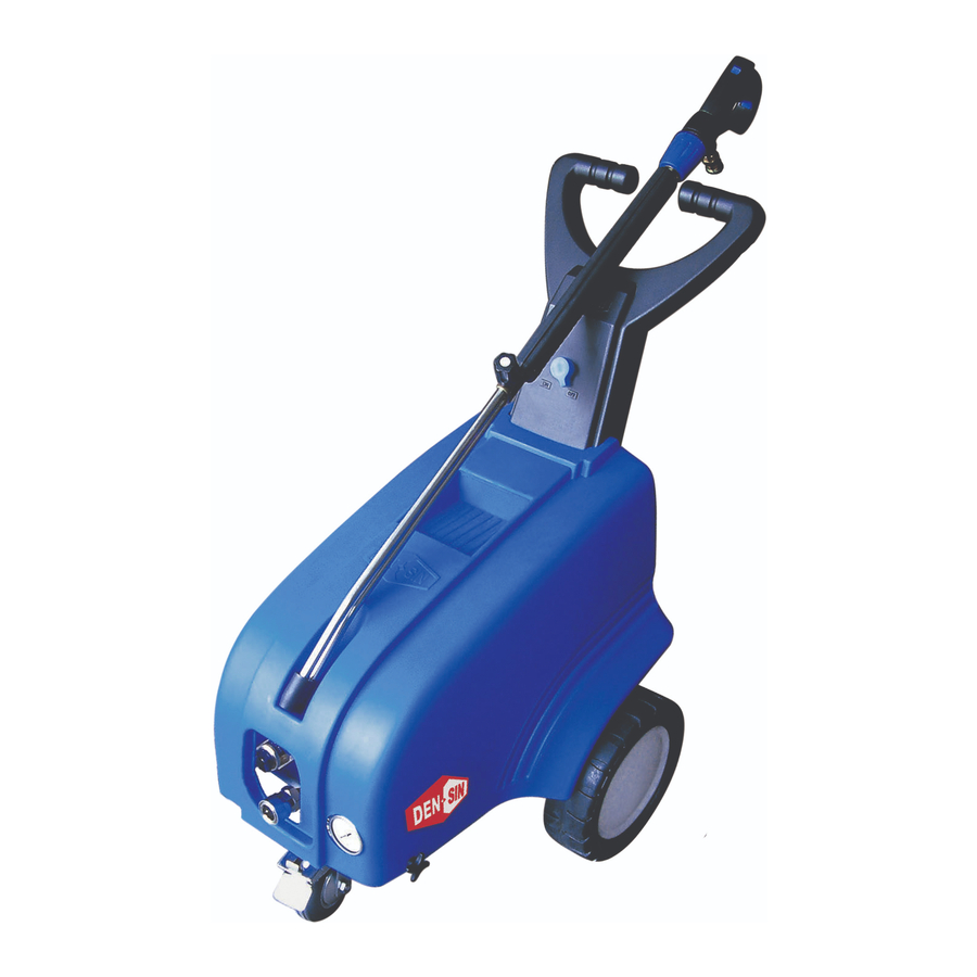
The Den-Sin C-110E is an industrial high-pressure cleaner. It operates at 110 bar pressure, has a flow rate of 11.7 liters per minute, and uses a 2.2 kW electric motor. It runs on 220 V, single-phase, 60 Hz power. The cleaner includes a 10-meter high-pressure hose and a high-pressure spray gun.


Need help?
Do you have a question about the C-110E and is the answer not in the manual?
Questions and answers
Den sin 110
The Den-Sin C-110E is an industrial high-pressure cleaner. It operates at 110 bar pressure, has a flow rate of 11.7 liters per minute, and uses a 2.2 kW electric motor. It runs on 220 V, single-phase, 60 Hz power. The cleaner includes a 10-meter high-pressure hose and a high-pressure spray gun.
This answer is automatically generated