Table of Contents
Advertisement
1. Introduction
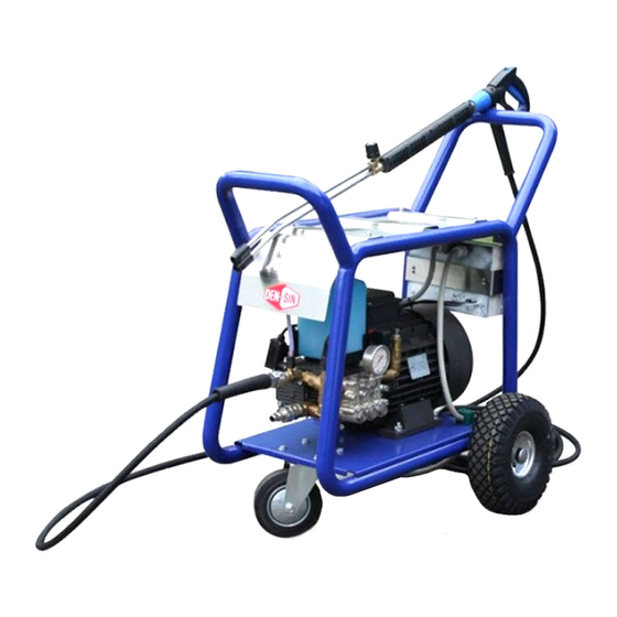
Congratulations on your purchase of the DEN-SIN High Pressure Cleaner.
Model: C-250E
Read this user manual before you start up your High Pressure Cleaner the first time.
This document or part of it may not be photocopied, or in any other way reproduced, or
translated to other languages without the prior written consent of DEN-SIN.
This machine is a High Pressure Cleaner producing water jet under high-pressure, which is
why severe injuries can occur if the safety precautions are not observed.
Therefore a full understanding of the contents of this instruction manual is required, in order
to prevent injuries to you, objects and persons nearby.
Safety
The following symbols are used in this manual to indicate procedures that if not followed,
may results in personal injuries or damage to equipment.
WARNING
practice which if not followed correctly could result in personal
injuries.
WARNING
CAUTION
practice which if not followed correctly could result in damage
to machine or other equipment.
CAUTION
NOTE
assist the reader carrying out the procedure or understanding the
text.
NOTE
Version 14: Apr 2018
Revision History
Revision
Change pump no.
Manual updating
Manual update, removal of CE declaration.
Manual Content Updating. Cable P/N Update
Manual Content Updating.
C-250E
Introduction
is used to alert the reader of procedures or
is used to alert the reader of procedures or
is used to highlight important information that may
R14
Rev.No.
10
11
12
13
14
Page 1
Advertisement
Table of Contents
Troubleshooting

Related Manuals for Den-Sin C-250E


Summary of Contents for Den-Sin C-250E
- Page 1 This document or part of it may not be photocopied, or in any other way reproduced, or translated to other languages without the prior written consent of DEN-SIN. This machine is a High Pressure Cleaner producing water jet under high-pressure, which is why severe injuries can occur if the safety precautions are not observed.
-
Page 2: Table Of Contents
Trigger / gun & assembly spare-parts list E250 ..............33 Repair Kit Trigger Gun ......................33 Electrical Box ........................34 Wiring diagrams ........................35 5. Warranty ..........................36 The information contained in this user guide is subject to change without notice. NOTE C-250E Page 2... -
Page 3: Getting Acquainted With Your High Pressure Cleaner
1. Getting acquainted with your High Pressure Cleaner Fast and efficient cleaning The DEN-SIN High Pressure Cleaners in the C-250E series enables you to get more cleaning done in less time. This series of DEN-SIN High Pressure Cleaners offers you high performance yet a compact design. -
Page 4: Unpacking
Connect the other end of the water supply hose to a potable water tap. Turn on tap. Connect to the public mains water supply in accordance to Notice regulations. C-250E Page 4... - Page 5 High Pressure Cleaner without sufficient potable water supply as it can cause cavitation and serious damage to internal pump parts. Do not let the machine CAUTION recycle the water (running with Spray-gun trigger not activated) for more than a minute. This can cause serious damage to the seals. C-250E Page 5...
-
Page 6: Machine Shut Down Procedure
Make sure lance is pointing downwards when doing this as pressure could cause injury. Once pressure is release, turn off water supply and disconnect inlet and outlet hose from machine. Dry the machine and store it. C-250E Page 6... -
Page 7: Operations
14) When pausing during operation, turned off the main switch of the machine. 15) Only use high-pressure hoses, connections and nozzles specified by DEN-SIN. 16) IMPORTANT – Do not use the machine in a possible explosive environment in accordance with EN-50014. -
Page 8: Safety And Protection Information
10) It is not allowed to connect this machine directly to a potable water supply. 11) If the machine is to be connected to potable water supply it is strictly necessary to fit the machine with a water break tank, in accordance with EN1717. C-250E Page 8... -
Page 9: Safety Devices
To restart the machine, simply press the trigger/ gun and the machine will start automatically. The timer is preset to 1.5 minutes - do NOT change the setting. DON’T C-250E Page 9... -
Page 10: Important Medical Information
Inform the doctor of the cause of the injury. Show this card to the doctor. DEN-SIN - a division of Nilfisk Pte Ltd. 05 Tuas Ave 2 Singapore 639445 Tel: +65 6268 1006 Fax: +65 62684916 MEDICAL ALERT... -
Page 11: Safety Precautions
They do NOT deflect direct jet impact. Therefore, an operator must take care never to point a water-jet either at themselves or other personnel. Hose protection- Protect user from high pressure water injuries incase hose connection is loose. C-250E Page 11... -
Page 12: Maintenance And Troubleshooting
To prevent electrical shock and safety to the user for wear and cracks Extend life span of the pump seals and Ensure coupling parts free of dirt to ensure maintaining correct pressure. long life of O-ring seals preventing water leaks. C-250E Page 12... -
Page 13: Troubleshooting
For any further inconveniences, not mentioned in this user guide or any damages of the machine, we strongly suggest you to make contact with your dealer for the repair or possible replacement of any original spare-parts. NOTE C-250E Page 13... - Page 14 4. Use a small probe to move the poppet up and down to assure that the valve is functioning properly and that no debris is stuck in the valve. (See Fig.3) 5. Using the mechanics pick remove the valve seat O-ring and inspect for any damage, replace if necessary. (See Fig. 4) Fig.3 Fig.4 C-250E Page 14...
- Page 15 1. Install the valve seat O-ring squarely into the bottom of the manifold. (See Fig.5) 2. Insert the valve assembly squarely into the port pushing it into the O-ring. (See Fig.6) Fig.5 Fig.6 3. Install the valve cap and torque to the proper specification. (See Fig.7) Fig.7 C-250E Page 15...
- Page 16 6. The low-pressure seal is located in the brass seal retainer. Using the mechanics pick go in between the seal and retainer, twist and pull, the seal will come out of the gland. (See Fig.13 & 14) 7. Remove the seal retainer O-ring with the mechanics pick. (See Fig.15) Fig.12 Fig.13 Fig.14 Fig.15 C-250E Page 16...
- Page 17 Fig.18 Fig.19 4. Install the retainer O-ring. (See Fig. 20) 5. Squarely seat the retainer into the head and push with even pressure until it snaps into position. (See Fig.21) Fig.20 Fig.21 C-250E Page 17...
- Page 18 4. Remove the plunger rod O-ring seal and split back-up ring with the mechanics pick. (See Fig. 24) 5. Remove brass slinger. At this point clean any thread locker that is left on the plunger rod and retaining nut threads. (See Fig. 25) Fig.24 Fig.25 C-250E Page 18...
- Page 19 4. Install the small copper washer on top of the plunger and place a small quantity of thread sealant in the thread. Install the plunger nut and tighten to the required torque. (See Fig. 29 & 30) Fig.30 Fig.29 C-250E Page 19...
- Page 20 D es c rip tio ns H e a d (F ig .3 4 ) P is t on N u t V a lve C ap In .lb s 1 33 1 0 6 4 4 2 K g. m /N .m C-250E Page 20...
-
Page 21: Available Accessories
NOZ0040 for 50/60Hz Repair Kits Part no.: Rotating Nozzle Repair Kit 700550305 Notice: Always state type of High Pressure Cleaner along with the part no.: when ordering accessories or spare-parts. ID-plate Refer to the identification plate on the machine: C-250E Page 21... -
Page 22: Chassis Assembly
5. Spare Parts Request Form Chassis assembly C-250E Page 22... -
Page 23: Chassis Assembly Spare-Parts List
700510005 Washer Flat M8 700510057 Nut M8 700520635 1 set Chemical Tank Holder (L/R) 1 set Unloader Assembly 700520667 Wheel Bushing SHOWN 700520325 Water Inlet Hose + Hose Nipple (Optional) Machine Model Pos: Part no.: Qty.: Description: C-250E Page 23... - Page 24 5. Spare Parts Request Form 700995661 C-250 50Hz 380~415V with Pneumatic Wheels 1-43-A 700995655 C-250 60Hz 440 V with Pneumatic Wheels 1-43-A C-250E Page 24...
- Page 25 5. Spare Parts Request Form Pump assembly C-250E Page 25...
-
Page 26: Pump Assembly Spare-Parts List
PUMP HEAD ASSEMBLY 700560125 RING 700560126 BEARING 700560127 OIL INDICATOR 700560128 SNAP RING 700560129 DISC 700560130 O-RING DIA 20,24 x 2,62 1-89 700560151 Pump Complete 50Hz 1-89 700560090 Pump Complete 60Hz Note: Parts Pos. may not appear in sequence C-250E Page 26... - Page 27 O-RING DIA 59,99 x 2,62 Oil seals O-RING DIA 106 x 3 (1 SET) SEAL SUPPORT RING DIA 18 GASKET Kit D – 700560138 PISTON GUIDE DIA 18 Water seals (Ø18) O-RING DIA 31,47 x 1,78 (1 SET) GASKET SEAL C-250E Page 27...
-
Page 28: Un-Loader Valve Assembly
5. Spare Parts Request Form Un-loader valve assembly C-250E Page 28... -
Page 29: Un-Loader Valve Assembly Spare-Parts List
700550025 CHEMICAL INJECTOR 700540026 QUICK COUPLING MALE OUTLET 700540771 ELBOW 1/2” M-F 700540249 NIPPLE 3/4" BSP - 1/2" NPT 700550004 DOWTY SEAL 3/8” 700540034 QUICK COUPLING FEMALE INLET 700540035 O-RING 700540036 HOSE NIPPLE 1-43 Unloader System Complete C-250E Page 29... -
Page 30: Repair Kit Unloader Valve
O-RING 1.78X15.6 2062 NBR 90 NERO DOWTY SEAL 1/2" VALVE MANIFOLD O-RING 2.62x15.88 NBR 70 NERO Kit F – 700540940 BANJO BOLT 1/2” (Banjo Bolt Kit) DOWTY SEAL 3/8” O-RING 2.62x12.37 NBR 70 NERO BANJO BOLT 3/8” C-250E Page 30... -
Page 31: Safety Valve Assembly
Safety valve assembly Safety valve assembly spare-parts list Pos: Part no.: Qty.: Description: 700540119 Body Safety Valve 3/8” 700540115 Pneumatic Ball 700540121 Piston 700540120 O-Ring 700540122 Spring Washer 700540124 Fitting Adjusting Screw 700510008 700540110 Safety Valve Complete C-250E Page 31... -
Page 32: Lance Assembly (Standard)
Lance D.B complete w/o nozzle 700550075 Nozzle 1504 50/60Hz 700550003 Quick Coupling Female High Pressure 700540491 O-Ring 700550004 Dowty Seal 3/8” 700551422 HOSE HP 10M+CPL+RL30 SET 1-18 700551472 LANCE D.B W/Q CPG + NOZ 1504* 50/60Hz * Not Shown C-250E Page 32... -
Page 33: Trigger Gun Assembly
Repair Kit Trigger Gun Part no.:/ Kit description Pos: Qty.: Individual components Part no.: Back Up Ring Piston, Stainless Steel O-Ring +Seat Kit G - 700551278 (Trigger Gun Repair Kit) O-Ring, Ø2.62x2.84 Ball, Stainless Steel O-Ring, Ø1.5x10 C-250E Page 33... -
Page 34: Electrical Box
(380-440V 50/60Hz) 700530154 Pressure Switch 45 Bar 700530155 Pressure Switch 25 Bar 700540114 T-Joint 3/8” M-1/4”F 700540117 T-Joint 3/8”M-F-F 700510136 Contra Nut 3/8” 700510007 Locknut M6 1-11 700530863 1 set Electrical Box Assembly (380-440V 50/60Hz) * Not Shown C-250E Page 34... -
Page 35: Wiring Diagrams
5. Spare Parts Request Form Wiring diagrams C-250E 380-440V with Auto Start Stop C-250E Page 35... -
Page 36: Warranty
Accessories or equipment furnished by DEN-SIN but manufactured by others, shall carry the warranty that its manufacturer has conveyed to DEN-SIN, and which may be passed on to the purchaser. The original warranty period of any article, which has been repaired or replaced by DEN-SIN, shall not thereby be extended.
Need help?
Do you have a question about the C-250E and is the answer not in the manual?
Questions and answers