
Related Manuals for Vallox 51 MV


Summary of Contents for Vallox 51 MV
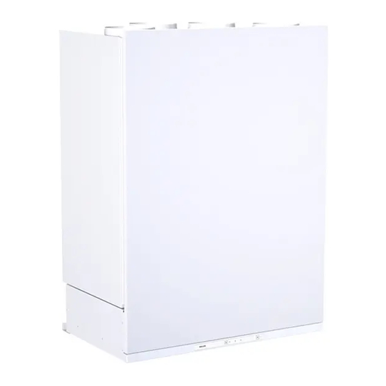
- Page 1 Model Document Vallox 51 MV D7597 Vallox 51K MV Valid from Type 26.03.2019 3750 3751 Updated 22.07.2019 Manual Ventilation units...
-
Page 2: Table Of Contents
Guarantee ........... 3 Vallox 51 MV / Vallox 51K MV ....... .22 Intended use . -
Page 3: Safety
Structural or electronic modifications or changes made to the software INTENDED USE All Vallox ventilation units have been designed to provide appropriate and continuous ventilation so as to present no threat to health and to maintain structures in good condition. -
Page 4: Safety Signs Used In The Instructions
INSTALLATION OPTIONS • Vallox 51 MV and 51K MV can only be mounted on the wall. There are two unit models, left- (L) and right-handed (R). In the NOTE right-handed version, outdoor air blows into the unit from the The standard right. -
Page 5: Changing The Ventilation Profile
Changing the ventilation profile Vallox 51 MV At home The Vallox 51 MV ventilation unit is controlled by using the MyVallox Control control panel. Press the left button of the control panel (see the Figure) repeatedly until the desired status is shown as the middle option on the display. -
Page 6: System Description
The selection button is roughly 2 cm to the left from the light switch. SYSTEM DESCRIPTION Internet 2. WLAN 3. Router 4. WLAN/LAN 5. Additional switch 6. Sensors MyVallox Cloud Vallox MV KNX bus module Modbus MyVallox Home MyVallox Control... -
Page 7: Connecting The Ventilation Unit To The Cloud Service
If this kind of alarm is noticed before fire damage, it can be simultaneously. acknowledged by pressing any of the cooker hood buttons. © Vallox Oy - All rights reserved... -
Page 8: Main Parts
MAIN PARTS Vallox 51 MV R model in the figure. In the L model, the parts are mirrored. Extract air fan Post-heating resistor Supply air fan Control panel Fine filter for supply air Carbon dioxide sensor (optional) Heat recovery cell... -
Page 9: Main Parts
Internal humidity sensor Automatic bypass damper Cooker hood Coarse filter for supply air Damper button Coarse filter for extract air Fan speed adjustment Post-heating resistor Light switch Control panel (Optional) Ceiling bushing for electric wires © Vallox Oy - All rights reserved... -
Page 10: Installation
REMOVAL OF CONDENSING WATER Vallox 51 MV The Silent Klick water seal is installed in the bottom pool of Vallox 51 NOTE MV. The condensing water tube is led from the water seal e.g. to the The Vallox Silent Klick water seal of the sink or to the floor drain. -
Page 11: Vallox 51K Mv
Instead, it must be installed in the condensing water tube so as to enable maintenance measures. There are approx. 2 mm wide holes at the rear of the bottom of the Vallox 51K MV ventilation unit marking the position where the condensing water tube must be installed. -
Page 12: Installation Of The Vallox Captura Cooker Hood
COOKER HOOD The minimum clearance between the bottom The Vallox Captura cooker hood is installed on the bottom of Vallox 51K MV. edge of the cooker hood and an electric Remove the plug from the feedthrough seal of the condensing stove is 426 mm. -
Page 13: Measuring And Adjusting The Air Flows Of The Ventilation Unit
Adjustment: • Cover the required number of holes in the damper with the magnetic strip that is delivered with the cooker hood. © Vallox Oy - All rights reserved... -
Page 14: Vallox 51 Mv, 51K Mv
A Supply air Extract air C Cooker hood extract air D Supply air fan Extract air fan R model in the figures. In the L model, the order of the ducts is mirrored. Vallox 51 Vallox 51K... -
Page 15: Dimensions And Duct Outlets
2. Exhaust air flowing outdoors from the Vallox 51K MV unit 3. Supply air from the unit to the apartment 4. Extract air from the apartment to the unit A double L model socket in this area © Vallox Oy - All rights reserved... -
Page 16: Maintenance
CHANGING THE FILTERS in top condition, giving the best results. To select and order filter packages, The Vallox ventilation unit has three filters: please go to: https:// valloxsuodattimet.fi • Coarse filter for supply air filters insects, heavy pollen and other relatively large foreign objects out of the outdoor air. -
Page 17: Cleaning The Heat Recovery Cell
Water must at all times condensing water outlet in the bottom pool are not clogged. To be kept out of the check this, pour some water into the pool. Clean as required. electrical system. © Vallox Oy - All rights reserved... -
Page 18: Cleaning The Fans
Disconnect the ventilation unit from the mains electricity them. Handle the fan supply. blades carefully. 2. Undo the door screws to open the door of the Vallox It is recommended that ventilation unit. the fans be cleaned by 3. Lift the door off. -
Page 19: Vallox 51K Mv
NOTE! Ensure that the locking device points downwards. Removing the filter Light Mounting the filter The cooker hood has a long-lasting LED lighting module. If the light is not working, contact a servicing company. © Vallox Oy - All rights reserved... -
Page 20: Technical Specifications
TECHNICAL SPECIFICATIONS VALLOX 51 MV Product title Product number HVAC code Vallox 51 MV R 4105064 7912132 Vallox 51 MV L 4105063 7912134 Air volumes Fans Supply air 47 dm³/s, 100 Pa Supply air 0.035 kW 0.35 A EC Extract air 51 dm³/s, 100 Pa... -
Page 21: Air Flows And Sound Values
, dB(A) Vallox 51 MV, Vallox 51K MV (no standard extract air flow through the hood in the kitchen) Sound pressure level coming through the envelope of the unit in the room in which it is installed (10m² sound absorption) -
Page 22: Internal Electrical Connection
INTERNAL ELECTRICAL CONNECTION Vallox 51 MV / Vallox 51K MV Internal electrical connection Vallox 51 MV / Vallox 51K MV 1 2 3 4 5 AHS S/E RH% 230V 50Hz 130°C 90°C MB_A External Modbus A signal Supply air fan... -
Page 23: External Electrical Connection
POSITION OF THE DAMPER: DAMPER CLOSED = CONTACT OPEN 3 POTENTIAL FREE DAMPER OPEN = CONTACT CLOSED CONTACT DATA 24VDC/5A Vallox 51K MV / Valloplus 180K MV GUARD FUNCTION CONTACT DATA Connection card © Vallox Oy - All rights reserved... -
Page 24: External Electrical Connection
EXTERNAL ELECTRICAL CONNECTION Vallox 51 MV MyVallox MyVallox transmitter transmitter Potential-free contact Potentiaalivapaa kärkitieto data 24VDC. Can be 24VDC. Voidaan ohjelmoida programmed to display MyVallox MyVallox MyVallox information such as MyVallox näyttämään esimerkiksi Ethernet connection and Ethernet -liitäntä ja Control... -
Page 25: External Electrical Connection
D/I1 = Digitaalinen tulo 1 Voltage 24 VDC External temperature sensor connector D/I2 = Digitaalinen tulo 2 11V1 = 11,1V voltin käyttöjännite AN/I = Analoginen sisääntulo 0-10Vdc © Vallox Oy - All rights reserved RM/I = 24V releen sisäänmeno RM/O = 24V releen ulostulo... -
Page 26: External Electrical Connection For Controlling The Mlv Multi Duct Radiator
EXTERNAL ELECTRICAL CONNECTION FOR CONTROLLING THE MLV MULTI DUCT RADIATOR 24 VDC relay/contactor Distribution for controlling the board pump and solenoid valve +24VDC Ethernet connection on top of the unit RJ45 Female MLV control Plug connection VENTILATION UNIT INTERNAL ELECTRICAL CONNECTION +24V +24V voltage (DC) -
Page 27: Mvl Multi Duct Radiator Operation Chart
In this case, the pump and the solenoid NOTE: COOLING valve can be controlled using a Vallox MV ventilation unit, The value set for the and no separate thermostats are needed. -
Page 28: Exploded View And Parts List
4104020 949033 the lock nut of the door screw) panel Door 4106304 Fan attenuation grid 4104868 Water seal Vallox Silent Klick 3494701 Post-heating resistor, R model 4106543 Plastic screw 990151 Upper support for HR cell 4103238 Post-heating resistor, L model... -
Page 29: Vallox 51K Mv
Cover plug 4105656 white Lock nut of the door screw Front panel assembly 4104020 (supplied together with the door 990715 2131900 stainless steel screw) Fan attenuation grid 4104868 Coarse filter for extract air 4103284 © Vallox Oy - All rights reserved... -
Page 30: Conformity Certificates
CONFORMITY CERTIFICATES... - Page 31 © Vallox Oy - All rights reserved...
- Page 32 Vallox Oy | Myllykyläntie 9-11 | 32200 LOIMAA | FINLAND Customer service +358 10 7732 200 | Aftersales +358 10 7732 270 © Vallox Oy - All rights reserved...
Need help?
Do you have a question about the 51 MV and is the answer not in the manual?
Questions and answers