Advertisement
Quick Links
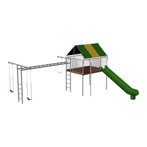
MODEL CH35
_____ 4-clubhouse legs
_____ 1- Plastic lumber package
_____ 1-CH/PH Fire Pole
_____ 1-8' Full Barrier
_____ 1-8' Two Opening Barrier
_____ 1-6' Full Barrier
_____ 1-6' One Opening Barrier
_____ 1-8' 4 rung ladder, adj. sleeves
_____ 1-8' 4 rung ladder, adj. sleeves (Drilled)
_____ 1-12'6" horizontal ladder
_____ 1-5' 6" x 2⅜" top rail
_____ 1-9' x 2⅜" top rail
_____ 1-10' plastic Rocket slide ______________
_____ 1 - Rocket Slide Foot
_____ 2 - Canopy side rails
_____ 1 - Canopy middle upright
_____ 4 - Floor Joists
_____ 1 - Floor Joist End
_____ 1 - Floor Joist End Drilled
_____ 2-5" strap seats ______________
_____ 1-trapeze bar ________________
_____ 6-2 ⅜" Brass Bushing Hangers
_____ 2-3½' chains _______________
_____ 4-5½' chains _______________
_____ 1 - Steering wheel ____________________
_____ 1 - Steering wheel hardware pkg
_____ 1 - Telescope _______________
_____ 1 - Telescope hardware pkg
_____ 1 - Canopy kit bolt pack
_____ 1 - CH Canopy tarp _______________
_____ 2 - Canopy center T attachments
NAME: __________________________________
INV #: __________________________________
DATE: ___________________________________
BOX PULLED BY: __________________________
STAGED BY: ______________________________
SHIPPING PIECES: 28
WEIGHT: 1150 lbs.
_____ 1-clubhouse legs bolt pack
_____ 1-135 self drilling screws bolt pack
_____ 1 CH barrier bolt pack
_____ 1-spring clip 12 Pack
_____ 1- HL Bolt Pack
_____ 4- 2 ⅜" plastic plugs
_____ 1- Can of ____________ touch up paint
_____ Instructions
Advertisement

Related Manuals for Component Playgrounds CH35


Summary of Contents for Component Playgrounds CH35
- Page 1 MODEL CH35 NAME: __________________________________ INV #: __________________________________ DATE: ___________________________________ BOX PULLED BY: __________________________ STAGED BY: ______________________________ SHIPPING PIECES: 28 WEIGHT: 1150 lbs. _____ 4-clubhouse legs _____ 1- Plastic lumber package _____ 1-CH/PH Fire Pole _____ 1-clubhouse legs bolt pack _____ 1-8’ Full Barrier _____ 1-135 self drilling screws bolt pack _____ 1-8’...
- Page 6 PLEASE READ AND UNDERSTAND ALL INSTRUCTIONS BEFORE BEGINNING The CH35 can be installed as a one day project. The normal time required to install the CH35 is about 6 – 7 hours for a two to four man crew. This time requirement will vary dependent upon the composition of the soil and the speed of the installers.
- Page 7 Be certain that there is ample space around the structure to safely enter or exit the slides and climbers. In a standard configuration, the CH35 minimum required Play Space is: 33’ x 26’. If you have modified the climb- ers or slides you will need to consider these modifications as you determine the play space you will need.
- Page 8 1.c. Place the 5’ 6” top rail, 12’ 6” horizontal ladder, and 9’ top rail in the play space as shown below. Mark where the ladder holes will need to be dug. Remove the top rails and horizontal ladder and dig the ladder hole to the measurements specified below.
- Page 9 **Important Notice! Please read and understand prior to proceeding** Pre-Assembly: Assembling the Club House Floor Joists 2.a. Locate the Floor Joist End with the four holes in it as shown below and determine which holes you will be using for your particular swing set configuration. This is the end that will bolt to the vertical ladder. 18”...
- Page 10 2.c. Position assembled deck frame on the ground as shown below. Mark the holes for the Club House Legs. Dig the holes to the specifications below. Hole size for Club House Legs is 18” wide by 16” deep. With top rail in place, place deck frame square with the top rail overlapping 24”.
- Page 11 Assembling ladders and attaching to deck support structure 3.a. Make a mark 108” up from the bottom of the ladder onto each ladder rail. Move the adjustable sleeves to these marks and position them to receive the horizontal ladder by turning them to point at a 90 degree angle (towards what will become the inside of the Horizontal ladder section of the structure.) Secure the set screws.
- Page 12 3.c. The vertical ladders should be positioned on the ground with the bottom of the ladder placed just over the hole where it will finally stand. (Please make sure that the drilled ladder is placed at the end that is next to the Club House Platform).
- Page 13 Assembling the Platform Support Structure 4.a. On a hard flat surface such as a drive way, install one piece of the plastic lumber at the front of the platform and one at the back of the platform. The leading edge of the lumber should be flush with the edge of the square tubing.
- Page 14 4.b. Having pre-assembled the floor joist system, it is now best to have at least three people to assemble the Club House Legs to the floor Joists. Insert all four legs. Then insert and secure one set screw into each leg to hold them in place.
- Page 15 4.d. Attach the Platform Support Structure to the vertical ladder using the 5” carriage bolts pushed through the ladder and through the support structure as shown, attaching platform to 8’ vertical ladder. You may need to adjust the depth of the individual holes to make the platform structure and the ladder level up to each other and to make the holes line up.
- Page 16 4.f. Insert toprails as shown below to marks previously made. Secure them with set screws. 4.g. Level the Club House platform and the swing structure. If you are assembling this structure in one day, disregard this step. When you are satisfied that the structure is level, mix and pour the concrete according to the package directions.
- Page 17 Installing the Plastic Lumber 5.a. With the first two boards secured into place, lay out the remaining boards onto the support structure. Even- ly space the boards as shown in the diagram shown below. Beginning at one end, it works best to secure each board in turn using one screw at each end of the board to secure it to the support structure, repeating this process until all of the boards are attached to the support structure.
- Page 18 Assembling the Barriers 6.a. Position the Barriers onto the platform and connect the corners together at 45 degree angles as shown be- low. Use two of the eight sets of panel clamps with the 3/8” x 2” carriage bolt and 3/8” hex nut that are pro- vided at each corner.
- Page 19 Assembling the Canopy Kit 7.a. Attach the canopy ridge pole brackets to the center of both of the six foot barriers with panel clamps as shown below. 7.b. Insert the canopy ridge pole into the brackets previously attached to the barriers. Note: Barrier configuration shown here is generic and does not necessar- ily represent the barriers or configuration you may have purchased.
- Page 20 7.c. Insert canopy supports in through the sleeves of the canopy as shown below. 7.d. Attach canopy to barriers as shown below. 1. Attach the first canopy support us- ing panel clamps. 2. Pull canopy tight and attach second canopy support us- ing panel clamps.
- Page 21 Attaching Climbers and Slides 8.a. Plastic Slide. The slide is simply placed into position on the Clubhouse Platform. Stand back to look at the slide, making sure that it is placed straight and square to the platform. Be sure that there is a minimum of 5’ at the bottom of the slides to allow safe exit space.
- Page 22 Double Check and Secure: Make sure to plug the open ends of the floor joist and the top rail with the plugs provided. Double check and secure any loose set screws or nuts and bolts and enjoy your Component Play- ground.
-
Page 24: Installation Instructions
INSTALLATION INSTRUCTIONS Steering Wheel Steering Wheel Bracket with welded bolt. Push two 1-3/8” Plugs in the ends 3/8” Nyloc 7/16” Plastic Pivot Washer Pivot Plug Assemble Steering Wheel as shown above. Then attach Bracket to the Barrier with panel clamps and 3/8”... - Page 25 INSTALLATION INSTRUCTIONS Telescope Using a small phillips head screw driver and a 1/4” socket. Use 4-40 x 3/4” Machine Screws and 4-40 Nyloc Nuts to attach one side of the plastic ring to the Bracket with welded washer. Place the Base of the Telescope under the lip of the plastic ring and attach the other half of the plastic ring.
- Page 26 While every attempt is made by Component Playgrounds to ensure the highest degree of safety in all of our equipment, we cannot guarantee freedom from injury. The user assumes all risk of injury due to use. All...
- Page 27 We hope that you and your family will enjoy many of hours of great family fun while using your Component Playgrounds Products. We appreciate your business. Our goal is to provide safe, durable and fun products using the best materials available. Your product should be mostly maintenance free.
- Page 28 When your equipment is built, Component Playgrounds will repair this damage using a cold galvanizing compound spray along with a top coat of silver aluminum. This is a time tested and durable process. However, when you are inspecting your playground equipment, if...
- Page 29 To Help Prevent Injuries from Falls & other Hazards Never attach, or allow children to attach the following items to your swing set: Ropes, jump ropes, clotheslines, pet leashes or any similar type of item to your swing set. Any item such as these may present a strangulation hazard.
- Page 30 Limited Lifetime Warranty Component Playgrounds works to build heavy duty products that will stand up to the heavy use of active children. You can trust Component Playgrounds because of the way we design and build our products. We make products that are simple to own, and easy to maintain.
Need help?
Do you have a question about the CH35 and is the answer not in the manual?
Questions and answers