Advertisement
Quick Links
What's in the box?
The package includes the following items:
PISO-P32C32U(-5V)
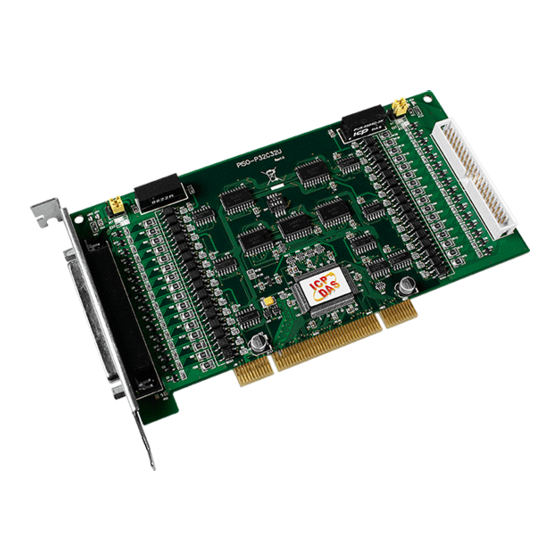
PISO/PEX-P32C32 Card x 1
CA-4037B Cable x 1
Related Information
For more detailed information related to the user manual and
software for UniDAQ Driver & SDK:
http://ftp.icpdas.com/pub/cd/iocard/pci/napdos/pci/unidaq/
For more detailed information related to the hardware settings for
PISO/PEX-P32C32 Series Card:
http://ftp.icpdas.com/pub/cd/iocard/pci/napdos/pci/piso-dio/manual/
DN-37 and CA-3710 Cable Page (optional):
Technical support:
PISO-P32C32U(-5V)/
PEX-P32C32
or
service@icpdas.com
PEX-P32C32
Quick Start
Quick Start x 1 (This Document)
CA-4002 D-Sub Connector x 2
v1.4, Dec. 2018
P1
Advertisement

Related Manuals for ICP DAS USA PISO-P32C32U-5V


Summary of Contents for ICP DAS USA PISO-P32C32U-5V
- Page 1 PISO-P32C32U(-5V)/ PEX-P32C32 Quick Start v1.4, Dec. 2018 What’s in the box? The package includes the following items: PISO-P32C32U(-5V) PEX-P32C32 PISO/PEX-P32C32 Card x 1 Quick Start x 1 (This Document) CA-4037B Cable x 1 CA-4002 D-Sub Connector x 2 Related Information ...
-
Page 2: Jumper Settings
Appearance LED3: DO indicator LED1: DO indicator Jumper JP2 LED4: DI indicator LED2: DI indicator Jumper JP1 LED1 LED2 LED3 LED4 DC/DC1 DC/DC2 1 2 3 4 DI channel 16-31 Card ID Switch DI channel 0-15 ... - Page 3 Installing a PISO/PEX-P32C32 1) Power off the PC. 2) Remove all covers from the Computer. 3) Carefully insert the PISO/PEX-P32C32 Series Card into PCI/PCIe slot. 4) Replace the PC Covers. 5) Power on the PC. 6) Download or locate the Windows driver. ...
-
Page 4: Pin Assignments
Pin Assignments Extension Cable (CA-4037B): DB-40-Pin conversion DB-37-Pin NOTES: 1. Ext.GND: External Power Ground 2. Ext.PWR: External Power Input 3. N.C.: None Connect 4. For detailed information abuout the DI and DO wiring note, refer to Section 2.3 “Isolated DI Architecture” and Section 2.4 “Isolated DO Architecture”... - Page 5 5) Connect the External Power Supply GND to COM1B (Pin19) and Ext.GND0 (Pin1/Pin20), see Figure 1-2. NOTE: The PISO-P32C32U-5V suggests input voltage range +5 to +12V (Logic high). (Higher voltage over the limitation will cause the hardware damage.) Technical support:...
- Page 6 DN-37 I/O Wiring 20 21 22 23 24 25 26 27 28 29 30 31 32 33 34 35 36 10 11 13 14 15 16 ----------------------------------------------------------------------------------------------- Figure 1-2: The PISO-P32C32U-5V wiring: External CON1 Power Supply (+5V ~ +12V) CA-3710...
- Page 7 Testing your PISO/PEX-P32C32 1) Launch the UniDAQ Utility software. The UniDAQ Utility will be placed in the default path “C:\ICPDAS\UniDAQ\Driver” after completing installation. Double-Click 2) Confirm that PISO-P32C32 Series Card has been successfully installed in the Host system. Note that the device numbers start from 0.
- Page 8 4) Click the “Digital Output” tab. 5) Select “Port0” from the “Port Number” drop-down menu. 6) Click the DO channels 0, 2, 4 and 6 buttons. Port0: DO0-7 Port1: DO8-15 Port2: N.C. Port3: N.C. 7) Click the “Digital Input” tab. 8) Select “Port0”...