
Subscribe to Our Youtube Channel
Related Manuals for Baxi Platinum BC iPlus V200 Smart 4.5


Summary of Contents for Baxi Platinum BC iPlus V200 Smart 4.5
- Page 1 Installation, User and Service Manual Reversible air/water "Split Inverter" heat pump Platinum BC iPlus V200 Smart MIC V200...
-
Page 2: Table Of Contents
Contents Contents Safety instructions and recommendations ..............6 Safety . - Page 3 Contents 5.6.6 Checking the heating circuit ............. .39 Filling the installation .
- Page 4 Contents 7.3.12 Reducing the noise level of the outdoor unit ..........79 7.3.13 Detecting an additional or replacement PCB .
- Page 5 Contents 13.2.1 AWHP 4.5 MR ............... 126 13.2.2 AWHP 6 MR-3 .
-
Page 6: Safety Instructions And Recommendations
1 Safety instructions and recommendations Safety instructions and recommendations Safety Operation Danger This appliance can be used by children aged from 8 years and above and persons with reduced physical, sensory or mental capabilities or lack of experience and knowledge if they have been given supervision or instruction concerning use of the appliance in a safe way and understand the haz... -
Page 7: General Instructions
1 Safety instructions and recommendations Domestic wa Caution The pressure limiter device (safety valve or safety unit) must be regularly operated in order to remove limescale deposits and ensure that it is not blocked. A pressure limiter device must be fitted to a discharge pipe. As water may flow out of the discharge pipe on the pressure limiter device, the pipe must be kept open to the air, in a frost-free environment, and at a continuous downward gradi... -
Page 8: Refrigerant Safety
1 Safety instructions and recommendations Refrigerant safety Warning Refrigerant fluid and pipes: Use only R410A refrigerant fluid to fill the installation. Use tools and pipe components especially designed for use with R410A refrigerant fluid. Use copper pipes deoxidised with phosphorus to carry the refrigerant fluid. -
Page 9: Hydraulic Safety
1 Safety instructions and recommendations Hydraulic safety When making the hydraulic connection, it is imperative that the standards and corresponding local directives be respected. If radiators are connected directly to the heating circuit: install a differential valve between the indoor module and the heating circuit. Fit drainage valves between the indoor module and the heating circuit. -
Page 10: Specific Instructions For Service, Maintenance And Breakdowns
1 Safety instructions and recommendations Specific instructions for service, maintenance and breakdowns Maintenance work must be carried out by a qualified professional. Only a qualified professional is authorised to set, correct or replace the safety devices. Before any work, switch off the power supply to the heat pump, the indoor module and the electrical back-up. -
Page 11: Symbols Used
3 Information on the electrical back-up: power supply and maximum output 4 Before installing and commissioning the appliance, carefully read the instruction manuals provided 5 The symbol indicates compatibility with BAXI CONNECT TXM. 6 Dispose of used products in an appropriate recovery and recycling structure MW-3000555-02 Symbols used on the appliance Fig.2... - Page 12 2 Symbols used 3 3/8" refrigerant fluid connection – liquid line 6 Domestic cold water inlet 4 5/8" refrigerant fluid connection – gas line 7 System A flow 5 Domestic hot water flow 8 System A return 7654506 - v06 - 19112019...
-
Page 13: Technical Specifications
3 Technical specifications Technical specifications Homologations 3.1.1 Directives This product complies with the requirements of the following European Directives and Standards: Pressure Equipment Directive 2014/68/EU Low Voltage Directive 2014/35/EU Generic standard: EN 60335-1 Relevant standards: EN 60335-2-40, EN 60335-2-21 Electromagnetic Compatibility Directive 2014/30/EU Generic standards: EN 61000-6-3, EN 61000-6-1 Relevant Standard: EN 55014 This product conforms to the requirements of European Directive... -
Page 14: Heat Pump Weight
3 Technical specifications Limit operating temperatures AWHP 4.5 MR AWHP 6 MR-3 AWHP 8 MR-2 Water in cooling mode +7 °C / +25 °C +7 °C / +25 °C +7 °C / +25 °C Outdoor air in cooling mode +10 °C/+46 °C +7 °C/+46 °C +7 °C/+46 °C Tab.4... -
Page 15: Domestic Hot Water Tank
3 Technical specifications Tab.9 Outdoor unit Data Unit AWHP 4.5 MR AWHP 6 MR-3 AWHP 8 MR-2 Weight 3.2.3 Domestic hot water tank Tab.10 Technical specifications primary circuit (heating water) Specification Unit Value Maximum operating temperature with electrical back-up °C Maximum operating temperature with solar circuit option °C Minimum operating temperature... - Page 16 3 Technical specifications Product name Platinum BC Platinum BC Platinum BC iPlus V200 iPlus V200 iPlus V200 Smart 4.5 Smart 6 Smart 8 Declared capacity for heating for part load at an in door temperature of 20 °C and outdoor temperature = -7 °C = +2 °C = +7 °C...
-
Page 17: Sensor Specifications
3 Technical specifications Product name Platinum BC Platinum BC Platinum BC iPlus V200 iPlus V200 iPlus V200 Smart 4.5 Smart 6 Smart 8 Water heating energy efficiency ƞ 133.00 130.00 123.00 Daily fuel consumption 0.000 0.000 0.000 fuel Annual fuel consumption Prated is equal to the design load for heating Pdesignh , and the rated heat output of a supplementary heater Psup is (1) The rated heat output sup(Tj) . -
Page 18: Circulating Pump
3 Technical specifications 3.2.6 Circulating pump Important The benchmark for the most efficient circulating pumps is EEI ≤ 0.20. Main circulating pump Fig.4 Pressure available (circuit A) The main circulating pump in the indoor module is a variable speed pump. It adapts its speed to the distribution network. -
Page 19: Dimensions And Connections
3 Technical specifications Dimensions and connections 3.3.1 Connection plate Fig.7 0-40 mm MW-1001613-2 1 Wall bracket * Drilling dimensions 2 Oscillating arm 7654506 - v06 - 19112019... -
Page 20: Indoor Module
3 Technical specifications 3.3.2 Indoor module Fig.8 Dimensions and connections of the indoor module 348.5 1949 244.5 194.5 1 2 34 5 6 7 8 78.5 0-20(a) 1 Heating circuit B return (option) or solar circuit flow 5 Domestic hot water outlet G3/4 (option) 6 Domestic cold water inlet G3/4"... -
Page 21: Awhp 4.5 Mr
3 Technical specifications 3.3.3 AWHP 4.5 MR Fig.9 (417.5) 417.5 10 X 21 MW-1000430-1 1 1/4" refrigerant fluid connection 2 1/2" refrigerant fluid connection 3.3.4 AWHP 6 MR-3 Fig.10 404.5 23.2 22.3 193.5 154.5 MW-1000919-1 1 1/4" refrigerant fluid connection 2 1/2"... -
Page 22: Awhp 8 Mr-2
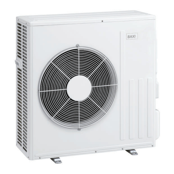
3 Technical specifications 3.3.5 AWHP 8 MR-2 Fig.11 MW-M001442-2 1 3/8" refrigerant fluid connection 2 5/8" refrigerant fluid connection 7654506 - v06 - 19112019... -
Page 23: Electrical Diagram
3 Technical specifications Electrical diagram Fig.12 SOLAR Sensor Solar Panel SENSOR TARGET 7724253 Sensor Solar Tank 7714999 7724255 PUMP SENSOR LIQUID 7717996 HPC-01 FUSE 7717840 WATER SENSORS 7699154 7622563 7699154 PUMP A 7682206 7715217 EHC-06 BLUETOOTH ACI-BDR 7715087 7717998 FUSE FUSE SCB-04 7714998... - Page 24 OUTDOOR UNIT Outdoor unit PUMP A / PUMP B Circulating pump A/Circulating pump B R-Bus (Room unit) BAXI CONNECT TXM connected room thermostat, on/off thermostat or OpenTherm thermostat Safety thermostat Safety thermostat SCB-04 PCB for controlling a second heating circuit...
-
Page 25: Description Of The Product
4 Description of the product Description of the product Main components Fig.13 MIC V200 1 Air vent 2 Electronic pressure gauge 3 Domestic water circuit safety valve (7 bar) 4 Electric panel 5 User interface 6 ON/OFF button 7 Flow meter 8 Plate heat exchanger (condenser) 9 12 L expansion vessel 10 Magnesium anode (or optional titanium anode) - Page 26 4 Description of the product Fig.14 MIC V200 with second circuit option 1 Air vent 2 Electronic pressure gauge 3 DHW circuit safety valve 4 Electric panel 5 User interface 6 ON/OFF button 7 Flow meter 8 Plate heat exchanger (condenser) 9 Expansion vessel 10 Magnesium anode (or optional titanium anode) 11 Mechanical pressure gauge...
-
Page 27: Control Panel Description
4 Description of the product Fig.16 Position of the PCBs 1 EHC–06 central unit PCB: control system for the heat pump and the first heating circuit (direct zone) 2 Position for an optional control system PCB: manages a second heating circuit or a solar circuit 3 HPC–01 PCB: PCB for interface with the outdoor unit 4 Space for an optional ACI BDR PCB for a titanium anode 5 Position of the Bluetooth card at the rear of the control panel... - Page 28 4 Description of the product Status of the Compressor Fig.20 Steady symbol: compressing running Operating modes Fig.21 Steady symbol: heating function enabled Flashing symbol: heating production running Steady symbol: domestic hot water function enabled Flashing symbol: domestic hot water production running Heating or cooling function disabled Domestic hot water function disabled Hydraulic pressure in the system...
- Page 29 4 Description of the product Display of PCB names Fig.25 The name of the PCB for which the parameters are displayed is scrolling across the screen on 3 characters. Fig.26 Central unit EHC–06 PCB: direct circuit and domestic hot water ...EHC / --06...
-
Page 30: Schematic Diagram
4 Description of the product Schematic diagram Fig.31 Indoor module with one heating circuit MW-3000700-01 A1 Domestic hot water outlet A4 Direct heating circuit A flow A2 Domestic cold water inlet D Disconnector A3 Direct heating circuit A return 7654506 - v06 - 19112019... - Page 31 4 Description of the product Fig.32 Indoor module with two heating circuits (second circuit optional) MW-3000699-01 A1 Domestic hot water outlet B1 Mixed heating circuit B flow A2 Domestic cold water inlet B2 Mixed heating circuit B return A3 Direct heating circuit A return D Disconnector A4 Direct heating circuit A flow 7654506 - v06 - 19112019...
- Page 32 4 Description of the product Fig.33 Indoor module with one optional solar circuit Bu er tank MW-3000698-2 E Solar circuit S1 Solar circuit heating return A1 Domestic hot water outlet S2 Solar circuit heating flow A2 Domestic cold water inlet Buffer tank Solar circuit buffer tank A3 Direct heating circuit A return D Disconnector...
-
Page 33: Installation
5 Installation Installation Installation regulations Warning The components used for the connection to the cold water supply must comply with the prevailing standards and regulations in the country concerned. Caution Installation of the heat pump must be done by a qualified professional in accordance with prevailing local and national regulations. -
Page 34: Data Plate On The Indoor Module
5 Installation 5.3.1 Data plate on the indoor module Fig.34 The data plate of the indoor module is located on the top of the appliance. A second data plate is affixed to the inside of the front panel. 5.3.2 Data plate on the outdoor unit Fig.35 MW-6000694-1 Respecting the distance between the indoor module and the outdoor unit... -
Page 35: Allowing Sufficient Space For The Indoor Module
5 Installation 2. Install the heat pump's indoor module on a solid, stable structure capable of bearing the weight of the heat pump when full of water and fitted with its various accessories. 3. Install the indoor module as close as possible to the draw-off points in order to minimise energy losses through the pipes. -
Page 36: Positioning The Indoor Module
5 Installation 5.5.5 Positioning the indoor module Fig.39 Installation of the connection plate Before installing the indoor module, position the connection plate supplied separately. Follow the instructions supplied with the plate. MW-1001529-1 Fig.40 Fitting the indoor module Fitting of the indoor module is facilitated by 2 castor wheels attached to the lower section. -
Page 37: Hydraulic Connections
5 Installation Fig.42 1. Detach the precut attachment in the top panel. 2. Secure the attachment against the wall using the screw and plug provided in the accessories bag. Hydraulic connections 5.6.1 Special precautions for the connection of the heating circuit When making the connection, it is imperative that the standards and corresponding local directives be respected. -
Page 38: Connecting The Various Circuits
5 Installation A disconnector A 7 bar safety valve An evacuation pipe A thermostatic mixing valve Isolation and venting valves for maintenance operations Connecting the domestic water: Comply with local standards and directives. Install a water drain in the boiler room. Use components that comply with the applicable standards and regulations in the country concerned. -
Page 39: Setting The Thermostatic Mixing Valve
5 Installation Fig.45 5. Observe the minimum dimension for condensate outflow. If the condensate collector hose does not follow a continual downward >1%(1cm/m) gradient, use a lift pump. 217mm MW-3000737-01 5.6.5 Setting the thermostatic mixing valve A thermostatic mixing valve is integrated into the domestic hot water flow pipe to limit the risk of being scalded. -
Page 40: Filling The Installation
5 Installation Filling the installation 5.7.1 Cleaning and flushing the installation Flushing new installations and installations less than 6 months Before filling the heating installation, it is essential to remove any debris (copper, caulking, soldering flux) from the installation. 1. Clean the installation with a powerful universal cleaner. 2. -
Page 41: Fill The Domestic Hot Water Circuit
< 1 °f 7 - 15 Total water hardness °dH 4 - 8.5 mmol/l 0.7 - 1.5 If water treatment proves necessary, Baxi recommends the following manufacturers: Cillit Climalife Fernox Permo Sentinel 5.7.3 Fill the domestic hot water circuit 1. -
Page 42: Selecting The Location Of The Outdoor Unit
5 Installation Fig.47 1. Respect the minimum positioning distances of the outdoor unit from the wall. Tab.23 Minimum distances in mm AWHP 4.5 MR 1000 AWHP 6 MR-3 1000 AWHP 8 MR-2 1000 5.8.2 Selecting the location of the outdoor unit Fig.48 To ensure the outdoor unit operates correctly, its location must meet certain conditions. -
Page 43: Choosing The Location Of A Noise Abatement Screen
5 Installation 5.8.3 Choosing the location of a noise abatement screen When the outdoor unit is too close to neighbours, a noise abatement screen can be fitted to reduce noise pollution. Fig.49 MW-C000373-1 1. Locate the noise abatement screen as close as possible to the source of noise whilst allowing for the free circulation of air in the exchanger on the outdoor unit and maintenance work. -
Page 44: Installing The Outdoor Unit On The Ground
5 Installation 5.8.5 Installing the outdoor unit on the ground Fig.51 When installing on the ground, a concrete base must be installed, with no rigid connection to the building served to avoid the transmission of vibrations. Position a rubber floor support. The data plate must be accessible at all times. -
Page 45: Connect The Refrigerant Connections To The Indoor Module
5 Installation 5.9.2 Connect the refrigerant connections to the indoor module Fig.52 Fitting refrigerant hoses To facilitate the refrigeration connections, hoses are supplied with the connection plate. Position these hoses before fitting the indoor module in place. Caution For connection at the top, use the hose kit (2300 mm) from the package EH978. -
Page 46: Connecting The Refrigerant Connections To The Outdoor Unit
5 Installation 5. Tighten the connections, observing the given tightening torques. Apply refrigerant oil to the beaded parts to facilitate tightening and improve the seal. Tab.25 Tightening torque applied External diameter of External diameter of Torque load (N.m) the pipe (mm/inch) the cone fitting (mm) 6.35 - 1/4 14 - 18... -
Page 47: Testing The Leak-Tightness Of The Refrigerant Connections
5 Installation 5.9.4 Testing the leak-tightness of the refrigerant connections Fig.57 1. Remove the plugs from the stop valves A and B / C. 2. Check that A and B / C stop valves are closed. 42 bar 3. Remove the plug from the service connection on A stop valve. 4. -
Page 48: Adding The Necessary Quantity Of Refrigerant Fluid
5 Installation Fig.59 1. Remove the cap from the refrigerant fluid stop valve, fluid end. 2. Open valve A with a hexagonal spanner by turning anti-clockwise until it stops. 3. Put the cap back in place. 4. Remove the cap from refrigerant gas stop valve B or C. 5. -
Page 49: Electrical Connections
5 Installation 5.10 Electrical connections 5.10.1 Recommendations Warning Only qualified professionals may carry out electrical connections, always with the power off. Earth the appliance before making any electrical connections. Make the electrical connections on the appliance in accordance with the requirements of the prevailing standards, Make the electrical connections on the appliance in accordance with the information given in the electrical schematics delivered with the... -
Page 50: Accessing The Pcbs
5 Installation Tab.31 Appliance Power supply type Cable cross section Circuit breaker curve Maximum amperage C (A) Indoor module Single phase Cable provided (3 x 1.5) Electrical back-up Single phase 3 x 2.5 BUS cable 2 x 0.75 AWHP 4.5 MR Single phase 3 x 2.5 AWHP 6 MR-3... -
Page 51: Routing The Cables
X10 Main circulating pump command signal BL1 IN X12 Options BL2 IN So+ So- R-Bus: BAXI CONNECT TXM connected room thermostat, on/off Condensation thermostat or OpenTherm thermostat BL1 IN / BL2 IN: Multifunction inputs So+/So- : Electric energy meter Condensation: Condensation sensor... - Page 52 Optional SCB-04 PCB terminal block Fig.64 X1 Power supply for the pump/Three-way valve/Safety valve input X2 PWM pump X6 230 V power supply R-Bus: BAXI CONNECT TXM connected room thermostat, on/off thermostat or OpenTherm thermostat FUSE Tout: Do not connect anything Tflow: Flow sensor X8 L-Bus to the EHC–06 PCB...
-
Page 53: Connecting The Cables To The Pcbs
5 Installation 5.10.6 Connecting the cables to the PCBs Fig.66 Keyed connectors are present on different terminal blocks as standard. Use these to connect the cables to the PCBs If there are no connectors on the terminal block to be used, take the connector provided with the kit. Coloured stickers are provided with certain accessories. - Page 54 5 Installation Fig.67 MW-6000807-01 1 Power supply 2 Communication bus Connecting the AWHP 4.5 MR unit The electrical connection of the outdoor unit must be made via a dedicated circuit. Before connecting, check that the cross-section of the cable and the circuit breaker on the electric panel are suitable.
-
Page 55: Connecting The Outdoor Unit Bus
5 Installation Fig.70 1. Remove the service panel. 2. Connect the cables to the appropriate terminals. Danger The earth wire must be 10 mm longer than the N and L wires. 3. Feed the cable into the cable duct and adjust the length of the cable accordingly. - Page 56 5 Installation Connecting the outdoor temperature sensor To connect the outdoor temperature sensor, use a cable with a minimum cross section of 2 x 0.35 mm and a length < 30 m. Fig.73 EHC–06 PCB 1. Connect the outdoor temperature sensor to the Tout input on the X28 connector on the indoor module's EHC–06 central unit PCB.
-
Page 57: 5.10.11 Connecting The Power Supply For The Electrical Back-Up
5 Installation Positions to be avoided Avoid placing the outside sensor in a position with the following characteristics: Masked by part of the building (balcony, roof, etc.). Close to a disruptive heat source (sun, chimney, ventilation grid, etc.). Fig.76 MW-3000014-2 5.10.11 Connecting the power supply for the electrical back-up Fig.77 1. - Page 58 5 Installation 2. Check that the BUS cable is correctly positioned between the indoor module and the outdoor unit, and that it is separate from the power supply cables. 3. Check the conformity of the circuit breakers used: Outdoor unit circuit breaker Indoor module circuit breaker Electrical back-up circuit breaker 4.
-
Page 59: Commissioning
We have created a smartphone application to help you commission and configure the parameters for the heating installation. Fig.79 1. Download the application Baxi START on Google Play or on the App Store. 2. Follow the application's instructions on the smartphone for commissioning and configuring the heating installation. -
Page 60: Commissioning Procedure Without Smartphone
6 Commissioning Commissioning procedure without smartphone Caution Initial commissioning must be performed by a qualified professional. 1. Refit all the panels, fascias and covers on the indoor module and outdoor unit. 2. Arm the circuit breakers on the electric panel: Outdoor unit circuit breaker Indoor module circuit breaker Electrical back-up circuit breaker... -
Page 61: Using The Installation Wizard On The Control Panel
6 Commissioning Using the installation wizard on the control panel When the control panel is first powered up, the installation wizard launches automatically. Fig.84 1. Select the desired language by pressing the key. 2. Confirm the selection by pressing the key. -
Page 62: Setting The Flow Rate Of The Second Circuit
6 Commissioning 3. Check the water flow rate in the circuit during heating operation. Tab.34 Accessing the parameter Access Signal Description Information \ EHC–06 menu Water flow rate (AM056) Wate flow rate in the system in l/min 4. Set the differential pressure valves so as to obtain a flow rate between the threshold flow rate and the target flow rate. -
Page 63: Final Instructions For Commissioning
6 Commissioning Final instructions for commissioning 1. Check that the following installation components are switched on correctly: Circulating pumps Outdoor unit Heating back-ups 2. Check the flow rate in the installation. It must be above the minimum threshold. 3. Check the thermostatic mixing valve setting. 4. -
Page 64: Settings
7 Settings Settings Modifying the installer parameters Caution Altering the factory settings may impair operation of the appliance. The parameters in the Installer menu may only be changed by a qualified professional. Fig.87 1. Go to the Installer menu. Fig.88 2. - Page 65 7 Settings Tab.39 Parameter Description Factory set Factory set ting ting CIRCA CIRCB CP000 Maximum Flow Temperature setpoint zone Electrical For circuit A: Can be set from 7 °C to 100 °C back-up: 75 CP020 Type of circuit A, connected to the EHC–06 PCB: 0 = heating circuit deactivated 1 = radiators.
- Page 66 7 Settings Parameter Description Factory set Factory set ting ting CIRCA CIRCB CP400 Duration of the function Antilegionellosis not availa CP420 Trip differential for DHW production not availa CP430 Used to force DHW tank loading according to the primary temperature not availa...
-
Page 67: Installer \Circa And Circb\Adv Menu
7 Settings Parameter Description Factory set Factory set ting ting CIRCA CIRCB CP780 Selection of the control strategy for the zone 0 =Automatic 1 =Room Temp. based 2 =Outdoor Temp. based 3 =Outdoor & room based ADV advanced parameters not availa not availa... -
Page 68: Installer \Dhw\Adv Menu
7 Settings Tab.41 Parameter Description Factory setting DP051 ECO mode: use of the heat pump only. Comfort mode: use of the heat pump and backup energy sources 0 = ECO (Only HP) 1 = Comfort (HP+Boiler) DP120 Hysteresis temperature relative to the DHW temperature setpoint Can be set from 0 °C to 40 °C DP213 Post run time of the DHW pump/3 way valve after DHW production... - Page 69 7 Settings Tab.43 Parameter Description Factory setting Factory setting EHC–06 SCB-04 AP001 BL input function selectionBL1 : not available 1 = Full blocking of the installation – frost protection not guaran teed 2 = Partial blocking of the installation – installation frost protection 3 = User reset locking 4 = Backup relieved 5 = Generator relieved...
-
Page 70: Installer \Ehc-06 And Scb-04\Adv Menu
7 Settings Parameter Description Factory setting Factory setting EHC–06 SCB-04 AP100 BL2 input function selection not available 1 = Full blocking of the installation – frost protection not guaran teed 2 = Partial blocking of the installation – installation frost protection 3 = User reset locking 4 = Backup relieved 5 = Generator relieved... - Page 71 7 Settings Description of the ADV advanced parameters Factory setting Factory setting EHC–06 SCB-04 AP072 Humidity sensor configuration 0 =No 1 =OnOff 2 =0-10V sensor AP101 De-air cycle settings not available 0 =No deair at power up 1 =Always deair at pwr 2 =Deair only at 1 pwr AP102 Configuration of the boiler pump as zone pump or system pump...
-
Page 72: Setting The Parameters
7 Settings ADV parameter Description of the ADV advanced parameters Factory setting EHC–06 HP069 Nominal flow rate setpoint for central heating 12 for 4.5 kW Can be set from 0 to 100 l/min 17 for 6 kW 23 for 8 kW HP079 Maximum offset applied to the cooling setpoint when a 0-10V humidity sensor is used... -
Page 73: Selecting The Type Of Outdoor Unit And The Type Of Back-Up (Cn1 Et Cn2)
7 Settings Fig.91 5. Access the languages available by pressing the key. Fig.92 6. Select the language by pressing the keys until the desired language is displayed. 7. Confirm by pressing the key. 8. Go back to the main display by pressing the key. -
Page 74: Setting The Heating Curve
7 Settings 7.3.3 Setting the heating curve The heating base point temperature is used to impose a minimum operating temperature on the heating circuit. The minimum operating temperature may be constant if the circuit gradient is zero. Fig.95 1. Go to the Installer menu. -
Page 75: Configuring A Convection Fan Or Underfloor Cooling
7 Settings 6. Configure the HP033 parameters according to the type of energy meter installed. By default, the pulse weight is set to 1 Wh, the setting range of the HP033 parameter goes from 0 (no metering) to 1000 Wh. If the pulse weight is in kWh, use the following table. -
Page 76: Screed Drying With The Aid Of The Heat Pump
7 Settings Fig.97 8. Confirm by pressing the key. 9. Go back to the main display by pressing 10. Program the desired cooling hours in the menu, circuit A or B, TP.C sub-menu. 11. Go back to the main display by pressing 12. -
Page 77: Drying Screed Without The Heat Pump Outdoor Unit
7 Settings 5. Configure the following parameters Tab.52 Screed drying management parameter Parameter Description CP470 Number of days of screed drying CP480 Circuit screed drying start temperature setting CP490 Circuit screed drying programme stop temperature setting 7.3.7 Drying screed without the heat pump outdoor unit Fig.100 The indoor module can be used for drying screed using the electrical back-up. -
Page 78: Setting The Parameters For Using Photovoltaic Energy
7 Settings 1. Connect the AC thermostat to the EHC–06 PCB. Fig.101 Connection diagram 1 EHC–06 PCB 2 Room thermostat 3 ON/OFF output 22° 4 "Heating/cooling contact" output 2. Connect the "heating/cooling" thermostat control contact to the BL1 input on the EHC–06 PCB for the heat pump. R-Bus 3. -
Page 79: Reducing The Noise Level Of The Outdoor Unit
7 Settings Tab.56 Operation of the heat pump in a Smart Grid BL1 IN input BL2 IN input Operating Inactive Inactive Normal: The heat pump and the electrical back-up operate normally Active Inactive Shutdown: The heat pump and the electrical back-up are shut down Inactive Active Economy: The heat pump voluntarily overheats the system without the electrical... -
Page 80: Detecting An Additional Or Replacement Pcb
7 Settings Tab.59 Parameter Description HP058 Enabling heat pump silent mode HP094 Start time of the heat pump low noise function HP095 End time of the heat pump low noise function 7.3.13 Detecting an additional or replacement PCB The automatic detection function is used if a control PCB has been removed, replaced or added. -
Page 81: Counters, Time Prog, Clock
7 Settings Parameter Description Unit EHC–06 SCB-04 AC008 Thermal energy delivered for central heating AC009 Thermal energy delivered for domestic hot water AC010 Thermal energy delivered for cooling AC013 Seasonal COP AC026 Counter that shows the number of pump running hours hours AC027... -
Page 82: Counters, Time Prog, Clock \Clk Menus
7 Settings 7.4.3 COUNTERS, TIME PROG, CLOCK \CLK menus Tab.64 CLK parameter Unit HOURS Can be set from 0 to 23 available MINUTE Can be set from 0 to 59 available DATE Can be set from 1 to 31 available MONTH Can be set from 1 to 12 available... -
Page 83: Operation Of The Switch Between Heating And Production Of Domestic Hot Water
7 Settings Fig.103 t Time (minutes) T Outdoor temperature (°C) T (°C) 1 HP047: Minimum duration of the time delay for tripping the back-up 2 HP048: Maximum duration of the time delay for tripping the back- 3 HP049: Minimum ouitdoor temperature for the time delay for tripping the back-up 4 HP050: Maximum outdoor temperature for the time delay for tripping the back-up... -
Page 84: Running The Back-Up In Domestic Hot Water Mode
7 Settings Fig.104 MW-5000541-1 A DP048: Minimum heating duration between two DP080: Domestic hot water "Reduced" set point domestic hot water production runs temperature B DP047: Maximum authorised duration for domestic T Temperature hot water production Tp DM001: Domestic hot water temperature (lower Cp DP070: Domestic hot water "Comfort"... -
Page 85: Reading Out Measured Values
7 Settings Operating description Tab.68 Behaviour of the electrical back-up Value of the parameter Operating description DP051 The system gives priority to the heat pump during domestic hot water production. Recourse to the electrical back-up is only taken if the DP090 time delay has elapsed in domestic hot water mode, unless hybrid mode is activated. -
Page 86: Control System Sequence
7 Settings Parameter Description Unit EHC–06 SCB-04 DM006 Domestic Hot Water tank temperature (top sensor) DM029 Domestic Hot Water temperature setpoint °C HM001 Heat pump flow temperature °C HM002 Heat pump return temperature °C HM033 Heat pump flow temperature setpoint in cooling mode °C HM046 Heat pump voltage temperature setpoint (0-5V signal) - Page 87 7 Settings Status Appliance: AM012 parameter Appliance sub status: AM014 parameter 3= operating in heating mode 30= normal operation The compressor or the back-ups are running. 31= internal set point limited If the heating set point on the heat pump differs from the system set point. 60= pump post-operation Heat pump and back-up shut-down, system pump operation.
- Page 88 7 Settings Status Appliance: AM012 parameter Appliance sub status: AM014 parameter 4= operating in domestic hot water mode 30= normal operation The compressor or the back-ups are running. 31= internal set point limited If the heating set point on the heat pump differs from the system set point. 60= pump post-operation Heat pump and back-up shut-down, system pump operation.
- Page 89 7 Settings Status Appliance: AM012 parameter Appliance sub status: AM014 parameter 8= controlled compressor shut-down Controlled Stop 00= off: the heating or cooling set point has been reached 01= anti-short cycle The heating set point has been reached. The compressor is not authorised to restart.
- Page 90 7 Settings Status Appliance: AM012 parameter Appliance sub status: AM014 parameter Load test CH max 30= normal operation. The compressor or the back-ups are running. 31= internal set point limited If the heating set point on the heat pump differs from the system set point. 60= pump post-operation Heat pump and back-up shut-down, system pump post-operation.
- Page 91 7 Settings Status Appliance: AM012 parameter Appliance sub status: AM014 parameter Frost protection 30= normal operation The compressor or the back-ups are running. 31= internal set point limited If the heating set point on the heat pump differs from the system set point. 60= pump post-operation Heat pump and back-up shut-down, system pump post-operation.
-
Page 92: Connection And Installation Examples
8 Connection and installation examples Connection and installation examples Installation with one direct underfloor heating circuit Fig.105 230V / 50Hz BAXI HA255 EHC-06 230V / 50Hz Strateo_F0002 1 Outdoor temperature sensor 8 Bus for connection to the outdoor unit 2 Safety thermostat for underfloor heating flow... -
Page 93: Installation With 2 Heating Circuits: One Direct Radiator Circuit And One Underfloor Heating Circuit
8 Connection and installation examples Installation with 2 heating circuits: one direct radiator circuit and one underfloor heating circuit Fig.106 230V / 50Hz CIRC B CIRC A EH916 BAXI EH917 230V / 50Hz HPC-01 SCB-04 EHC-06 7654506 - v06 - 19112019... - Page 94 8 Connection and installation examples 1 Outdoor temperature sensor 9 230 V power supply from the EHC–06 PCB 2 Safety thermostat for underfloor heating flow 10 Communication connecting the EHC–06 and 3 Circuit B room thermostat SCB-04 PCBs 4 Flow sensor on circuit B 11 BUS terminal connector, supplied with the SCB-04 5 Circulating pump for circuit B 6 Circuit B three-way valve...
-
Page 95: Installation With A Direct Underfloor Heating Circuit And A Solar Circuit
8 Connection and installation examples Installation with a direct underfloor heating circuit and a solar circuit Fig.107 CIRC B CIRC A 230V / 50Hz BAXI EH919 HA255 230V / 50Hz 230V / 50Hz Strateo_F0002 HPC-01 SOLAR EHC-06 7654506 - v06 - 19112019... -
Page 96: Installation With A Swimming Pool
8 Connection and installation examples 1 Outdoor temperature sensor 7 Circuit A room thermostat 2 Solar circuit circulating pump 8 Bus for connection to the outdoor unit 3 Safety thermostat for underfloor heating flow 9 230 V power supply from the EHC–06 PCB 4 Domestic hot water sensor (S2) EH919 Solar circuit kit 5 Solar circuit flow sensor (S1) -
Page 97: Configuring Swimming Pool Heating
8 Connection and installation examples Fig.110 1. Connect the swimming pool secondary pump to the terminal block. 2. Connect the swimming pool temperature sensor to the TFlow terminal block. 3. Connect the swimming pool primary pump to the terminal block. 4. -
Page 98: Operation
9 Operation Operation For more information, see Control panel description, page 27 Browsing in the menus Press any key to turn on the backlight for the control panel screen. If no key is pressed within 3 minutes, the control panel backlight will go out. -
Page 99: Description Of The Pcbs
9 Operation Description of the PCBs Fig.115 PCB controlling the heat pump When commissioning the heat pump, the PCB displayed in the main menu is EHC–06. The name of the PCB scrolls along the bottom of the screen: EHC–06..EHC / --06... Fig.116 Only the installer can access the parameters and settings for each PCB. -
Page 100: Stopping Domestic Hot Water Production
9 Operation Fig.119 4. Select the heating shut-down pressing the key. The screen displays: The frost protection function continues to run. The heating and cooling have been shut down. Important Press the key to restart the appliance: the screen will display 5. -
Page 101: Shutting Down The Cooling Function
9 Operation 9.4.3 Shutting down the cooling function Important If the heating function is shut off, then the cooling will also be shut off. 1. Access the menu. 2. Confirm access by pressing the key. 3. Select CIRCA or CIRCB by pressing the key. -
Page 102: 10 Maintenance
10 Maintenance 10 Maintenance 10.1 Precautions to be taken before maintenance operations An annual inspection with a leak-tightness check in accordance with prevailing standards is obligatory. Maintenance operations are important for the following reasons: To guarantee optimum performance. To extend the life of the equipment. To provide an installation which offers the user optimum comfort over time. -
Page 103: Drain The Appliance On The Heating Circuit Side
10 Maintenance Tab.78 Other inspection and maintenance operations Check Operations to be carried out Electrical connections Replace any faulty parts and cables. Screws and nuts Check all screws and nuts (cover, support, etc.). Insulation Replace any damaged sections of insulation Filters Clean the filters. -
Page 104: Clean The Magnetic Sieve Filters
10 Maintenance Fig.123 2. Close the drain valves on the domestic water circuit by turning the Allen key a quarter turn. 3. Open the bleed screws. 4. Await the complete drainage of the water circuit. This may be a long operation. To reduce the waiting time, keep the safety valve open. -
Page 105: Full Cleaning Of The Magnetic Filter
10 Maintenance 4. Once the water running out of the pipe is clear, re-close the valve. If necessary, open and close the valve several times to create surges, and clean the filter better. MW-1001307-1 5. Refit the magnet. Pushing it in fully. MW-1001308-1 6. - Page 106 10 Maintenance 4. Once water stops running out of the pipe, close the valve on the filter. MW-1001311-1 5. Unscrew the sludge container using the handling tool provide in the accessories bag. MW-1001578-1 6. Disassemble the different parts of the mud pot. The magnetic particles stuck inside the filter will drop to the bottom.
-
Page 107: Cleaning The Plate Heat Exchanger
10 Maintenance 8. Refit the sludge collector. Caution Risk of breakage. Observe the keyway of the plastic part: align the notch with the pin. Check that the seal is correctly positioned before tightening with the key. 9. Open the stop valves and reactivate the water supply to the appliance. 10. -
Page 108: Check The Hydraulic Pressure
10 Maintenance Fig.124 3. Remove the screws from the top panel. 4. Lift the top panel to detach it from its housing and remove it. 5. Remove the insulation from the inspection hatch. Fig.125 6. Remove the inspection hatch and dispose of the lip gasket. Fig.126 7. -
Page 109: 10.10 Replacing The Battery In The Control Panel
10 Maintenance Fig.127 1. Access the Test menu by pressing the two keys on the left simultaneously. The test screen in heating mode appears: XX represents the flow temperature. MW-5000132-5 Fig.128 2. Switch from C:XX heating to R:XX cooling mode using the keys. - Page 110 10 Maintenance Fig.130 3. Lift the control panel flap slightly. 4. Tilt the control panel flap forwards. Fig.131 Remove the battery 5. Remove the battery located in back plate of the control panel by pushing it gently forwards. 6. Insert a new battery. Important Battery type: CR2032, 3V...
-
Page 111: 11 Troubleshooting
11 Troubleshooting 11 Troubleshooting 11.1 Resetting the safety thermostat Danger Before carrying out any work on the indoor module, cut the power supply to the indoor module and the electrical back-up. If you suspect that the safety thermostat was triggered: 1. - Page 112 11 Troubleshooting Tab.79 List of temporary error codes Error Message Description code H00.17 DHW sensor Closed Domestic Hot Water tank temperature sensor is either shorted or measures a temperature above range Check the wiring between the central unit PCB and the sensor. Check that the sensor has been fitted properly.
- Page 113 11 Troubleshooting Error Message Description code H02.02 Wait Config Number Waiting For Configuration Number Waiting for configuration parameters to be entered Configure CN1 / CN2 depending on the output of the outdoor unit installed (CNF menu). Central unit PCB replaced: heat pump not configured H02.03 Conf Error Configuration Error...
-
Page 114: Fault Codes
11 Troubleshooting Error Message Description code H02.36 Funct device lost Functional device has been disconnected No communication between the central unit PCB and the additional circuit PCB Check the connection of the supply cable between the PCBs. Check the connection of the BUS cable between the PCBs. Run automatic detection. -
Page 115: Alarm Codes
11 Troubleshooting Error Message Description code E02.13 Blocking Input Blocking Input of the Control Unit from device external environment Input BL open. Check the wiring. Check the component connected to the BL. contact Check the component connected to the AP001 and AP100. contact E02.24 System flow locking System water flow locking active... - Page 116 11 Troubleshooting Fig.137 3. Select the PCB by pressing the key. The icon appears. Confirm the PCB selection by pressing the key: the PCB name appears. Important The Er:xxx parameter flashes. 000 corresponds to the number of stored errors. 4. Go to the error details by pressing the key.
-
Page 117: 12 Decommissioning And Disposal
12 Decommissioning and disposal 12 Decommissioning and disposal 12.1 Decommissioning procedure To decommission the heat pump temporarily or permanently: 1. Switch off the heat pump. 2. Shut off the electrical power supply to the heat pump: outdoor unit and indoor module. 3. -
Page 118: 13 Spare Parts
13 Spare parts 13 Spare parts 13.1 Indoor module 13.1.1 Connection plate Fig.140 MW-1001490-1 Marker Reference Description 7717381 Sheet metal support 7674614 Condensate collector box 7602241 PVC elbow hose 7716416 G1" vent + valve 7716415 G3/4" vent + valve 7674854 G1"... -
Page 119: Casing
13 Spare parts 13.1.2 Casing Fig.141 MW-3000746-3 Tab.82 List of spare parts for the casing Markers Reference Description 7717363 Upper panel 7697545 Rear panel 7654506 - v06 - 19112019... - Page 120 13 Spare parts Markers Reference Description 7681470 Oblong grommet membrane BRO303892 112 x 56 grommet 7717153 Front panel V507640 Grip 7616925 Door spring 7697093 Front panel trim 7731765 Side panel, right 7731764 Side panel, left 7731763 Bag of screws for indoor unit 7704215 Complete frame 97860646...
-
Page 121: Control Panel
13 Spare parts 13.1.3 Control panel Fig.142 MW-3000747-2 Tab.83 Spare parts list for the control panel Markers Reference Description 7732449 SCB-04 PCB 300020012 Clip-on support 7719872 EHC–06 PCB 7632095 Green 2-pin BUS connector 7632096 White 2-pin connector 200009965 Orange 2-pin connector 7674749 White 3-pin connector 96568001... - Page 122 13 Spare parts Markers Reference Description 95740600 Screw ec-cb 3.5 x 25 49826 9 X 7.4 silicone leak-tightness profile 7727349 Grommet 97550151 Plastic cable protection 55814 Cable bracket 7646220 Grey HMI bracket 7675263 Power supply button S62733 G1/4'' 0-4 bar pressure gauge 7715094 SMART PCB 7658838...
-
Page 123: Hydraulic Circuit
13 Spare parts 13.1.4 Hydraulic circuit Fig.143 Circuit A MW-3000728-3 Tab.84 Spare parts list for the hydraulic circuit Marker Reference Description 7699083 Flow meter 49834 G 3/8” air vent isolation valve 7606593 Automatic air vent 7654506 - v06 - 19112019... - Page 124 13 Spare parts Marker Reference Description 95360198 1/2 m 7 bar safety valve 200022010 Safety valve 7697199 Collector flow meter pipe 7698740 Flow meter exchanger pipe 7709960 Screw-in pressure gauge 95023311 O-ring 21 x 3.5 95013062 Green gasket 30 x 21 x 2 300023277 Ø21 - 89 x 2.62 O-ring 7719370...
-
Page 125: Electrical Harnesses
13 Spare parts Marker Reference Description 95013060 Green gasket 24 x 17 x 2 94950198 G1" brass female plug 95013062 Green gasket 30 x 21 x 2 94950154 G1" male plug 7731321 Maintenance key 13.1.5 Electrical harnesses Fig.144 SENSOR TARGET 7724253 7714999 SENSOR LIQUID... -
Page 126: Outside Unit
13 Spare parts Marker Reference Description 7715217 BUS cable harness 7715087 Power supply cable harness for PCBs 7717537 EHC–06 cable harness 7682206 HMIL-Bus cable harness 300009079 Three-way valve RAST5 4-pin connector 7724214 EHCHPC cable harness 85554908 Earth connection wire (EHC-Pop PCB sheet metal earth) 7724253 FTC sensor 7726152... - Page 127 13 Spare parts Marker Reference Description 7652649 Top panel 7652667 Coil (evaporator/condenser) 7652668 Fan motor 7652669 Fan rotor 7652670 Grip 7652671 Front panel 7652672 Fan grate 7652673 Base frame 7652674 Compressor anti-vibration mount kit 7652675 SNB130FGBMT compressor 7652676 1/2" stop valve (gas) Ø 12.7 mm 7652677 1/4"...
-
Page 128: Awhp 6 Mr-3
13 Spare parts 13.2.2 AWHP 6 MR-3 Fig.146 AWHP 6 MR-3: base frame MW-1000875-2 Marker Reference Description 7673303 Fan grate 7673305 Front panel 7673306 Base panel 7673313 Cable duct 7673307 Maintenance access panel 7673308 Hatch 7673309 Rear protection grid 7673310 Side panel, right 7673311 Motor bracket... - Page 129 13 Spare parts Fig.147 AWHP 6 MR-3: electric part MW-1000874-1 Marker Reference Description 7673314 Fan motor 7673315 Fan rotor 7604150 7673316 Self ACL 7673317 TH4–TH34 temperature sensor 7673318 SNB130FTCM2 compressor 7673319 Power receiver 7673320 CPLT 1/4 F - 1/2 F stop valves 7673321 LEV-B coil 7673322...
- Page 130 13 Spare parts Marker Reference Description 7673323 TH3 temperature sensor 7673324 CPLT LEV-B expansion valve 7673325 CPLT LEV-A expansion valve 300018092 Load plug 300023668 4-way valve 7673326 TH6-7 temperature sensor 7673327 Coil (evaporator/condenser) 7673328 21S4 4-way valve coil 7673329 HP pressure switch sensor 300018123 41.5-bar HP pressure switch 300023673...
-
Page 131: Awhp 8 Mr-2
13 Spare parts 13.2.3 AWHP 8 MR-2 Fig.148 AWHP 8 MR-2: base frame MW-2000061-1 Marker Reference Description Model 7614219 Side panel, left 7614220 Fan grid 7614221 Front panel 7614222 Base panel SERVICE REF. : AWHP 8 MR-2 7705552 Base panel SERVICE REF. - Page 132 13 Spare parts Fig.149 AWHP 8 MR-2: electric part MW-2000062-1 Marker Reference Description Model 7614234 Fan motor SERVICE REF. : AWHP 8 MR-2 7705558 Fan motor SERVICE REF. : AWHP 8 MR-2 R2.UK 7614236 7614237 7614238 Battery (evaporator/condenser) 7614239 High pressure pressure switch 7614240 Compressor TNB220FLHMT SERVICE REF.
- Page 133 13 Spare parts Marker Reference Description Model 7614246 Output reserve header 7614247 Filter 7614248 High pressure sensor 7614250 Expansion valve 7614251 Linear expansion valve coil 7614252 Linear expansion valve coil 7614253 Outside sensor battery TH6/7 7614254 4-way valve 7614255 Coil SERVICE REF.
-
Page 134: 14 Appendix
14 Appendix 14 Appendix 14.1 Product fiche Tab.86 Product fiche for heat pump combination heaters Platinum BC Platinum BC Platinum BC iPlus V200 iPlus V200 iPlus V200 Smart 4.5 Smart 6 Smart 8 Space heating - Temperature application Medium Medium Medium Water heating - Declared load profile Seasonal space heating energy efficiency class under average... -
Page 135: Package Fiche - Combination Heaters (Boilers Or Heat Pumps)
14 Appendix 14.3 Package fiche - Combination heaters (boilers or heat pumps) Fig.150 Package fiche for combination heaters (boilers or heat pumps) indicating the water heating energy efficiency of the package Water heating energy effi ciency of combination heater ‘I’ Declared load profi... -
Page 136: Package Fiche - Medium-Temperature Heat Pumps
14 Appendix 14.4 Package fiche - Medium-temperature heat pumps Important ‘Medium-temperature application’ means an application where the heat pump space heater or heat pump combination heater delivers its declared capacity for heating at an indoor heat exchanger outlet temperature of 55 °C. Fig.151 Package fiche for medium-temperature heat pumps indicating the space heating energy efficiency of the package Seasonal space heating energy effi... - Page 137 14 Appendix The value of the mathematical expression 115/(11 · Prated), whereby "Prated" is related to the preferential space heater. The value of the difference between the seasonal space heating energy efficiencies under average and colder climate conditions, expressed in %. The value of the difference between the seasonal space heating energy efficiencies under warmer and average climate conditions, expressed in %.
- Page 138 14 Appendix 7654506 - v06 - 19112019...
- Page 139 © Copyright All technical and technological information contained in these technical instructions, as well as any drawings and technical descriptions supplied, remain our property and shall not be multiplied without our prior consent in writing. Subject to alterations.
- Page 140 7654506 - v06 - 19112019 7654506-001-06...
Need help?
Do you have a question about the Platinum BC iPlus V200 Smart 4.5 and is the answer not in the manual?
Questions and answers