Table of Contents
Advertisement
Quick Links
Advertisement
Table of Contents

Related Manuals for Baxi Platinum BC iPlus


Summary of Contents for Baxi Platinum BC iPlus
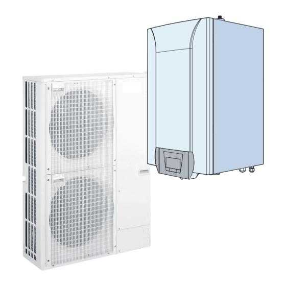
- Page 1 MW-3000529-01 Installation and Service Manual Reversible air/water "Split Inverter" heat pump Platinum BC iPlus iMPI/H 4-8 iMPI/E 4-8 iMPI/H 11-16 iMPI/E 11-16 iMPI/H 4–8 insulated iMPI/E 4-8 insulated iMPI/H 11–16 insulated iMPI/E 11-16 insulated...
-
Page 2: Table Of Contents
Contents Contents Safety instructions and recommendations ..............5 Safety . - Page 3 Contents 6.3.1 Connect and configure the iMPI heat pump with electrical back-up with a direct circuit, a circuit with mixing valve, a low-loss header and two TXM connected thermostats ......... . 41 Connection for the iMPI heat pump with hydraulic back-up with a direct circuit .
- Page 4 Contents 10.2.3 Installer \DHW menu ..............79 10.2.4 Installer \DHW\ADV menu .
-
Page 5: Safety Instructions And Recommendations
1 Safety instructions and recommendations Safety instructions and recommendations Safety Operation Danger This appliance can be used by children aged from 8 years and above and persons with reduced physical, sensory or mental capabilities or lack of experience and knowledge if they have been given supervision or instruction concerning use of the appliance in a safe way and understand the haz... -
Page 6: General Instructions
1 Safety instructions and recommendations Domestic wa Draining the appliance: 1. Shut off the domestic cold water inlet. 2. Open a hot water tap in the installation. 3. Open a valve on the safety unit. 4. When the water stops flowing, the appliance has been drained. The pressure limiter device (safety valve or safety unit) must be regularly oper... -
Page 7: Refrigerant Safety
1 Safety instructions and recommendations Refrigerant safety Warning Refrigerant fluid and pipes: Use only R410A refrigerant fluid to fill the installation. Use tools and pipe components especially designed for use with R410A refrigerant fluid. Use copper pipes deoxidised with phosphorus to carry the re frigerant fluid. -
Page 8: Hydraulic Safety
1 Safety instructions and recommendations In order to limit the risk of being scalded, a thermostatic mixing valve must be installed on the domestic hot water flow pipes. Hydraulic safety When making the hydraulic connection, it is imperative that the standards and corresponding local directives be respected. -
Page 9: Liabilities
1 Safety instructions and recommendations After maintenance or repair work, check the entire heating system to en sure that there are no leaks. Remove the casing only to perform maintenance and repair work. Put the casing back in place after maintenance and repair work. Liabilities Manufacturer's liability Our products are manufactured in compliance with the requirements of the various Directives appli... -
Page 10: About This Manual
2 About this manual About this manual Additional documentation This manual contains information on the heat pump's indoor module, in cluding the domestic hot water tank, as well as various items of informa tion on the outdoor unit. For additional information on the outdoor unit, refer to the manual provided with that unit. - Page 11 2 About this manual Fig.2 Symbols used on the data plate 1 Information concerning the heat pump: refrigerant type, maximum allowable operating pressure 2 The symbol indicates compatibility with the TXM connected ther mostat. 3 Information on the electrical back-up: power supply and maximum output (only for versions with electrical back-up) 4 Before installing and commissioning the appliance, carefully read the instruction manuals provided...
-
Page 12: Technical Specifications
3 Technical specifications Technical specifications Homologations 3.1.1 Directives This product complies with the requirements of the following European Di rectives and Standards: Pressure Equipment Directive 2014/68/EU Low Voltage Directive 2014/35/EU Generic standard: EN 60335-1 Relevant standards: EN 60335-2-21, EN 60335-2-40 Electromagnetic Compatibility Directive 2014/30/EU Generic standards: EN 61000-6-3, EN 61000-6-1 Relevant Standard: EN 55014... - Page 13 3 Technical specifications Tab.2 Conditions of use AWHP 11 MR-2 AWHP 16 MR-2 AWHP 11 TR-2 AWHP 16 TR-2 Limit water operating temperatures in heating mode +18 °C/+60 °C +18 °C/+60 °C Limit outdoor air operating temperatures in heating mode -20 °C/+35 °C -20 °C/+35 °C Limit water operating temperatures in cooling mode for uninsulated models...
-
Page 14: Heat Pump Weight
3 Technical specifications Tab.6 Common specifications Measure Unit AWHP 4.5 AWHP 6 AWHP 8 AWHP 11 AWHP 11 AWHP 16 AWHP 16 ment type MR-3 MR-2 MR-2 TR-2 MR-2 TR-2 Power volt age of the outdoor unit Start-up amperage Maximal 29.5 29.5 amperage... - Page 15 3 Technical specifications Product name AWHP-2 iMPI AWHP-2 iMPI AWHP 4.5 MR AWHP 6 MR-3 Water-to-water heat pump Brine-to-water heat pump Low-temperature heat pump Equipped with a supplementary heater Heat pump combination heater Prated Rated heat output under average conditions Prated Rated heat output under colder conditions Prated...
- Page 16 3 Technical specifications Product name AWHP-2 iMPI AWHP-2 iMPI AWHP 4.5 MR AWHP 6 MR-3 Supplementary heater Psup Rated heat output Type of energy input Electricity Electricity Other specifications Capacity control Variable Variable Sound power level, indoors - outdoors 49 – 61 49 –...
- Page 17 3 Technical specifications Product name AWHP-2 iMPI AWHP-2 iMPI AWHP-2 iMPI AWHP 8 MR-2 AWHP 11 AWHP 16 MR-2 MR-2 AWHP 11 AWHP 16 TR-2 TR-2 ƞ Seasonal space heating energy efficiency under average conditions ƞ Seasonal space heating energy efficiency under colder conditions ƞ...
-
Page 18: Sensor Specifications
3 Technical specifications 3.2.4 Sensor specifications Outside sensor specifications Tab.11 Outside sensor Temperature °C Resistance 2392 2088 1811 1562 1342 1149 Flow sensor specifications Tab.12 Flow sensor Temperature in °C Resistance in Ω 32014 19691 12474 10000 8080 5372 3661 2535 1794 1290... -
Page 19: Dimensions And Connections
3 Technical specifications Dimensions and connections 3.3.1 AWHP 4.5 MR Fig.4 (417.5) 417.5 10 X 21 MW-1000430-1 1 1/4" refrigerant fluid connection 2 1/2" refrigerant gas connection 3.3.2 AWHP 6 MR-3 Fig.5 404.5 23.2 22.3 193.5 154.5 MW-1000919-1 1 1/4" refrigerant fluid connection 2 1/2"... -
Page 20: Awhp 8 Mr-2
3 Technical specifications 3.3.3 AWHP 8 MR-2 Fig.6 MW-M001442-2 1 3/8" refrigerant fluid connection 2 5/8" refrigerant gas connection AWHP-2 iMPI 7685645 - v04 - 07032018... -
Page 21: Awhp 11 Mr-2 - Awhp 16 Mr-2 - Awhp 11 Tr-2 - Awhp 16 Tr-2
3 Technical specifications 3.3.4 AWHP 11 MR-2 – AWHP 16 MR-2 – AWHP 11 TR-2 – AWHP 16 TR-2 Fig.7 1350 MW-M001443-2 1 3/8" refrigerant fluid connection 2 5/8" refrigerant gas connection 7685645 - v04 - 07032018 AWHP-2 iMPI... -
Page 22: Impi With Hydraulic Back-Up
3 Technical specifications 3.3.5 iMPI with hydraulic back-up Fig.8 iMPI/H 56,5 65 55 55 MW-3000532-01 1 Heating circuit flow G 1" 4 Back-up boiler return G 1" 2 Heating circuit return G 1" 5 5/8" refrigerant gas connection 3 Back-up boiler flow G 1" 6 3/8"... -
Page 23: Impi With Electrical Back-Up
3 Technical specifications 3.3.6 iMPI with electrical back-up Fig.10 iMPI/EM, iMPI/ET 56,5 MW-3000530-01 1 Heating circuit flow G 1" 3 5/8" refrigerant gas connection 2 Heating circuit return G 1" 4 3/8" refrigerant fluid connection Fig.11 iMPI/EMI, iMPI/ETI MW-3000531-01 1 Heating circuit flow G 1" 3 5/8"... -
Page 24: Electrical Diagram
3 Technical specifications Electrical diagram Fig.12 7685744 7679483 FUSE HPC-01 Sensor Liquid 7622566 7679484 Sensor Target 7681340 7691321 7679481 Water FUSE Sensors SCB-04B 7679489 Pump 7621758 Safety T°C 3 Way 7622059 Thermostat Flow Valve EHC-04 X17 X16 7679482 Pump Room Unit X5 X19 FUSE 7619601... - Page 25 3 Technical specifications Tab.14 Wiring diagram legend 230 V ~ Power supply 3 WAY VALVE Three-way valve 3-WAY DHW VALVE 3-way domestic hot water valve BL1 MULTIFUNCTION BL1 multifunction BL2 MULTIFUNCTION BL2 multifunction CONDENSATE SENSOR ON/OFF Underfloor heating DOMESTIC HOT WATER T° HIGH Temperature at the top of the tank DOMESTIC HOT WATER T°...
-
Page 26: Description Of The Product
4 Description of the product Description of the product Operating principle The outdoor unit produces heat or cold and transfers it to the indoor mod ule via the refrigerant in the plate exchanger. The indoor module is equip ped with a specific control system which is used to adjust the temperature of the heating water to the needs of the home. -
Page 27: Standard Delivery
4 Description of the product Standard delivery Delivery includes several packages: One indoor module package One outdoor unit package Contents of the indoor module package: An indoor module An outside sensor An installation and service manual A user guide 7685645 - v04 - 07032018 AWHP-2 iMPI... -
Page 28: Before Installation
< 1 °f 7 - 15 Total water hardness °dH 4 - 8.5 mmol/l 0.7 - 1.5 Important If water treatment proves necessary, Baxi recommends the follow ing manufacturers: Cillit Climalife Fernox Permo Sentinel AWHP-2 iMPI 7685645 - v04 - 07032018... -
Page 29: Special Precautions For The Connection Of The Heating Circuit
5 Before installation 5.2.2 Special precautions for the connection of the heating cir cuit When making the connection, it is imperative that the standards and corre sponding local directives be respected. Caution The hydraulic installation must be capable of handling a minimum flow rate at all times: If radiators are connected directly to the heating circuit: install a differential valve between the indoor module and the heating cir... -
Page 30: Overall Space Needed By The Indoor Module
5 Before installation Data plate on the indoor module Fig.16 MW-3000537-01 Data plate on the outdoor unit Fig.17 MW-M001832-1 5.3.2 Overall space needed by the indoor module Fig.18 Allow sufficient space around the heat pump's indoor module to ensure adequate access and facilitate maintenance. 1200 MW-3000536-01 AWHP-2 iMPI... -
Page 31: Distance Between Modules
5 Before installation 5.3.3 Distance between modules Fig.19 Diagram of distances between mod 1 Outdoor unit ules 2 Indoor module Allow a refrigeration connection of at least 2 m by making one or two horizontal loops in order to lessen these disruptions. If the refrigeration connection between the outdoor unit and the indoor module is less than 2 m, the following disruptions may occur: Functional disruptions caused by a fluid overload... - Page 32 5 Before installation Caution If the outside temperatures become negative, take the necessa ry precautions to prevent the risk of freezing in the evacuation pipes. Prevent any risk of the condensates freezing in a passing-by zone. Fig.21 Installation of a single outdoor unit or several outdoor units MW-6000252-2 1.
- Page 33 5 Before installation Fig.23 Distances of the appliance from the wall 1000 Tab.17 Minimum dimensions in mm AWHP 4.5 MR AWHP 11 MR-2 AWHP 6 MR-3 AWHP 16 MR-2 AWHP 8 MR-2 AWHP 11 TR-2 AWHP 16 TR-2 1000 1000 1500 Position of the outdoor unit Carefully choose the position of the outdoor unit in relation to neighbours...
-
Page 34: Fitting The Outdoor Sensor
5 Before installation Important The condensates discharge must be regularly cleaned in order to prevent any blockages. Fitting the outdoor sensor 1. Choose the optimum location for the outdoor sensor. Fig.25 Mounting the outdoor sensor 2. Put the 2 plugs in place, delivered with the sensor (diameter 4 mm). 3. - Page 35 5 Before installation Fig.27 MW-3000014-2 7685645 - v04 - 07032018 AWHP-2 iMPI...
-
Page 36: Connecting Diagrams
6 Connecting diagrams Connecting diagrams Connection for the iMPI heat pump with electrical back-up with a domestic hot water tank and an underfloor heating circuit Fig.28 iMPI with a domestic hot water tank, an underfloor heating circuit, a TXM connected thermostat and an electrical back-up 230V ou 400V 50Hz... -
Page 37: Connect And Configure The Impi Heat Pump With Electrical Back-Up With A Domestic Hot Water Tank And A
6 Connecting diagrams 6.1.1 Connect and configure the iMPI heat pump with electrical back-up with a domestic hot water tank and a direct cir cuit Fig.29 230V ou 400V 50Hz EHC-04 MW-5000766-2 1 Outdoor temperature sensor 4 Heating/domestic hot water reversal valve 2 Wiring kit for direct underfloor heating 5 Domestic hot water sensor 3 TXM connected thermostat... -
Page 38: Direct Circuit
6 Connecting diagrams Connection for the iMPI heat pump with electrical back-up with 2 circuits and a buffer tank Fig.30 iMPI with a direct circuit, a circuit with mixing valve, two TXM connected thermostats and an electrical back-up Ö & Ö... -
Page 39: Connect And Configure The Impi Heat Pump With Electrical Back-Up With 2 Circuits And A Buffer Tank
6 Connecting diagrams 6.2.1 Connect and configure the iMPI heat pump with electrical back-up with 2 circuits and a buffer tank Fig.31 SCB-04B Ö & Ö & Ö & Ö & EHC-04 230V 50Hz MW-5000768-3 1 Outdoor temperature sensor 8 Outdoor unit bus connection 2 Safety thermostat for underfloor heating flow 9 230 V power supply connection between the EHC–... -
Page 40: Connection For The Impi Heat Pump With Electrical Back-Up With 2 Circuits With A Low-Loss Header
6 Connecting diagrams Connection for the iMPI heat pump with electrical back-up with 2 circuits with a low-loss header Fig.32 iMPI with a direct circuit, a circuit with mixing valve, two TXM connected thermostats and an electrical back-up 230V 50Hz MW-5000760-2 1 Outdoor unit 6 Thermostat connected to circuit A... -
Page 41: Connect And Configure The Impi Heat Pump With Electrical Back-Up With A Direct Circuit, A Circuit With Mixing
6 Connecting diagrams 6.3.1 Connect and configure the iMPI heat pump with electrical back-up with a direct circuit, a circuit with mixing valve, a low-loss header and two TXM connected thermostats Fig.33 SCB-04B EHC-04 230V 50Hz MW-5000769-2 1 Outdoor temperature sensor 8 Outdoor unit bus connection 2 Safety thermostat for underfloor heating flow 9 230 V power supply connection between the EHC–... -
Page 42: Connection For The Impi Heat Pump With Hydraulic Back-Up With A Direct Circuit
6 Connecting diagrams Connection for the iMPI heat pump with hydraulic back-up with a direct circuit Fig.34 iMPI with a direct circuit, a TXM connected thermostat and a hydraulic back-up 230V 230V 50Hz 50Hz MW-5000758-2 1 Outdoor unit 4 Direct underfloor heating connection kit 2 Connected thermostat 5 Floor-standing gas/oil-fired boiler 3 Indoor module... - Page 43 6 Connecting diagrams 1. Connect the accessories and options to the EHC–04 PCB, respect ing the 230-400 V and 0-40 V cable feed-throughs. 2. On initial start-up, or after a reset of the factory parameters, set the CN1 and CN2 parameters according to the output of the outdoor unit.
-
Page 44: Installation
7 Installation Installation General Caution Installation of the heat pump must be done by a qualified profes sional in accordance with prevailing local and national regulations. Preparation 7.2.1 Mounting the indoor module Fitting the mounting rail Fig.36 Drilling and mounting the rail 1. -
Page 45: Hydraulic Connections
7 Installation Hydraulic connections 7.3.1 Connecting the heating circuit Heating installations must be able to guarantee a minimum flow rate at all times. This is defined by the parameter HP010. The nominal flow rate sought by the heat pump for optimum running is defined by the parameter HP069. -
Page 46: Connecting The Safety Valve Drain Pipe
7 Installation 7.3.2 Connecting the safety valve drain pipe Fig.38 Removing the front panel 1. Remove the front panel by pulling firmly upwards. MW-3000539-01 Fig.39 Orifice 2. Pass the outlet pipe from the safety valve through the opening provi ded for this purpose. 3. -
Page 47: Connecting The Refrigeration Link
7 Installation Length of refrig 10 m 15 m 20 m 30 m Yg/m eration pipe (1) The outdoor module is pre-charged with 1,300 kg of refrigerant fluid. (2) Calculation: Xg = Yg/m x (pipe length (m) – 7) Tab.19 Length of refrigeration pipe AWHP 6 MR-3 AWHP 8 MR-2... - Page 48 7 Installation Fig.42 Release noise 2. Push a screwdriver gently into the 5/8" nut. A release noise should be heard, which is proof that the exchanger is watertight. Pfffff... MW-3000543-01 Fig.43 Unscrewing the 3/8" and 5/8" nuts. 3. Unscrew the 3/8" and 5/8" nuts. MW-3000598-01 Fig.44 Discarding the nuts or caps...
- Page 49 7 Installation Fig.47 Connecting the pipes 8. Connect the pipes and tighten the nuts with a dynamometric span ner. Notice Apply refrigerant oil to the beaded parts to facilitate tightening and improve the seal. Option Model Only for models AWHP 4.5 MR For other models Tab.20 Torque load...
-
Page 50: Test The Tightness
7 Installation 13. Connect the pipes and tighten the nuts with a dynamometric span ner. Notice Apply refrigerant oil to the beaded parts to facilitate tightening and improve the seal. Fig.50 Connecting the pipes A Do not use a spanner on this part of the valve, danger of the refrig erant leaking B Recommended position of the spanners for tightening the nut Tab.21... -
Page 51: Evacuation
7 Installation 7.4.4 Evacuation Fig.52 Stop valves 1. Check that isolation valves A and B / C are closed. 2. Connect the vacuum gauge and the vacuum pump to the service connection on isolation valve A. 3. Produce a vacuum in the indoor module and the refrigeration con nection pipes. -
Page 52: Routing The Cables
7 Installation Make the electrical connections on the appliance in accordance with the information given in the electrical schematics delivered with the appli ance, Make the electrical connections on the appliance in accordance with the recommendations of these instructions. Important Earthing must comply with the prevailing installation standards. -
Page 53: Description Of The Connection Terminal Blocks
7 Installation Caution Separate the sensor cables from the 230/400 V circuit cables. 7.5.3 Description of the connection terminal blocks EHC–04 PCB terminal block Fig.55 Indoor module terminal block X1 230 V - 50 Hz power supply Hydraulic version: Hydraulic back-up pump Electrical version: Electrical back-up - stage 1 Hydraulic version: Hydraulic back-up ON/OFF contact Electrical version: Electrical back-up - stage 2... -
Page 54: Accessing The Pcbs And Connection Terminal Block
7 Installation Tab.24 Outdoor unit Unit AWHP AWHP 6 AWHP 8 AWHP 11 AWHP 11 AWHP 16 AWHP 16 4.5 MR MR-3 MR-2 MR-2 TR-2 MR-2 TR-2 Power supply type Single Single Single Single Three Single Three phase phase phase phase phase phase... - Page 55 7 Installation Fig.58 3. Pivot the PCB support for routing the cables and connecting certain options. MW-3000597-01 Connecting the cables to the PCBs Use original connectors inserted into the various terminal blocks. The connectors are keyed. If there are no connectors on the terminal block to be used, use the con nector provided with the kit.
-
Page 56: Electrically Connecting The Outdoor Unit
7 Installation 7.5.6 Electrically connecting the outdoor unit Fig.60 L1 L2 L3 S1 S2 S3 MW-2000376-3 A Single-phase power supply for AWHP 4.5 MR 1 Power supply B Single-phase power supply for AWHP 6 MR-3, 2 Communication bus AWHP 8 MR-2, AWHP 11 MR-2 , AWHP 16 MR-2 C Three-phase power supply for AWHP 11 TR-2, AWHP 16 TR-2 AWHP-2 iMPI... - Page 57 7 Installation Fig.61 1. Remove the service panel. Service panel for AWHP 4.5 MR Service panel for AWHP 6 MR-3, AWHP 8 MR-2, AWHP 11 MR-2 , AWHP 16 MR-2 Service panel for AWHP 11 TR-2, AWHP 16 TR-2 MW-1000787-3 2.
-
Page 58: Connecting The Outdoor Unit Bus
7 Installation 7.5.7 Connecting the outdoor unit bus Fig.62 1. Connect the outdoor unit bus to the X23 connector in the indoor module's EHC–04 central unit PCB. 2. Position the SW8–3 switch (except with the AWHP 4.5 MR) for the outdoor unit PCB to ON. -
Page 59: Connecting The Power Supply For The Electrical Back-Up
7 Installation 7.5.10 Connecting the power supply for the electrical back-up 1. Choose the total output of the electrical back-up according to the size of the home and its energy performance. There are 2 output stages, as shown in the following table: Tab.27 Electrical back-up power supply Back-up power supply... - Page 60 7 Installation Fig.65 Three-phase power supply 4. Three-phase power supply: Insert the bridge according to the output of the electrical back-up, taking care to push it to the bottom of the connector. Connect the electrical back-up power supply (press the button to be able to insert the wire into the connector correctly and secure L1 L2 L3 D3 N L1 L2 L3 D3 N...
- Page 61 7 Installation Connecting a boiler fitted with a control panel with no input Fig.66 Boiler fitted with a control panel with no input TAM MW-C003337-1 1 Domestic hot water load pump power supply CS Safety contact 1. Connect the electrical cables as per the connection diagram. 2.
-
Page 62: Connecting A Swimming Pool
7 Installation Connecting a boiler fitted with a control panel with an input Fig.67 Boiler fitted with a control panel with an input TAM 2 x 0,75 mm2 MW-C003336-1 1 Domestic hot water load pump power supply TAM Room thermostat 7.5.11 Connecting a swimming pool The swimming pool is not heated when the contact is open (factory set... -
Page 63: Connecting The Options
7 Installation Connecting the options Fig.69 1. Connect the options according to the configuration of the installation to the X12 or X19 connector on the EHC–04 PCB in the indoor mod ule. Tab.30 Connecting the options to X12 X12 connector Description R-Bus terminals Connection of the TXM connected thermostat,... -
Page 64: Filling The Installation
7 Installation Value of the CP640 Value of the AP098 The BL1 blocking Operating mode for If the OT contact is If the OT contact is parameter parameter input is the heat pump open closed 1 (Default value) 1 (Default value) Closed Heating No heating demand Heating demand... -
Page 65: Commissioning
8 Commissioning Commissioning General The heat pump is commissioned: When it is used for the first time; After a prolonged shut-down; After any event that may require complete reinstallation. Commissioning of the heat pump allows the user to review the various set tings and checks to be made to start up the heat pump in complete safety. -
Page 66: Cnf Menu
8 Commissioning 2. Arm the indoor module and outdoor unit circuit breakers on the elec tric panel by setting them to the I position. The heat pump is switched on. When powering up for the first time, the control panel displays the CNF menu which enables the type of outdoor unit present in the installation to be set. -
Page 67: Using The Installation Wizard On The Control Panel
8 Commissioning Fig.72 3. LOAD to recover information from the various control boards Fig.73 4. Software version of the central unit PCB Fig.74 5. Parameter version of the central unit PCB Fig.75 6. The venting cycle is run automatically on start-up of the appliance, if an error occurs or during manual reset. -
Page 68: Checking The Minimum Flow
8 Commissioning Fig.77 Fig.78 3. Select the number corresponding to the installation type by pressing key. Selecting the installation type enables automatic configuration of the parameters required for the control panel to op 19° erate correctly (gradient, maximum circuit temperature, etc.). For a configuration which differs from those proposed here, press the key on the control panel and configure the parameters manually. - Page 69 8 Commissioning 6. After about 10 minutes, vent the air in the heating system. 7. Check the hydraulic pressure. If necessary, top up the water level in the heating system. 8. Check for clogging on the filter on the heating return and the domes tic hot water return.
-
Page 70: Operation
9 Operation Operation Use of the control panel 9.1.1 Control panel description Description of the keys Fig.79 : back to the previous level without saving the modifications made : manual reset : accessing the heating parameters : lowering the value : accessing the domestic hot water parameters : raising the value : MODE display... - Page 71 9 Operation Hydraulic pressure in the system The display alternates between the hydraulic pressure for the system and the measured flow temperature. Fig.84 Steady symbol: displayed when indicating the system's hydraulic pressure value Flashing symbol: pressure in the system too low XXX Pressure value in the system (in bar) or flow temperature (in °C) Cooling mode Fig.85...
-
Page 72: Browsing In The Menus
9 Operation COUNTERS / TIME PROG / Sub-Menus CLOCK Fig.90 COUNTERS sub-menu (CNT) TIME PROG sub-menu: Timer programming dedicated to heat ing and domestic hot water production (CIRC A, CIRC B, ECS) Timer program for Monday Timer program for Tuesday Timer program for Wednesday Timer program for Thursday Timer program for Friday... -
Page 73: Description Of The Pcbs
9 Operation Important The different menus are only accessible when the icons flash. Fig.94 Press the key to: access the next menu, access the next sub-menu, access the next parameter, MW-1000576-1 increase the value. Fig.95 Press the key to: access the previous menu, access the previous sub-menu, access the previous parameter MW-2000370-1... -
Page 74: Shutting Down The Cooling Function
9 Operation Fig.99 1. Go to stop mode by pressing the key. MW-5000027-4 Fig.100 2. Select the heating mode by pressing the key. 3. Confirm by pressing the key. MW-5000133-3 Fig.101 4. Select the heating shut-down pressing the key. The screen displays: The frost protection function continues to run. - Page 75 9 Operation The radiator valves in rooms where there is a risk of frost must be fully open. 7685645 - v04 - 07032018 AWHP-2 iMPI...
-
Page 76: 10 Settings
10 Settings 10 Settings 10.1 Modifying the installer parameters Caution Altering the factory settings may impair operation of the appliance. The parameters in the Installer menu may only be changed by a qualified professional. Fig.102 1. Go to the Installer menu. -
Page 77: Installer \Circa And Circb Menu
10 Settings 10.2.1 Installer \CIRCA and CIRCB menu CP : Circuits Parameters = Heating circuit parameters Tab.39 Parameter Description Factory setting Factory setting CIRCA CIRCB CP000 Maximum Flow Temperature setpoint zone Electrical back-up: For circuit A: Can be set from 7 °C to 100 °C Hydraulic back-up: CP020 Type of circuit A, connected to the EHC–04 PCB:... -
Page 78: Installer \Circa And Circb\Adv Menu
10 Settings Parameter Description Factory setting Factory setting CIRCA CIRCB CP340 Type of Reduced Night Mode, stop or maintain heating of circuit Stop heat demand 1 = Continue heat demand CP470 Setting of the screed drying program of the zone 0 = deactivated Can be set from 1 to 30 days CP480... -
Page 79: Installer \Dhw Menu
10 Settings Description of the ADV advanced parameters Factory setting CIRCB CP530 Pulse Width Modulation pump speed per zone Can be set from 0 % to 100 % Do not modify this setting CP730 Selection of heat up speed of the zone 0 =Extra Slow 1 =Slowest 2 =Slower... -
Page 80: Installer \Ehc-04 And Scb-04 Menu
10 Settings Tab.42 List of ADV parameters in the sub-menu of the Installer menu Description of the ADV advanced parameters Factory setting DP004 Legionella mode protection calorifier 0 =Disabled 1 = on: the domestic hot water tank is superheated to 65 °C for 20 minutes once a week. - Page 81 10 Settings Parameter Description Factory setting Factory setting EHC–04 SCB-04 AP063 Maximum flow temperature setpoint for burning at central heating Hydraulic back- not available Can be set from 20 °C to 90 °C up: 90 Electrical back- up: 75 AP075 Outdoor temperature neutral band between heating and cooling.
-
Page 82: Installer \Ehc-04 And Scb-04\Adv Menu
10 Settings Parameter Description Factory setting EHC–04 HP061 Hybrid mode management: 0 =No Hybrid 1 =Hybrid Cost 2 =Primary Energy 3 =Hybrid CO2 HP065 Electrical CO2 emission in heating mode Can be set from 0 to 100 (x0.01) Value accepted when HP061=3 HP066 Electrical CO2 emission in DHW mode Can be set from 0 to 100 (x0.01) - Page 83 10 Settings Description of the ADV advanced parameters Factory setting Factory setting EHC–04 SCB-04 AP072 Type of the humidity sensor used 0 =No 1 =OnOff 2 =0-10V sensor AP101 Disable (0) or Enable (1) the de-aeration cycle not available 0 =Off 1 =Auto 2 =On AP102...
- Page 84 10 Settings ADV parameter Description of the ADV advanced parameters Factory setting EHC–04 HP047 Maximum time at maximum outside temperature to start back up in CH mode when dynamic timer selected Can be set from 1 to 10 minutes Value accepted when HP031 = 0 HP048 Maximum time at maximum outside temperature to start back up in CH mode when dynamic timer selected...
-
Page 85: Counters /Time Prog / Clock Menus
10 Settings ADV parameter Description of the ADV advanced parameters Factory setting EHC–04 PP016 Maximum central heating pump speed (%) 100% Maximum pump speed in heating mode Can be set from 20 to 100% PP018 Minimum central heating pump speed (%) Minimum pump speed in heating mode Can be set from 20 to 100% Auto detect... -
Page 86: Counters, Time Prog, Clock
10 Settings Parameter Description Unit EHC-04 SCB04-B AC027 Counter that shows the number of pump starts AC028 Total working time of the first stage of backup hours AC029 Total working time of the second stage of backup hours AC030 Total startings of the first stage of backup AC031 Total startings of the second stage of backup DC002... -
Page 87: Counters, Time Prog, Clock \Clk Menus
10 Settings 10.3.3 COUNTERS, TIME PROG, CLOCK \CLK menus Tab.51 CLK parameter Unit HOURS Can be set from 0 to 23 available MINUTE Can be set from 0 to 59 available DATE Can be set from 1 to 31 available MONTH Can be set from 1 to 12 available... -
Page 88: Setting The Switch Between Heating And Production Of Domestic Hot Water
10 Settings Back-up operation if defrosting the outdoor unit When the outdoor unit is undergoing defrosting, the control unit ensures full protection of the system by starting up the back-ups if necessary. Additional protection is provided if the water temperature falls too sharply. In this case, the outdoor unit is shut down. -
Page 89: Running The Back-Up In Domestic Hot Water Mode
10 Settings Live Operating description Heating only. When the DP120 differential is reached, domestic hot water production is triggered. If there is not enough domestic hot water (e.g. if the domestic hot water does not heat up quickly enough): reduce the trip differential (hysteresis) by modifying the value of the DP120 parameter. The DHW tank will then heat up the water more quickly. -
Page 90: Selecting The Type Of Outdoor Unit And The Type Of Back-Up (Cn1 Et Cn2)
10 Settings Fig.107 3. Select the AP103 parameter corresponding to language selection by pressing the keys. 4. Confirm by pressing the key. Fig.108 5. Access the languages available by pressing the key. Fig.109 6. Select the language by pressing the keys until the desired language is displayed. -
Page 91: Setting The Heating Curve
10 Settings Output of the outdoor unit 6 kW 8 kW 11 kW 16 kW Tab.56 Value of the CN1 and CN2 parameters with an electrical back- Output of the outdoor unit 4.5 kW 6 kW 8 kW 11 kW 16 kW 10.5.3 Setting the heating curve... -
Page 92: Configuring A Hydraulic Back-Up
10 Settings Energy meter specifications Minimum admissible voltage: 27 V Minimum admissible intensity: 20 mA Minimum pulse time: 25 ms Maximum frequency: 20 Hz Pulse weighting: between 1 and 1000 Wh Choose meters whose impulse number per kW is a multiple of 1000. Energy metering provides information on: electrical energy consumption, the production of thermal energy for heating, domestic hot water and... -
Page 93: Configuring The Hybrid Operating Mode Of A Hydraulic Back-Up
10 Settings Boiler installation manual. Configuring a boiler not equipped with a room thermostat input 1. Set the following installer parameters on the boiler control panel: Switch the boiler control system to 24h/24 comfort mode. Heating set point temperature = Domestic hot water set point tem perature + 5°C. -
Page 94: Configuring A Convection Fan Or Underfloor Cooling
10 Settings Fig.113 Influence of outdoor temperatures C COP: Coefficient of performance and bi-valency. Threshold coefficient of performance T Outdoor temperature HP051 parameter: Minimum outside temperature below which Heat Pump is stopped HP000 parameter: Outside bivalence temperature MW-5000542-1 10.5.7 Configuring a convection fan or underfloor cooling This function is only available when the type of circuit selected is under... -
Page 95: Screed Drying With The Aid Of The Heat Pump
10 Settings For more information, see Description of the PCBs, page 73 CNF menu, page 66 10.5.8 Screed drying with the aid of the heat pump The screed drying program reduces the drying time of a freshly poured screed floor. The settings for these temperatures must follow the screed layer's rec... -
Page 96: Drying Screed Without The Heat Pump Outdoor Unit
10 Settings 10.5.9 Drying screed without the heat pump outdoor unit. Fig.118 The indoor module can be used for drying screed using the electrical back-up in forced operation mode. It is not necessary to connect the out door unit. 1. Switch on the heat pump and activate the screed drying function. 2. -
Page 97: 10.5.12 Reducing The Noise Level Of The Outdoor Unit
10 Settings 3. Choose the contact directions of the BL1 IN and BL2 IN multifunc tion inputs by setting the AP098 and AP099 parameters. Tab.66 Parameter Description AP098 Blocking input 1 contact direction configuration 0 = input active on Open contact 1 = input active on Closed contact AP099 Blocking input 2 contact direction configuration... -
Page 98: Reading Out Measured Values
10 Settings Fig.119 6. Select the auto detection parameter by pressing the keys. 7. Confirm auto detection by pressing the key. The automatic detection function is running. 10.6 Reading out measured values The measured values are available in the Information menu of the dif... - Page 99 10 Settings Parameter Description Unit EHC-04 SCB04-B CM040 Measure Zone Flow Temperature or DHW °C temperature CM060 Current Pump speed of zone CM120 Zone Current Mode: 0 =Scheduling =Manual 2 =Antifrost 3 =Temporary CM130 Current activity of the zone: 0 =Anti frost 1 =Reduced 2 =Comfort 3 =Anti legionella...
-
Page 100: Control System Sequence
10 Settings Parameter Description EHC--04 SCB04-B P00.01 HMI parameter version 10.6.1 Control system sequence Tab.72 List of statuses and sub-statuses Status Appliance: AM012 parameter Appliance sub status: AM014 parameter 00= total system shut-down 1= heating / cooling / domestic hot water de Heat Demand mand 00 = off... - Page 101 10 Settings Status Appliance: AM012 parameter Appliance sub status: AM014 parameter 4= operating in domestic hot water mode 30= normal operation The compressor or the back-ups are running. 31= internal set point limited If the heating set point on the heat pump differs from the system set point. 60= pump post-operation Heat pump and back-up shut-down, system pump operation.
- Page 102 10 Settings Status Appliance: AM012 parameter Appliance sub status: AM014 parameter Blocking Mode 30= normal operation. The compressor or the back-ups are running. 31= internal set point limited If the heating set point on the heat pump differs from the system set point. 60= pump post-operation Heat pump and back-up shut-down, system pump running.
- Page 103 10 Settings Status Appliance: AM012 parameter Appliance sub status: AM014 parameter Frost protection 30= normal operation The compressor or the back-ups are running. 31= internal set point limited If the heating set point on the heat pump differs from the system set point. 60= pump post-operation Heat pump and back-up shut-down, system pump post-operation.
-
Page 104: 11 Maintenance
11 Maintenance 11 Maintenance 11.1 General Maintenance operations are important for the following reasons: To guarantee optimum performance. To extend the life of the equipment. To provide an installation which offers the user optimum comfort over time. Caution Only qualified professionals are authorised to carry out mainte nance work on the heat pump and the heating system. -
Page 105: Checking The Safety Devices
11 Maintenance 11.3.1 Checking the safety devices 1. Check that the safety devices are operating correctly, particularly the safety valve on the heating circuit. 2. Check the tightness of the refrigerant circuit using a sniffer. 3. Check the electrical connections. 4. -
Page 106: Replacing The Battery In The Control Panel
11 Maintenance Fig.123 Removing the retaining ring and the 3. Remove the spring retaining ring. filter 4. Remove the filter. 5. Inspect and clean the filter. Replace it if necessary. 6. Remount the filter. 7. Tighten the connection. 8. Open the valve on the exchanger. MW-L000333-1 11.4.2 Replacing the battery in the control panel... -
Page 107: 12 Troubleshooting
12 Troubleshooting 12 Troubleshooting 12.1 Resetting the safety thermostat Danger Before carrying out any work, cut off the mains supply to the in door module and the electrical back-up immersion heaters. If the safety thermostat is tripped: 1. Cut off the mains supply to the indoor module and the electrical back-up immersion heaters. - Page 108 12 Troubleshooting Error Message Description code H00.32 TOutside Open Outside temperature sensor is either removed or measures a temperature below range Check the wiring between the central unit PCB and the sensor. Check that the sensor has been fitted properly. Check the Ohmic value of the sensor.
- Page 109 12 Troubleshooting Error Message Description code H02.04 Parameter Error Parameter Error Restore the factory settings. If the error is still present: change the central unit PCB. H02.05 CSU CU mismatch CSU does not match CU type Software change (software number or version parameter inconsistent with the mem ory).
-
Page 110: Fault Codes
12 Troubleshooting Error Message Description code H06.01 HP Unit Failure Heat Pump Unit Failure occured Heat pump outdoor unit fault Check the wiring between the central unit PCB and the communication bus on the outdoor unit. Check the connection of the communication cable between the central unit PCB and the interface PCB. -
Page 111: Alarm Codes
12 Troubleshooting Fault Message Description code E02.24 System flow locking active System water flow locking active No circulation: Check that the circulation pump is working. Check that the valves and thermostatic valves are open. Check the wiring. Check the pump supply: if the pump does not work, replace it. - Page 112 12 Troubleshooting Fig.130 2. Select the Malfunction menu by pressing the key. Fig.131 3. Select the PCB by pressing the key. The icon appears. Confirm the PCB selection by pressing the key: the PCB name appears. Important The Er:xxx parameter flashes. 000 corresponds to the number of stored errors.
-
Page 113: 13 Decommissioning And Disposal
13 Decommissioning and disposal 13 Decommissioning and disposal 13.1 Decommissioning procedure To decommission the heat pump temporarily or permanently: 1. Switch off the heat pump. 2. Shut off the electrical power supply to the heat pump: outdoor unit and indoor module. 3. - Page 114 13 Decommissioning and disposal AWHP-2 iMPI 7685645 - v04 - 07032018...
- Page 115 © Copyright All technical and technological information contained in these technical instructions, as well as any drawings and technical de scriptions supplied, remain our property and shall not be multiplied without our prior consent in writing. Subject to alterations.
- Page 116 7685645 - v04 - 07032018 7685645-001-04...
Need help?
Do you have a question about the Platinum BC iPlus and is the answer not in the manual?
Questions and answers