
Related Manuals for Baxi AWHP 22 TR–2


Summary of Contents for Baxi AWHP 22 TR–2
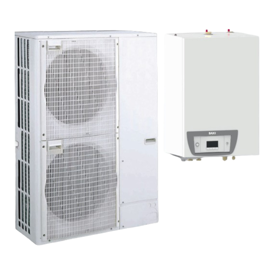
- Page 1 User Guide Reversible air/water "Split Inverter" heat pump Platinum BC iMax iHPI/E 22-27...
-
Page 2: Table Of Contents
Contents Contents Safety instructions and recommendations ..............4 Safety . - Page 3 Contents 6.5.1 List of measured values ............. . .29 6.5.2 Control system sequence .
-
Page 4: Safety Instructions And Recommendations
1 Safety instructions and recommendations Safety instructions and recommendations Safety Operation Danger This appliance can be used by children aged from 8 years and above and persons with reduced physical, sensory or mental capabilities or lack of experience and knowledge if they have been given supervision or instruction concerning use of the appliance in a safe way and understand the hazards involved. -
Page 5: Electrical Safety
1 Safety instructions and recommendations Electrical safety Before making any electrical connections, earth the appliance in accordance with prevailing standards. Danger Danger of electric shock: the length of the conductors between the traction arrester device and the terminal blocks must be such that the active conductors are put under tension before the earth conductor. -
Page 6: Hydraulic Safety
1 Safety instructions and recommendations Heating water and domestic water must not come into contact with each other. Domestic water must not circulate through the exchanger. Limit temperature at the draw-off point: the maximum domestic hot water temperature at the draw-off point is subject to special regulations in the various countries in which the appliance is sold in order to protect the user. -
Page 7: Liabilities
1 Safety instructions and recommendations Before working on the refrigeration circuit, switch off the appliance and wait a few minutes. Certain items of equipment such as the compressor and the pipes can reach temperatures in excess of 100 °C and high pressures, which may cause serious injuries. -
Page 8: Symbols Used
2 Symbols used Symbols used Symbols used in the manual This manual uses various danger levels to draw attention to special instructions. We do this to improve user safety, to prevent problems and to guarantee correct operation of the appliance. Danger Risk of dangerous situations that may result in serious personal injury. -
Page 9: Technical Specifications
3 Technical specifications Technical specifications Homologations 3.1.1 Directives This product complies with the requirements of the following European Directives and Standards: Pressure Equipment Directive 2014/68/EU Low Voltage Directive 2014/35/EU Generic standard: EN 60335-1 Relevant standard: EN 60335-2-40 Electromagnetic Compatibility Directive 2014/30/EU Generic standards: EN 61000-6-3, EN 61000-6-1 Relevant Standard: EN 55014 This product conforms to the requirements of European Directive... -
Page 10: Heat Pump Weight
3 Technical specifications Tab.3 Heating mode: outside air temperature +2 °C, water temperature at the outlet +35 °C. Performances in accordance with EN 14511-2. Measurement type Unit AWHP 22 TR–2 AWHP 27 TR-2 Heat output 16.11 14.70 Coefficient of Performance (COP) 3.13 3.13 Absorbed electrical power... -
Page 11: Combination Heaters With Medium-Temperature Heat Pump
3 Technical specifications 3.2.3 Combination heaters with medium-temperature heat pump Tab.8 Technical parameters for heat pump combination heaters (parameters declared for medium-temperature application) Product name iHPI iHPI AWHP 22 TR–2 AWHP 27 TR-2 Air-to-water heat pump Water-to-water heat pump Brine-to-water heat pump Low-temperature heat pump Equipped with a supplementary heater Heat pump combination heater... -
Page 12: Circulating Pump
3 Technical specifications Product name iHPI iHPI AWHP 22 TR–2 AWHP 27 TR-2 Annual energy consumption under warmer conditions 10025 11541 Rated air flow rate, outdoors for air-to-water heat pumps — 6000 6000 Prated is equal to the design load for heating Pdesignh , and the rated heat output of a supplementary heater (1) The rated heat output Psup is equal to the supplementary capacity for heating sup(Tj) . -
Page 13: Description Of The Product
4 Description of the product Description of the product Operating principle The outdoor unit produces heat or cold and transfers it to the indoor module via the refrigerant in the plate exchanger. The indoor module is equipped with a specific control system which is used to adjust the temperature of the heating water to the needs of the home. -
Page 14: Operation
5 Operation Operation Control panel description 5.1.1 Description of the keys Fig.5 : back to the previous level without saving the modifications made : manual reset : accessing the heating parameters : lowering the value : accessing the domestic hot water parameters : raising the value : MODE display : accessing the menu selected or confirming the value... - Page 15 5 Operation Fig.9 Steady symbol: displayed when indicating the system's hydraulic pressure value Flashing symbol: pressure in the system too low XXX Pressure value in the system (in bar) or flow temperature (in °C) Cooling mode Fig.10 Steady symbol: cooling mode on Flashing symbol: cooling request pending Menu display Fig.11...
-
Page 16: Browsing In The Menus
5 Operation COUNTERS / TIME PROG / CLOCK sub-menus Fig.15 COUNTERS (CNT) sub-menu TIME PROG sub-menu: Timer programming dedicated to heating and domestic hot water production in the circuits: Timer programming for Monday Timer programming for Tuesday Timer programming for Wednesday Timer programming for Thursday Timer programming for Friday Timer programming for Saturday... -
Page 17: Start-Up
5 Operation Fig.19 Press the key to: access the next menu, access the next sub-menu, access the next parameter, MW-1000576-2 increase the value. Fig.20 Press the key to: access the previous menu, access the previous sub-menu, access the previous parameter MW-2000370-2 decrease the value. -
Page 18: Shutting Down The Cooling Function
5 Operation Fig.24 4. Select the heating shut-down pressing the key. The screen displays: The frost protection function continues to run. The heating and cooling have been shut down. Important Press the key to restart the appliance: the screen will display 5. -
Page 19: Settings
6 Settings Settings Modifying the User parameters Caution Altering the factory settings may impair operation of the appliance. Fig.25 1. Go to the User menu. 2. Select the desired sub-menu by pressing the key. 3. Confirm the selection by pressing the key. -
Page 20: User \Circa0 Menu
6 Settings 6.2.1 User \CIRCA0 menu Tab.13 CP : Circuits Parameters = Heating circuit parameters Parameter Description Factory setting CP010 Zone flow temperature setpoint, used when the zone is set to a fixed flow setpoint. CP080 Reduced room temperature set point (Eco) Can be set from 5 °C to 30 °C CP081 Comfort room temperature set point (On) -
Page 21: User \ Ehc-05 And Scb-10 Menu
6 Settings Tab.16 CP : Circuits Parameters = Heating circuit parameters Parameter Factory setting for each circuit Description CP010 CIRCA1: 75 Zone flow temperature setpoint, used when the zone is set to a fixed flow CP011 CIRCB1: 40 setpoint. CP012 DHW1: 75 Can be set from 7 °C to 100 °C CP013... -
Page 22: User \Hmi Menu
6 Settings Parameter Description Factory setting Factory setting EHC–05 SCB-10 AP073 Outdoor temperature: upper limit for heating not available Can be set from 15 °C to 30.5 °C AP074 The heating is stopped. Hot water is maintained. Force Summer Mode not available 0 =Off 1 =On... -
Page 23: Counters, Time Prog, Clock \Cnt Menus
6 Settings Sub-menu Description CIRCB1 Timer programming for the additional heating circuit according to the installation (SCB-10 PCB) DHW1 Timer programming for the secondary domestic hot water circuit (SCB-10 PCB) CIRC1 Timer programming for the additional circuit if the optional AD249 is connected CIRCAUX1 Timer programming for the auxiliary circuit if the optional AD249 is connected Setting the clock and the date... -
Page 24: Menus
6 Settings Tab.25 PC = Process Counter = Process counter Parameter Description Unit EHC–05 SCB-10 PC000 Number of compressor operating hours in Heat hours ing mode PC005 Number of compressor operating hours in Cool hours ing mode CODE Enter the installer code to access the following parameters. -
Page 25: Setting The Parameters
6 Settings CLK parameter Unit DATE Can be set from 1 to 31 available MONTH Can be set from 1 to 12 available YEAR Can be set from 2000 to 2100 available Setting the parameters 6.4.1 Setting the room temperature set point in comfort mode Important The room temperature set point can be managed via the TIME PROG sub-menu dedicated to timer programming. -
Page 26: Activating Forcing Of The Cooling Function
6 Settings Fig.30 1. Access the domestic hot water production parameters by pressing the key. 2. Modify the domestic hot water temperature set point by pressing the key. MW-6000254-2 Important Press the key to cancel all input. 3. Confirm the new temperature set point by pressing the key. -
Page 27: Activating Manual Forcing For Heating
6 Settings Fig.34 4. Confirm Forcing of the cooling function by pressing the key. 5. Go back to the main display by pressing the key. MW-5000404-2 6.4.4 Activating Manual Forcing for heating The Manual Forcing menu is only used with the heating mode. Fig.35 1. - Page 28 6 Settings Fig.40 5. Select the desired day number by pressing the key until the icon dedicated to the desired day flashes. Day selected Description every day of the week Monday Tuesday Wednesday MW-1000594-3 Thursday Friday Saturday Sunday Important key is used to move to the right. key is used to move to the left.
-
Page 29: Reading Out Measured Values
6 Settings Reading out measured values 6.5.1 List of measured values The measured values are available in the Information menu of the different PCBs. Certain parameters are displayed: according to certain system configurations, according to the options, circuits or sensors actually connected. Tab.28 Choosing the menu Measured values... - Page 30 6 Settings Measurement Description Unit EHC–05 SCB-10 CM034 Not available CIRCAUX1 °C CM040 Measure Zone Flow Temperature or DHW °C temperatureCIRCA0 and CIRCA1 CM041 Measure Zone Flow Temperature or DHW temperature °C CIRCB1 CM042 Temperature measurement for the second domestic hot °C water tank CM043...
-
Page 31: Control System Sequence
6 Settings Measurement Description Unit EHC–05 DM006 Domestic Hot Water tank temperature (top sensor) °C DM009 Automatic/derogation status of Domestic Hot Water mode: °C 0 =Scheduling 1 =Manual 2 =Antifrost 3 =Temporary DM029 Domestic Hot Water temperature setpoint °C Tab.32 Available values: HM = Heat-pump Measures = Measured values for the heat pump Value Description... - Page 32 6 Settings AM012 =Status Appliance AM014 =Appliance sub status 3= operating in heating mode 30= normal operation The compressor or the back-ups are running. 31= internal set point limited If the heating set point on the heat pump differs from the system set point. 60= pump post-operation Heat pump and back-up shut-down, system pump operation.
- Page 33 6 Settings AM012 =Status Appliance AM014 =Appliance sub status 8= controlled compressor 00= off: the heating or cooling set point has been reached shut-down 01= anti-short cycle The heating set point has been reached. The compressor is not authorised to restart. 60= pump post-operation Heat pump and back-up shut-down, system pump post-operation.
- Page 34 6 Settings AM012 =Status Appliance AM014 =Appliance sub status 16 = Frost protection 30= normal operation The compressor or the back-ups are running. 31= internal set point limited If the heating set point on the heat pump differs from the system set point. 60= pump post-operation Heat pump and back-up shut-down, system pump post-operation.
-
Page 35: Maintenance
7 Maintenance Maintenance General Maintenance operations are important for the following reasons: To guarantee optimum performance. To extend the life of the equipment. To provide an installation which offers the user optimum comfort over time. Caution Only qualified professionals are authorised to carry out maintenance work on the heat pump and the heating system. -
Page 36: Troubleshooting
8 Troubleshooting Troubleshooting Error messages Fig.43 Resetting the control panel allows the appliance to be restarted. The message appears when a fault code is detected. After resolving the problem, pressing the key resets the appliance's functions and thus eradicates the fault. If several faults occur, they are displayed one after the other. -
Page 37: Scb-10 Error Codes
8 Troubleshooting Error code Description H02.60 The zone doesn't support the selected function H06.01 Heat Pump Unit Failure occured Heat pump outdoor unit fault 8.1.2 SCB-10 error codes An error code is a temporary status, resulting from the detection of a heat pump anomaly. -
Page 38: Ehc-05 Fault Codes
8 Troubleshooting Code Description H10.12 Domestic Hot Water temperature sensor Zone B Closed H10.13 Swimming Pool Temperature Sensor Zone B Open H10.14 Swimming Pool Temperature Sensor Zone B Closed H10.18 Flow temperature sensor Zone C Open H10.19 Flow temperature sensor Zone C Closed H10.20 Domestic Hot Water Temperature Sensor Zone C Open H10.21... -
Page 39: Scb-10 Alarm Codes
8 Troubleshooting 8.1.5 SCB-10 alarm codes An alarm code is a temporary heat pump status, resulting from the detection of an anomaly. If an alarm code still remains after several automatic start-up attempts, the system goes into fault mode. When one of the following codes is displayed and the hybrid system cannot restart automatically, contact a maintenance technician. - Page 40 8 Troubleshooting 5. Scroll through the errors by pressing the key. When this menu opens, the row of the error in the memory appears briefly. The PCB name appears. Go back to the error list by pressing the key. Important The errors are stored from the most recent to the oldest.
-
Page 41: Decommissioning And Disposal
9 Decommissioning and disposal Decommissioning and disposal Decommissioning procedure To decommission the heat pump temporarily or permanently: 1. Contact the installer. Disposal and recycling Fig.49 Warning Removal and disposal of the heat pump must be carried out by a qualified professional in accordance with prevailing local and national regulations. -
Page 42: 10 Energy Savings
10 Energy savings 10 Energy savings Energy-saving advice: Do not block ventilation outlets. Do not cover the radiators. Do not hang curtains in front of the radiators. Install reflective panels behind the radiators to prevent heat losses. Insulate the pipes in rooms that are not heated (cellars and lofts). Close the radiators in rooms not in use. -
Page 43: 11 Warranty
11 Warranty 11 Warranty 11.1 General We would like to thank you for buying one of our appliances and for your trust in our product. In order to ensure continued safe and efficient operation, we recommend that the product is regularly inspected and maintained. Your installer and our service department can assist with this. -
Page 44: 12 Appendix
12 Appendix 12 Appendix 12.1 Product fiche Tab.40 Product fiche for heat pump space heaters AWHP 22 TR–2 AWHP 27 TR-2 Space heating energy efficiency class under average climate conditions (Prated or Psup) Rated heat output under average climate conditions Seasonal space heating energy efficiency under average climate conditions Annual energy consumption 7681... - Page 45 12 Appendix Fig.50 Package fiche for medium-temperature heat pumps indicating the space heating energy efficiency of the package Seasonal space heating energy effi ciency of heat pump ‘I’ Temperature control Class I = 1%, Class II = 2%, Class III = 1.5%, Class IV = 2%, Class V = 3%, Class VI = 4%, from fi...
- Page 46 12 Appendix Tab.42 Weighting of medium temperature heat pumps II, package without hot water storage tank II, package with hot water storage tank Prated / (Prated + Psup) (1)(2) 1.00 1.00 0.70 0.63 0.45 0.30 0.25 0.15 0.15 0.06 0.05 0.02 0.02 ≥...
- Page 47 © Copyright All technical and technological information contained in these technical instructions, as well as any drawings and technical descriptions supplied, remain our property and shall not be multiplied without our prior consent in writing. Subject to alterations.
- Page 48 7701562 - v02 - 22052018 7701562-001-02...
Need help?
Do you have a question about the AWHP 22 TR–2 and is the answer not in the manual?
Questions and answers