Table of Contents
Advertisement
Quick Links
Advertisement
Table of Contents

Summary of Contents for Baxi HP40
- Page 1 United Kingdom Cylinder Electrical Back-up to HP Connection & Set-up Procedure Baxi HP40/HP50 Monobloc Heat Pumps & Baxi ASHP Cylinder IMPORTANT Please read & understand this manual before commencing installation and leave it with the customer for future reference.
- Page 2 Introduction ............. 2 heater. The unit has a stainless steel inner vessel, which ensures an excellent standard of corrosion Baxi HP40/HP50 Monobloc Heat Pumps ....3 resistance. The outer casing is a combination of resilient thermoplastic mouldings and plastic coated corrosion proofed steel sheet.
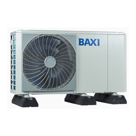
- Page 3 Baxi HP40/HP50 Monobloc Heat Pumps Warning The schematics below are based on the Baxi HP40/HP50 Monobloc Heat Pump range. See manufacturers instructions on how to connect the cylinder wiring to other heat pumps to ensure shut down of all heat sources in the event of a thermal cut out on the cylinder.
- Page 4 Baxi HP40/HP50 Monobloc Heat Pumps A = Main Hydraulic Control Board 7/8/11/13/ kW 4/5 kW Heat Pump PCB CN13 Adaptor CN24 CN21 CN28 CN16 CN32 CN13 CN15 CN29 CN18 CN25 CN42 CN40 DIS1 CN41 CN31 T5 Adaptor CN22 CN35 CN36...
- Page 5 Port group Identifier Port group Identifier (high voltage) CN30 Port group Identifier Fig. 3: Connection Layout “A” for Baxi HP40/HP50 Monobloc Heat Pumps 25 26 27 From A1 CN11 CN30 From A2 Connection of the immersion backup heater cable depends on the application. Only when the cylinder is installed will this wiring be needed.
- Page 6 Baxi HP40/HP50 Monobloc Heat Pumps Earth Neutral Live Fuse 16 - N 13 - TBH 1 3 5 7 25 26 27 Contactor CN11 CN30 Thermostat Controls 3 kW Immersion Backup Heater Fig. 5: Immersion Backup Heater SPINDLE POSITIONS THERMAL CUT-OUT RESET BUTTON...
- Page 7 Baxi HP40/HP50 Monobloc Heat Pumps DIP switches are located on the Main Hydraulic Control Board (‘A’ as shown on page 4) and allow configuration of Immersion Backup Heater. WARNING Switch off the power supply before opening the switch box service panel and making any changes to the DIP switch settings.
- Page 8 Unit F 5&6, Calmount Park, Calmount Road, Ballymount , Dublin 12, Ireland The policy of Baxi Heating UK is one of continuous product development and, as such, we reserve the right to change specifications and guarantee terms and conditions without notice. 7841138-02 (4/23)


Need help?
Do you have a question about the HP40 and is the answer not in the manual?
Questions and answers