
Subscribe to Our Youtube Channel
Related Manuals for AudioCodes MediaPack 1 Series


Summary of Contents for AudioCodes MediaPack 1 Series
- Page 1 Hardware Installation Manual AudioCodes MediaPack™ 1xx Analog VoIP Media Gateway Series MediaPack 124 (MP-124)
-
Page 3: Table Of Contents
Cabling the Device ................... 19 Power Surge Protection and Grounding Connections .......... 19 5.1.1 Device Connected to MDF through AudioCodes FXS Patch Panel ....... 21 5.1.2 Device Connected Directly to MDF ................. 22 Connecting Device to Ethernet Network .............. 23 Connecting Device to FXS Equipment .............. - Page 4 Figure 4-1: Desktop Mounting ....................... 17 Figure 4-2: Attached Brackets for Rack Installation ................17 Figure 5-1: Surge Protection and Grounding using AudioCodes FXS Patch Panel ......21 Figure 5-2: Surge Protection and Grounding Connected Directly to MDF ..........22 Figure 5-3: RJ-45 Connector Pinouts for Ethernet Interface ..............
-
Page 5: Weee Eu Directive
Customer Support Customer technical support and services are provided by AudioCodes or by an authorized AudioCodes Service Partner. For more information on how to buy technical support for AudioCodes products and for contact information, please visit our website at https://www.audiocodes.com/services-support/maintenance-and-support. -
Page 6: Regulatory Information
The device is supplied as a sealed unit and must only be serviced by qualified service personnel. Warning: Disconnect the device from the mains and Telephone Network Voltage (TNV) before servicing. Regulatory Information The Regulatory Information can be downloaded from AudioCodes website at https://www.audiocodes.com. Hardware Installation Manual Document #: LTRT-59850... - Page 7 Hardware Installation Manual Notices Document Revision Record LTRT Description 59815 Updates for Version 6.6. 59840 FXS warning statement added; power surge drawings updated. 59841 MP-124 Rev. E model added. 59842 Velcro hook-and-loop cable tie for Telco connector updated. 59843 Max. power consumptions updated. 59844 Channels LED numbers when SRTP enabled.
- Page 8 MP-124 Documentation Feedback AudioCodes continually strives to produce high quality documentation. If you have any comments (suggestions or errors) regarding this document, please fill out the Documentation Feedback form website https://online.audiocodes.com/documentation-feedback. Hardware Installation Manual Document #: LTRT-59850...
-
Page 9: Introduction
Hardware Installation Manual 1. Introduction Introduction This document provides a hardware description of the MediaPack MP-124 product (hereafter, referred to as device) and provides step-by-step instructions on cabling the device. Note: MP-124 Rev. E has replaced MP-124 Rev. D. • MP-124 Rev. - Page 10 MP-124 This page is intentionally left blank. Hardware Installation Manual Document #: LTRT-59850...
-
Page 11: Unpacking The Device
DC-powered model: unwired DC terminal block with two crimping screws Two short equal-length brackets and bracket-to-device screws for 19-inch rack • installation • Regulatory Information document Check, retain and process any documents. Notify AudioCodes or your local supplier of any damage or discrepancies. MediaPack Analog Gateways MP-124... - Page 12 MP-124 This page is intentionally left blank. Hardware Installation Manual Document #: LTRT-59850...
-
Page 13: Physical Description
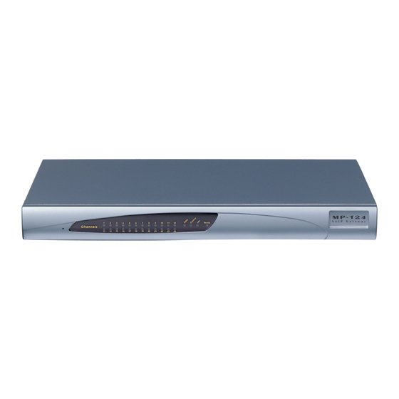
Hardware Installation Manual 3. Physical Description Physical Description This chapter provides a physical description of the device. Physical Dimensions and Operating Environment The device's physical dimensions and operating environment are listed in the table below: Table 3-1: Physical Dimensions and Operating Environment Physical Specification Description Dimensions (H x W x D) -
Page 14: Leds
MP-124 3.2.2 LEDs The LEDs on the front panel are described in the table below. Table 3-2: Front-Panel LED Descriptions Label Color State Function Ready Green Device powered on, self-test OK. Orange Blinking Software loading/initialization. Malfunction. Green Valid 10/100Base-TX Ethernet connection. Malfunction. -
Page 15: Rear Panel
Hardware Installation Manual 3. Physical Description Rear Panel The device's rear panel provides the port interfaces, as shown below and described in the subsequent table for the AC- and DC-powered models. AC-powered model: Figure 3-2: Rear Panel of AC-Powered Model DC-powered model: ... -
Page 16: Ethernet Led
MP-124 3.3.1 Ethernet LED The RJ-45 Ethernet port for Ethernet interface (labeled ETHERNET) provides LEDs that indicate Ethernet status, as described in the table below. Table 3-4: Rear-Panel Ethernet LED Description Label Color State Function ETHERNET Green Valid 10/100Base-TX Ethernet connection. Malfunction. -
Page 17: Mounting The Device
Hardware Installation Manual 4. Mounting the Device Mounting the Device The device can be mounted in one of the following ways: Desktop mounting – see 'Desktop Mounting' on page Installed in a standard 19-inch rack – see '19-inch Rack Mounting' on page ... - Page 18 MP-124 Rack Mount Safety Instructions When installing the chassis in a rack, implement the following safety instructions: Elevated Operating Ambient - If installed in a closed or multi-unit rack assembly, • consideration should be given to installing the equipment in an environment compatible with the maximum ambient temperature (Tma) of 40°C (104°F).
-
Page 19: Cabling The Device
Failing to install primary surge protectors, and failing to comply with the grounding instructions or any other installation instructions, may cause permanent damage to the device. As most of the installation is the responsibility of the customer, AudioCodes can • assume responsibility for damage only if the customer can establish that the device does not comply to the standards specified above (and the device is within the hardware warranty period). - Page 20 Fasten the cable securely using a 6-32 UNC screw. The grounding and lightning protection cabling setup for the device depends on whether AudioCodes orderable FXS Patch Panel (see Section 5.1.1) or a third-party MDF (see Section 5.1.2) is used. Hardware Installation Manual...
-
Page 21: Device Connected To Mdf Through Audiocodes Fxs Patch Panel
Device Connected to MDF through AudioCodes FXS Patch Panel The grounding and lightning protection cabling setup for connecting the device to the MDF through AudioCodes orderable FXS Patch Panel is shown below: Figure 5-1: Surge Protection and Grounding using AudioCodes FXS Patch Panel MediaPack Analog Gateways MP-124... -
Page 22: Device Connected Directly To Mdf
MP-124 5.1.2 Device Connected Directly to MDF The grounding and lightning protection cabling setup for connecting the device directly to a third-party MDF is shown below: Figure 5-2: Surge Protection and Grounding Connected Directly to MDF Hardware Installation Manual Document #: LTRT-59850... -
Page 23: Connecting Device To Ethernet Network
Hardware Installation Manual 5. Cabling the Device Connecting Device to Ethernet Network The procedure below describes how to connect the device directly to the Ethernet network. Cable: Crossover Ethernet cable Connector: RJ-45 Connector Pinouts: Figure 5-3: RJ-45 Connector Pinouts for Ethernet Interface ... -
Page 24: Connecting Device To Fxs Equipment
The device interfaces with the FXS analog telephone equipment (e.g., fax machines, modems, or telephones) through its 50-pin Telco connector. To connect to the equipment, you can use your own third-party, MDF connector cable or you can use AudioCodes' MP- 124 FXS Patch Panel (ordered separately from AudioCodes). -
Page 25: Connecting Fxs Interfaces Using Audiocodes Fxs Patch Panel
Figure 5-6: Orderable FXS Patch Panel 5.3.1 Connecting FXS Interfaces using AudioCodes FXS Patch Panel If you have purchased AudioCodes FXS Patch Panel, follow the instructions below for connecting the FXS analog equipment to the device through the Patch Panel. Note: The LEDs on the FXS Patch Panel front panel are disabled. -
Page 26: Figure 5-7: Connecting Device To Fxs Patch Panel
MP-124 Note: The following figure illustrates outdoor FXS cabling installations. For indoor FXS cabling installations, primary lightning protection is not required. Figure 5-7: Connecting Device to FXS Patch Panel Hardware Installation Manual Document #: LTRT-59850... -
Page 27: Connecting Fxs Interfaces Directly To Mdf
Hardware Installation Manual 5. Cabling the Device Connect your analog equipment to the Patch Panel, by plugging in each RJ-11 connector into the RJ-11 sockets on the Patch Panel's front panel: Figure 5-8: Connecting Analog Equipment to FXS Patch Panel 5.3.2 Connecting FXS Interfaces Directly to MDF If you are using your own third-party MDF, follow the instructions below for connecting the... -
Page 28: Figure 5-9: Connecting Device Directly To Mdf For Fxs Cabling
MP-124 Connect the telephone lines from the MDF to the analog equipment, by inserting each RJ-11 connector on the 2-wire line cords to the RJ-11 sockets on the front of the MDF: Figure 5-9: Connecting Device Directly to MDF for FXS Cabling Hardware Installation Manual Document #: LTRT-59850... -
Page 29: Securing Telco Cable To Connector With Velcro Strap
Telco cable, as described in the previous section. If you are using a Centronics cable that is anchored on one side, you can purchase a Velcro Strap Kit from AudioCodes to secure the cable to the device's Telco connector using a Velcro hook-and-loop cable tie (instead of using the connector's bail locks). -
Page 30: Figure 5-12: Attaching Bracket Over Telco Connector (E.g., Short Screws)
MP-124 connector. Keep the screws in a safe place for future use. Place the supplied bracket over the connector and then fasten it to the chassis using two screws. Depending on your cable connector requirements, use either the Hex. standoff screws, short Philips screws, or long Philips screws. Figure 5-12: Attaching Bracket over Telco Connector (e.g., Short Screws) Feed the Velcro strap through the two slots of the bracket, from the bottom slot to the top slot, with the Velcro side ("hooks") of the strap facing the chassis. -
Page 31: Figure 5-16: Pulling Velcro Strap To Reduce Slack Over Cable
Figure 5-18: Attaching Velcro Strap to Itself Follow the instructions described in this document to connect AudioCodes Mini Patch Panel to the device, and to the analog FXS lines. -
Page 32: Connecting Fxs Interfaces Using A Mini Patch Panel
MP-124 5.3.4 Connecting FXS Interfaces using a Mini Patch Panel You can connect the device's FXS lines to FXS equipment using an AudioCodes orderable Mini Patch Panel. Figure 5-19: Mini Patch Panel for FXS Interfaces Safety Notice To protect against electrical shock and fire, use 26 AWG minimum wire cabling to connect the Mini Patch Panel and to connect the analog FXS lines. -
Page 33: Figure 5-20: Connecting Fxs Lines Using Mini Patch Panel
Hardware Installation Manual 5. Cabling the Device Connect your analog equipment (for example, fax machines, modems, or telephones) by inserting each RJ-11 connector into the RJ-11 sockets on the front panel of the Mini Patch Panel (as shown in the figure below). Figure 5-20: Connecting FXS Lines using Mini Patch Panel Secure the Mini Patch Panel using the provided adhesive stickers or rest it on the rack shelf in a convenient position. -
Page 34: Connecting Device To Pc For Serial Communication
MP-124 Connecting Device to PC for Serial Communication The procedure below describes how to connect the device to a computer for serial RS-232 communication. The device provides serial interface through the RJ-45 port located on the rear panel: Cable adapter: straight-through RJ-45 to DB-9 cable (not supplied) ... -
Page 35: Figure 5-22: Connecting Device For Serial Communication
Hardware Installation Manual 5. Cabling the Device To connect the device to a computer for serial communication: Connect the RJ-45 connector, at one end of the cable adapter, to the device's RJ-45 port labeled ETHERENT, located on the rear panel. Figure 5-22: Connecting Device for Serial Communication Connect the DB-9 connector, at the other end of the cable adapter, to either the COM RS-232 communication port on your computer. -
Page 36: Connecting Device To Power
MP-124 Connecting Device to Power The device can be powered from either a standard AC electrical outlet or a -48V DC power source (depending on ordered model). Table 5-3: Power Specifications Physical Specification Description Power Supply Single universal power supply AC: 100-240 VAC, 50-60 Hz, 1A max Input Ratings ... -
Page 37: Ac Power Supply
Hardware Installation Manual 5. Cabling the Device 5.5.1 AC Power Supply This section describes how to connect the device to an AC electrical outlet. Warnings: The device must be connected only by professional service personnel. • Ensure that the device connects to an electrical socket outlet that provides protective •... -
Page 38: Dc Power Supply
MP-124 5.5.2 DC Power Supply This section describes how to connect the device to a -48V DC power source. DC Safety Notice When connecting the device to a DC power supply, ensure that you adhere to the following safety guidelines: •... - Page 39 Hardware Installation Manual 5. Cabling the Device This page is intentionally left blank. MediaPack Analog Gateways MP-124...
- Page 40 Website: https://www.audiocodes.com/ ©2019 AudioCodes Ltd. All rights reserved. AudioCodes, AC, HD VoIP, HD VoIP Sounds Better, IPmedia, Mediant, MediaPack, What’s Inside Matters, OSN, SmartTAP, User Management Pack, VMAS, VoIPerfect, VoIPerfectHD, Your Gateway To VoIP, 3GX, VocaNom, AudioCodes One Voice and CloudBond are trademarks or registered trademarks of AudioCodes Limited.
Need help?
Do you have a question about the MediaPack 1 Series and is the answer not in the manual?
Questions and answers