Table of Contents
Advertisement
Quick Links
Advertisement
Table of Contents

Related Manuals for Nibe SCU 10


Summary of Contents for Nibe SCU 10
- Page 1 MOS GB 1227-2 INSTALLATION AND MAINTENANCE INSTRUCTIONS SCU 10 SCU 10 031966...
-
Page 3: Table Of Contents
Components General information for the installer Component positions Docking List of components Inspection of the installation Dimensions Menu Settings Dimensions SCU 10 Set temp tank1 dTStart tank1 Electrical circuit diagram dTStop tank1 Technical specifications Min speed pump Extra heating Enclosed kit... -
Page 4: For Home Owners
For Home Owners General General NIBE SCU 10 is a control module designed to optimally control solar heating together with other heating equipment. Rights to make any design modifications are reserved. To be filled in when the product has been installed The serial number, must always be stated in all correspondence with NIBE. -
Page 5: System Description Principle Of Operation
System description System description Principle of operation options. With SCU 10 control the heat is spread from the solar panel to the heat store, i.e. the accumulator and is SCU 10 has been specially developed to work with NIBE's stored there when the sun is shining. The stored heat is then heat pumps and existing heating and hot water equipment. -
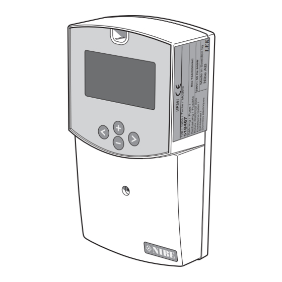
Page 6: Front Panel
4. Navigation buttons in menu. Keypad Forward button Navigate right Back button Navigate left Minus button Navigate down in the menu or minus (-). Plus button Navigate up in the menu or plus (+). SCU 10... -
Page 7: Settings Main Menu
Automatic". Activate the choice by pressing Stop operation in the same way, but on row "Off". 4 Menu Operating times ----------------- -- ----- Drifttider Drift _ _ h _ _°C Effekt _ _kW Energi _ _kWh Skicka PC SCU 10... -
Page 8: Control System
With this system you can choose to add extra functions with one or two sensors (Thermostat, Cooling or Diff. control function). _ _ _°C _ _ _°C _ _ _ % System SCU 10... - Page 9 With this system you can use extra functions with one sensor (Thermostat or Cooling function). _ _ _°C _ _ _°C _ _ _°C _ _ _ % _ _ _ % System SCU 10...
-
Page 10: Menus
Menu 1.13.4 [S] Sensor T4 Menu 1.13.5 [S] Sensor T5 Menu 1.14 [S] °C / °F Menu 1.15 [S] Pump P1 Menu 1.16 [S] Pump P2 Menu 1.17 [S] GDS1 NC Menu 1.18 [S] GDS2 NC Normal menus Service menus SCU 10... - Page 11 Menu 4.3 [N] Power Menu 4.4 [N] Energy Menu 4.5 [N] SD Card Menu 5.0 [N] Temperat- ures Menu 5.1 [N] Collector1 Menu 5.2 [N] Tank1 bottom Menu 5.3 [N] Tank top Menu 5.4 [N] Tank2 Normal menus Service menus SCU 10...
-
Page 12: For The Installer
For the Installer General information for the installer General information for the installer SCU 10 used when docking solar heating to your heating NOTE system. For control to start working, it must be activated in the operating menu. Work behind panels secured by screws may only be carried out by a qualified installation engineer. -
Page 13: Menu Settings
Setting of hysteresis to stop cooling function. Cooling is Hastighetsområde / 2 stopped when the temperature at the top of the tank (T3) is below "Cooling start" minus "Hysteresis". (Ad- justable 1 °C to 30 °C with default value 10 °C.) SCU 10... -
Page 14: Difference Control Function (Diff. Controls)
48 hours with default value 1 hour) again below the set value "Cooling start". This continues Press a few times to return to the main menu. until the tank temperature goes down to "Cooling stop". SCU 10... -
Page 15: Manual Test
The function also allows the Press a few times to return to the main menu. transfer of heat to other heat storage (e.g. pool). Example Extra Funktion styr pump att värma upp pool SCU 10... -
Page 16: Vacuum Pipe
The pump stops when the temperature in the tank has collector. dropped to the set maximum level or the temperature differ- ence between the tank and solar panel is less than 2 °C. SCU 10... -
Page 17: Flow Meter
(+) or (-). (Adjustable 1 to 25 l/pulse with default value 10 l/pulse.) If a pulse flow meter is used for energy measurement, you should install a T5 sensor on the return to the collect- or, to obtain a more accurate energy measurement. SCU 10... -
Page 18: Reset Operating Time
To return to the main menu press a few times. Sensor calibration Kalibrering givare Givare T1 Givare T2 Givare T3 Givare T4 Givare T5 In this sub menu it is possible to calibrate all temperature sensors in the system. SCU 10... -
Page 19: Prioritised Tank
When the prioritised tank reaches the maximum temper- ature (according to the setting) charging switches back to fully charge the non-prioritised tank. SCU 10... -
Page 20: Miscellaneous
. There are ten different systems to choose three sensors. between. _ _ _°C System selection can occur during 15 minutes after SCU 10 _ _ _ °C _ _ _°C has been powered. It is not possible to change the system, _ _ _ % until the voltage is switched off and on it again. - Page 21 _ _ _°C _ _ _°C _ _ _ % System Menu 2.0 [S] Settings Menu 2.1 [N] Set temp tank1 System 8 Menu 2.2 [N] dTStart tank1 Menu 2.3 [N] dTStop tank1 Menu 2.4 [N] Legionella protec- tion SCU 10...
-
Page 22: Menus
Menu 1.13.4 [S] Sensor T4 Menu 1.13.5 [S] Sensor T5 Menu 1.14 [S] °C / °F Menu 1.15 [S] Pump P1 Menu 1.16 [S] Pump P2 Menu 1.17 [S] GDS1 NC Menu 1.18 [S] GDS2 NC Normal menus Service menus SCU 10... - Page 23 Menu 4.3 [N] Power Menu 4.4 [N] Energy Menu 4.5 [N] SD Card Menu 5.0 [N] Temperat- ures Menu 5.1 [N] Collector1 Menu 5.2 [N] Tank1 bottom Menu 5.3 [N] Tank top Menu 5.4 [N] Tank2 Normal menus Service menus SCU 10...
-
Page 24: Dealing With Malfunctions
Cut the current before working on the installation. Troubleshooting If the operational interference is not shown in the display the following tips can be used: Group and main fuses of the accommodation. The property's earth circuit breaker. SCU 10 fuse. SCU 10... -
Page 25: Components Component Positions
Miscellaneous Components Components Component positions List of components Terminal block, power supply Terminal block, pumps Terminal blocks, sensors SCU 10... -
Page 26: Dimensions Dimensions Scu
Miscellaneous Dimensions Dimensions Dimensions SCU 10 SCU 10... -
Page 27: Electrical Circuit Diagram
Miscellaneous Electrical circuit diagram Electrical circuit diagram SCU 10... -
Page 28: Technical Specifications
1039 ohm 80 °C 1309 ohm 20 °C 1077 ohm 90 °C 1347 ohm 30 °C 1116 ohm 100 °C 1385 ohm 40 °C 1155 ohm 120 °C 1461 ohm 50 °C 1194 ohm 140 °C 1535 ohm SCU 10... -
Page 29: Enclosed Kit Temperature Sensor
Miscellaneous Enclosed kit Enclosed kit Temperature sensor 1 x high temperature sensor (red) 3 x low temperature sensor (grey) SCU 10... - Page 30 SCU 10...
- Page 32 Puh: 09-274 697 0 Fax: 09-274 697 40 E-mail: info@nibe.fi www.nibe.fi AIT France, Parc d'activités économique "Les Couturiers",16 rue des couturières, 67240 Bischwiller Tel : 03 88 06 24 10 Fax : 03 88 06 24 11 E-mail: info@nibe.fr www.nibe.fr NIBE Energy Systems Ltd, 3C Broom Business Park, Bridge Way, Chesterfield S41 9QG Tel: 0845 095 1200 Fax: 0845 095 1201 E-mail: info@nibe.co.uk www.nibe.co.uk...
Need help?
Do you have a question about the SCU 10 and is the answer not in the manual?
Questions and answers