Table of Contents
Advertisement
Advertisement
Table of Contents

Related Manuals for Nibe SAM 42


Summary of Contents for Nibe SAM 42
- Page 1 IHB EN 2119-1 INSTALLER MANUAL 631195 Supply air module SAM 42...
-
Page 3: Table Of Contents
General pipe connections Heating medium side Installation alternative General ventilation connection Ventilation flow Adjusting ventilation Dimension and ventilation connections 5 Electrical connections Supply Connecting communication 6 Commissioning and adjusting Preparations Filling and venting Start-up and inspection SAM 42 Table of Contents... -
Page 4: Important Information
1 Important information If the supply cable is damaged, only NIBE, Safety information its service representative or similar author- ised person may replace it to prevent any This manual describes installation and service proced- danger and damage. ures for implementation by specialists. -
Page 5: General
To access the separate components, refer to the section that shows the construction of the product. No special tools are required for access. Improper disposal of the product by the user results in administrative penalties in accordance with current le- gislation. SAM 42 Chapter 1 | Important information... - Page 6 Setting ventilation flow supply air Heating medium (page System flushed Accessories bled Check against output and pressure drop diagrams Connected according to outline dia- gram Electricity (page Supply connected 230 V Connected communication Chapter 1 | Important information SAM 42...
-
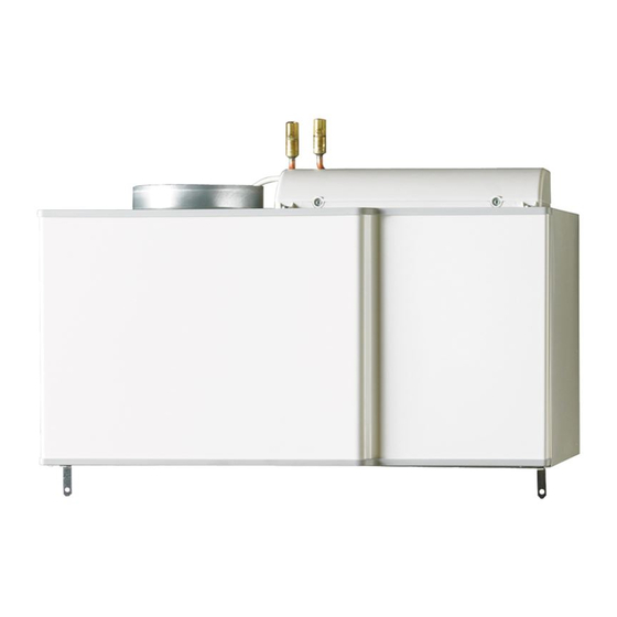
Page 7: Delivery And Handling
INSTALLATION AREA Leave a free space of 800 mm in front of the supply air module. All service on SAM 42 can be carried out from the front. SAM 42 Chapter 2 | Delivery and handling... -
Page 8: Removing The Covers
Removing the covers FRONT COVER Remove the service cover by pulling it straight out. Install SAM 42 from the top and slide into position. Mounting INSTALLING ON BRACKETS Install SAM 42 on brackets (accessory BAU 40) as illustrated below. Connect heating medium pipes and ventilation ducts. -
Page 9: The Design Of The Supply Air Module
BT69 BT68 QM20.1 QM20.2 XL33 BT22 XL34 BT23 HQ11 AA100 EP13 XL37 XL36 AA5-S2 XL33 QM20 XL34 QN40 W102 W101 HQ11 EP13 XL37 XL36 Svenskt produktblad Svenskt produktblad SAM 42 Chapter 3 | The design of the supply air module... -
Page 10: Pipe Connections
Sensors etc. Miscellaneous BT22 Temperature sensor, supply air Rating plate BT23 Temperature sensor, outdoor air Designations according to standard EN 81346-2. BT68 Temperature sensor, flow BT69 Temperature sensor, return Chapter 3 | The design of the supply air module SAM 42... -
Page 11: Pipe And Ventilation Connections
NOTE at the end of the manual. External frost protection (outdoor air damper) SYMBOL KEY should be installed in the outdoor air duct, if SAM 42 is installed in a cold climate. Symbol Meaning Expansion vessel SAM 42 SAM 40... -
Page 12: Heating Medium Side
Vattenflöde 1400 1200 The diagram shows the climate system’s required 1000 pressure drop. The pressure drop across SAM 42 is the same as that across the climate system that is parallel with SAM 42. 53 l/s 36 l/s Check that the working point is inside the grey area. If... -
Page 13: Installation Alternative
Installation alternative General ventilation connection SAM 42 can be installed in several different ways, some of which are shown here. Further option information is available at nibe.eu/ODM • Ventilation installation must be carried out in accord- and in the respective assembly instructions for the ac- ance with current norms and directives. -
Page 14: Adjusting Ventilation
Incorrect adjustment of the ventilation may lead to re- duced installation efficiency and thus poorer operating economy, a poorer indoor climate and moisture damage in the building. Dimension and ventilation connections Supply air Outdoor air Ø160 Chapter 4 | Pipe and ventilation connections SAM 42... -
Page 15: Electrical Connections
Supply SAM 42 is connected to a earthed single-phase wall socket or a permanent installation. For permanent install- ations, SAM 42 must be preceded by a circuit breaker with at least a 3 mm breaking gap. SAM 42 Chapter 5 | Electrical connections... - Page 16 For connection of external frost protection (outdoor air damper), see the Installer Manual for the main product. DIP SWITCH The DIP-switch (S2) on the accessory board (AA5) is set in the factory as below. Chapter 5 | Electrical connections SAM 42...
-
Page 17: Commissioning And Adjusting Preparations
FILLING THE CLIMATE SYSTEM Fill with water using the filler valve in the heat pump. VENTING THE CLIMATE SYSTEM Vent SAM 42 through the vent valves (QM20.1), (QM20.2) and the rest of the climate system through its respective vent valves. -
Page 18: Start-Up And Inspection
The setting is made in menu 5.1.6. Even if ventilation is roughly set at installation it is im- portant that a ventilation adjustment is ordered and permitted. NOTE Order a ventilation adjustment to complete the setting. Chapter 6 | Commissioning and adjusting SAM 42... -
Page 19: Program Settings
°C Caution This accessory may require a program software update in your heat pump. The heat pump must have software version 8432R2 (F370) or later. SAM 42 Chapter 7 | Program settings... -
Page 20: Disturbances In Comfort
SAM 42 is connected. • Air in the heating medium system. • Group and main fuses of the accommodation. – Vent SAM 42 using vent valve (QM20.1) and (QM20.2). • The property's earth circuit breaker. • Incorrect value set in supply air automatic control LOW HOT WATER TEMPERATURE OR A system. -
Page 21: Accessories
Detailed information about the accessories and complete accessories list available at nibe.eu. Not all accessories are available on all markets. BRACKET BAU 40 Wall mounting of SAM 42. Part no. 067 666 BUFFER VESSEL UKV A buffer vessel is an accumulator tank that is suitable for connection to a heat pump or another external heat source, and can have several different applications. -
Page 22: Technical Data
10 Technical data Dimensions and setting-out coordinates Ø22 Ø160 Chapter 10 | Technical data SAM 42... -
Page 23: Technical Specifications
Part No. 067 759 The value varies with the selected fan curve. For more detailed sound data, including sound to channels, visit nibe.eu. The value can vary with the room’s damping capacity. These values apply at a damping of 4 dB. -
Page 24: Electrical Circuit Diagram
Electrical circuit diagram Chapter 10 | Technical data SAM 42... -
Page 26: Contact Information
Tel: +46 (0)433-27 3000 info@evan.ru info@nibe.se nibe-evan.ru nibe.se SWITZERLAND NIBE Wärmetechnik c/o ait Schweiz Industriepark, CH-6246 Altishofen Tel. +41 (0)58 252 21 00 info@nibe.ch nibe.ch For countries not mentioned in this list, contact NIBE Sweden or check nibe.eu for more information. - Page 27 WS release date: 2021-05-12 12:03 Publish date: 2021-05-26 14:20 This manual is a publication from NIBE Energy Systems. All product illustrations, facts and data are based on the available information at the time of the publication’s approval. NIBE Energy Systems makes reservations for any factual or printing errors in this manual.
- Page 28 Publication Warnings At translation (TP-3699): Förklaring till symboler som kan förekomma i den... At translation (TP-3700): Förklaring till symboler som kan förekomma på pr... Publication Warnings SAM 42...
Need help?
Do you have a question about the SAM 42 and is the answer not in the manual?
Questions and answers