Avaya Ethernet Routing Switch 8300 Series Installation Manual
Chassis
Hide thumbs
Also See for Ethernet Routing Switch 8300 Series:
- Quick start manual (52 pages) ,
- Planning and engineering (44 pages) ,
- Installation manual (50 pages)

Related Manuals for Avaya Ethernet Routing Switch 8300 Series


Summary of Contents for Avaya Ethernet Routing Switch 8300 Series
- Page 1 Installation — Chassis Avaya Ethernet Routing Switch 8300 NN46200-309,02.02 May 2011...
- Page 2 Avaya or the applicable third party. Avaya does not guarantee that these links will work all the time and has no control over the availability of the linked pages.
-
Page 3: Table Of Contents
Contents Chapter 1: Regulatory Information and Safety Precautions..........5 International Regulatory Statements of Conformity..................5 National Electromagnetic Compliance (EMC) Statements of Compliance............5 ICES Statement (Canada only).........................6 CE Marking Statement (Europe only).......................6 VCCI Statement (Japan/Nippon only).......................7 BSMI Statement for 8310, and 8306 Chassis (Taiwan only)................8 MIC notice for 8310, and 8306 chassis (Republic of Korea only)..............8 National Safety Statements of Compliance.......................8 NOM Statement 8310 and 8306 Chassis (Mexico only)...................9... - Page 4 Chapter 7: Customer Service....................49 Getting technical documentation........................49 Getting product training...........................49 Getting help from a distributor or reseller......................49 Getting technical support from the Avaya Web site..................50 Chapter 8: Translations of safety messages................51 Class A device caution statement ........................51 Electrostatic discharge caution statement.......................52 Chapter 9: Part Numbers......................55...
-
Page 5: Chapter 1: Regulatory Information And Safety Precautions
Read the information in this section to learn about regulatory conformities and compliances. International Regulatory Statements of Conformity This is to certify that the Avaya 8300 Series chassis and components installed within the chassis were evaluated to the international regulatory standards for electromagnetic... -
Page 6: Ices Statement (Canada Only)
CE Marking Statement (Europe only) EN 55 022 Statements This is to certify that the Avaya 8300 Series chassis and components installed within the chassis are shielded against the generation of radio interference in accordance with the application of Council Directive 2004/108/EC. Conformity is declared by the application of EN 55 022 Class A (CISPR 22). -
Page 7: Vcci Statement (Japan/Nippon Only)
VCCI Statement (Japan/Nippon only) EN 55 024 Statement This is to certify that the Avaya 8300 Series chassis is shielded against the susceptibility to radio interference in accordance with the application of Council Directive 2004/108/EC. Conformity is declared by the application of EN 55 024 (CISPR 24). -
Page 8: Bsmi Statement For 8310, And 8306 Chassis (Taiwan Only)
CE Marking Statement (Europe only) EN 60 950 Statement This is to certify that the Avaya 8300 Series chassis and components installed within the chassis are in compliance with the requirements of EN 60 950 in accordance with the Low Voltage Directive. -
Page 9: Nom Statement 8310 And 8306 Chassis (Mexico Only)
The following information is provided on the devices described in this document in compliance with the safety requirements of the Norma Oficial Méxicana (NOM): Exporter: Avaya, Inc. 4655 Great American Parkway, Santa Clara CA 95054 Importer: Avaya Communication de Mexico, S.A.de C.V.Av. Presidente Masarik 111 Pisco 6 Col Chapultepec Morales Deleg. -
Page 10: Denan Statement (Japan/Nippon Only)
Denan Statement (Japan/Nippon only) Safety Messages This section describes the different precautionary notices used in this document. This section also contains precautionary notices that you must read for safe operation of the Avaya Ethernet Routing Switch 8300. Notices Notice paragraphs alert you about issues that require your attention. The following sections describe the types of notices. - Page 11 Electrostatic alert: PRECAUCIÓN ESD (Descarga electrostática) El aviso de ESD brinda información acerca de cómo evitar una descarga de electricidad estática y el daño posterior a los productos Avaya. Electrostatic alert: CUIDADO ESD Os avisos do ESD oferecem informações sobre como evitar descarga de eletricidade estática e os conseqüentes danos aos produtos da Avaya.
- Page 12 Schäden an Avaya-Produkten verhindert. Caution: PRECAUCIÓN Los avisos de Precaución brindan información acerca de cómo evitar posibles interrupciones del servicio o el daño a los productos Avaya. Caution: CUIDADO Os avisos de cuidado oferecem informações sobre como evitar possíveis interrupções do serviço ou danos aos produtos da Avaya.
- Page 13 Safety Messages Warning: AVERTISSEMENT La mention Avertissement fournit des informations sur les moyens de prévenir les risques de blessure lors de la manipulation de produits Avaya. Warning: WARNUNG Warnhinweise bieten Informationen dazu, wie man Personenschäden bei der Arbeit mit Avaya-Produkten verhindert.
- Page 14 Regulatory Information and Safety Precautions Hinweise mit „Vorsicht – Hochspannung“ bieten Informationen dazu, wie man Situationen oder Umstände verhindert, die zu schweren Personenschäden oder Tod durch Hochspannung oder Stromschlag führen können. Voltage: PELIGRO Los avisos de Peligro-Alto voltaje brindan información acerca de cómo evitar una situación o condición que cause graves lesiones a personas o la muerte, a causa de una electrocución o de una descarga de alto voltaje.
- Page 15 Safety Messages Danger: PERIGO Avisos de perigo oferecem informações sobre como evitar uma situação ou condição que possa causar graves ferimentos ou morte. Danger: PERICOLO Le indicazioni di pericolo forniscono informazioni per evitare situazioni o condizioni che potrebbero causare gravi danni alle persone o il decesso. Installation —...
- Page 16 Regulatory Information and Safety Precautions Installation — Chassis May 2011...
-
Page 17: Chapter 2: New In This Release
Chapter 2: New in this release The following sections detail what's new in Avaya Ethernet Routing Switch 8300 Installation — Chassis , NN46200-309 for Release 4.2: • Features on page 17 • Other changes on page 17 Features This document has no feature updates for the Release 4.2. - Page 18 New in this release Customer service Customer service chapter is added to this document. This chapter describes the complete range of services and support that Avaya provides to its customers. For more information about Avaya support, see Customer Service chapter. Installation — Chassis...
-
Page 19: Chapter 3: Introduction
This document provides the instructions for installing the Avaya Ethernet Routing Switch 8300 chassis (8306 and 8310 chassis) in an equipment rack. This document also describes some of the routine tasks that you use to operate the Avaya Ethernet Routing Switch 8300 and includes technical specifications for the chassis and modules. - Page 20 Introduction Installation — Chassis May 2011...
-
Page 21: Chapter 4: Chassis Installation Fundamentals
This chapter describes fundamental information that you need for installing the Avaya Ethernet Routing Switch 8300 chassis (8306 and 8310 chassis) . Each Avaya Ethernet Routing Switch 8300 chassis consists of a sheet metal enclosure and a backplane. The number of bays for fan trays depends on the chassis type. - Page 22 Risk of equipment damage Do not install Ethernet Routing Switch 8300 modules and Ethernet Routing Switch 8100 or 8800/8600 modules within the same chassis. Ethernet Routing Switch 8300 Series software does not support mixed configurations. A mixed configuration can damage the modules and void your warranty.
-
Page 23: Ethernet Routing Switch 8306 Chassis
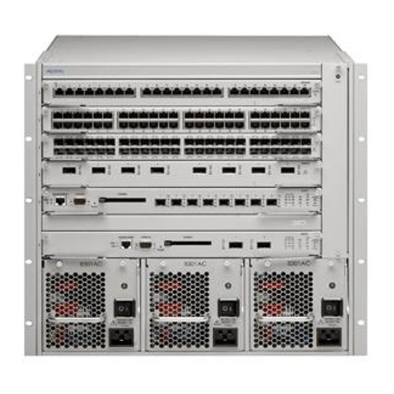
Ethernet Routing Switch 8306 chassis Figure 1: Ethernet Routing Switch 8310 chassis and components Ethernet Routing Switch 8306 chassis The Ethernet Routing Switch 8306 chassis provides four slots for installing I/O modules and two slots for installing Ethernet Routing Switch 8393SF/CPU or 8394SF/CPU modules. See Figure 2: 8306 chassis and components on page 24. -
Page 24: Power Supplies
Risk of equipment damage Do not install Ethernet Routing Switch 8300 modules and Ethernet Routing Switch 8100 or 8800/8600 modules within the same chassis. Ethernet Routing Switch 8300 Series software does not support mixed configurations. A mixed configuration can damage the modules and void your warranty. -
Page 25: Fan Trays
A control/monitor circuit board in the fan tray reports temperature and fan operating status to the network management software. A green light emitting diode (LED) indicates that the fan tray is operating correctly. For information about installing the fan, see Avaya Ethernet Routing Switch 8300 Installation — Fan Tray (NN46200-302). -
Page 26: Hardware Requirements
Refer to the power specifications for the power supply in Technical specifications page 57. For AC input power specifications for each of the modules, see Avaya Ethernet Routing Switch 8300 Installation — Modules (NN46205-305). Environmental requirements The installation site must meet the following environmental requirements for 8300 chassis operation. - Page 27 Hardware requirements Shipment contents In addition to the Ethernet Routing Switch 8310 or 8306 chassis, your shipping container contains several hardware accessories. Verify that the items in the shipping container match those on the shipment packing list. The following table is a checklist of items included in the shipment container. For information about ordering replacement parts, see Part Numbers on page 55.
- Page 28 Chassis installation fundamentals Figure 3: Items in the Ethernet Routing Switch 8310 chassis shipping container Installation — Chassis May 2011...
-
Page 29: Other Equipment
Other equipment Figure 4: Items in the Ethernet Routing Switch 8306 chassis shipping container Other equipment In addition to the items that are included in the Ethernet Routing Switch 8310 and 8306 chassis accessory package you must also supply other items. Before you install the hardware, ensure that you have all the cables, tools, and other equipment that you need. -
Page 30: Successful Installation Verification
In a normal power-up sequence, the LEDs light as follows: 1. When power is applied to the Ethernet Routing Switch 8300 Series, the green LED on each power supply and fan tray turns on, and the Online LED for each module lights amber. -
Page 31: Chapter 5: Ethernet Routing Switch 8310 And 8306 Chassis Installation
• Inspect all items for shipping damage. If you detect damage, do not install the chassis. Call the Avaya Technical Solutions Center in your area. • Verify that the items in the shipping container match those on the shipment packing list. -
Page 32: Navigation
Ethernet Routing Switch 8310 and 8306 chassis installation Navigation • Chassis installation time requirements on page 33 • Reducing the chassis weight on page 33 • Installing the chassis on a flat surface on page 34 Installation — Chassis May 2011... -
Page 33: Chassis Installation Time Requirements
38 Chassis installation time requirements The following table lists procedures you must use to install the Avaya Ethernet Routing Switch 8300 chassis and the estimated time you need to complete each procedure. Not all procedures are required for every Avaya Ethernet Routing Switch 8300 system. -
Page 34: Installing The Chassis On A Flat Surface
Ethernet Routing Switch 8310 and 8306 chassis installation Installing the chassis on a flat surface Mount the Ethernet Routing Switch 8310 and 8306 chassis on any flat, level surface, such as a tabletop or shelf, that can safely support the weight of the chassis, its components, and its attached cables to provide a convenient location for the safe operation of the switch. -
Page 35: Mounting The Ethernet Routing Switch 8310 And 8306 Chassis In An Equipment Rack
Mounting the Ethernet Routing Switch 8310 and 8306 chassis in an equipment rack Mounting the Ethernet Routing Switch 8310 and 8306 chassis in an equipment rack Install the Ethernet Routing Switch 8310 and 8306 chassis in a standard 19-inch equipment rack to provide a convenient location for the safe operation of the switch. - Page 36 Ethernet Routing Switch 8310 and 8306 chassis installation 2. Insert and tighten the supplied flat-head screws to fasten each bracket to the chassis. Installation — Chassis May 2011...
- Page 37 Mounting the Ethernet Routing Switch 8310 and 8306 chassis in an equipment rack 3. Measure the appropriate number of rack units of free vertical space inside the rack and mark the spot. The following table shows the number of rack units you can allocate for each chassis.
-
Page 38: Installing The Cable Guides
Ethernet Routing Switch 8310 and 8306 chassis installation Procedure job aid: Maximum number of chassis installed in 7-foot rack The following table shows the maximum number of chassis that you can install in a 7-foot rack. Chassis Maximum number of chassis installed in 7-foot rack 8310 8306 Installing the cable guides... - Page 39 Installing the cable guides Procedure steps 1. Loosen, but do not remove, the rack-mounting screws needed to install one cable guide. 2. Slide the guide onto the loosened screws. 3. Tighten the screws to secure the guide to the chassis. Installation —...
- Page 40 Ethernet Routing Switch 8310 and 8306 chassis installation Installation — Chassis May 2011...
-
Page 41: Chapter 6: Switch Operations
Chapter 6: Switch operations This chapter describes some of the procedures that you perform to operate the Ethernet Routing Switch 8300 and provides troubleshooting information. Navigation • Powering on DC power supplies on page 41 • Powering on AC power supplies on page 42 •... -
Page 42: Powering On Ac Power Supplies
5. If the power supply LED remains off, or if you cannot feel air flow from the chassis vents, turn the DC power supplies off, and then turn them on again. 6. If the problem persists, contact the Avaya Technical Solutions Center. Powering on AC power supplies Power on the AC power supplies to provide power to the switch. -
Page 43: Resetting The Switch
Resetting the switch Reset the switch to reboot the switch hardware without cycling power. Procedure steps To warm-start the Ethernet Routing Switch 8300 Series (no diagnostic tests are run), press the Reset button for less than 5 seconds. Installation — Chassis... -
Page 44: Installing Removable Flash Memory Cards
Switch operations To press the Reset button, insert a small pointed object (for example, an unbent paper clip) into the Reset button hole. The following figure shows the location of the Reset button on the Ethernet Routing Switch 8393SF/CPU module. Figure 5: Reset button on the 8393SF/CPU module The following figure shows the location of the Reset button on the Ethernet Routing Switch 8394SF/CPU module. -
Page 45: Removing Removable Flash Memory Cards
Removing removable flash memory cards 2. Insert the card into the card receptacle. 3. Gently push the card in until it fits snugly in place. Removing removable flash memory cards Remove a removable flash memory card from the Ethernet Routing Switch 8393SF/CPU or 8394SF/CPU module to stop using it as a storage medium. -
Page 46: Protecting Memory Card Files
Protecting memory card files Write-protect the memory card for backup purposes after you successfully load the configuration file and save your configuration because Avaya ships each memory card with the read-write protect switch in the unprotected position. Typically, you do not operate the switch with a write-protected memory card. Make a copy of your configuration on another memory card, write-protect that card, and store it in a safe place. -
Page 47: Troubleshooting
Troubleshooting 3. Adjust the read-write protect switch. 4. Reinsert the memory card into the card receptacle. Troubleshooting The following sections provide troubleshooting information for some of the more common problems that you can encounter with the Ethernet Routing Switch 8300. LED indications of problems Table 4: LED problem indicators on page 47 lists possible problems indicated by the LEDs... - Page 48 Cabling for 10BASE-T networks can consist of two-pair Category 3, 4, or 5 unshielded twisted pair (UTP) wiring. However, to prepare for future upgrades to Fast Ethernet, Avaya strongly recommends that you use all Category 5 cable in your network.
-
Page 49: Chapter 7: Customer Service
Chapter 7: Customer Service Visit the Avaya Web site to access the complete range of services and support that Avaya provides. Go www.avaya.com or go to one of the pages listed in the following sections. Navigation • Getting technical documentation on page 49 •... -
Page 50: Getting Technical Support From The Avaya Web Site
Customer Service Getting technical support from the Avaya Web site The easiest and most effective way to get technical support for Avaya products is from the Avaya Technical Support Web site at www.avaya.com/support. Installation — Chassis May 2011... -
Page 51: Chapter 8: Translations Of Safety Messages
Chapter 8: Translations of safety messages Class A device caution statement Caution: This device is a Class A product. Operation of this equipment in a residential area is likely to cause harmful interference, in which case users are required to take appropriate measures necessary to correct the interference at their own expense. -
Page 52: Electrostatic Discharge Caution Statement
Translations of safety messages Caution: ATTENZIONE Questo dispositivo è un prodotto di Classe A. Il funzionamento di questo apparecchio in aree residenziali potrebbe causare interferenze dannose, nel cui caso agli utenti verrà richiesto di adottare tutte le misure necessarie per porre rimedio alle interferenze a proprie spese. - Page 53 Electrostatic discharge caution statement Para evitar danos com descarga eletrostática, sempre use uma pulseira antiestática que esteja conectada a uma tomada de descarga eletrostática (ESD) quando estiver realizando a manutenção deste produto. Certifique-se de que a pulseira esteja em contato com sua pele.
- Page 54 Translations of safety messages Installation — Chassis May 2011...
-
Page 55: Chapter 9: Part Numbers
Chapter 9: Part Numbers This chapter provides a list of Avaya Ethernet Routing Switch 8300 hardware and part numbers. The following table lists Avaya Ethernet Routing Switch 8300 hardware and part numbers. Table 5: Ethernet Routing Switch 8300 hardware part numbers... - Page 56 Part Numbers Part number Item Additional details 10BASE-T/100BASE-TX ports Ethernet interface module DS1404079-E5 Ethernet Routing Switch 8324GTX module, 24 port autonegotiating (10BASE-T, 100BASE-TX, or 1000BASE-T) Ethernet interface module DS1404098-E5 Ethernet Routing Switch 8324FX. 24 Port 100Base-FX Ethernet interface module DS1404093-E5 Ethernet Routing Switch 8348GTX module.
-
Page 57: Chapter 10: Technical Specifications
Chapter 10: Technical specifications This chapter lists the physical, environmental, and electrical specifications for the Ethernet Routing Switch 8310 and 8306 chassis and the available power supplies. Navigation • Ethernet Routing Switch 8310 chassis specifications on page 57 • Ethernet Routing Switch 8306 chassis specifications on page 59 •... - Page 58 Technical specifications Physical specifications Weight (fully loaded): 225 lb (102 kg) Cooling system: Fan trays: 2 per chassis Fans: 8 per fan tray Thermal sensors: 1 per fan tray Environmental specifications The following table lists the environmental specifications of the Ethernet Routing Switch 8310 chassis.
-
Page 59: Ethernet Routing Switch 8306 Chassis Specifications
Ethernet Routing Switch 8306 chassis specifications International regulatory requirements Global basis for certification: CISPR 22-1997 Class A U.S.: FCC CFR47 Part 15, Subpart B, Class A Canada: ICES-003, Issue-2, Class A Europe: EN 55022-1998 Class A; EN 61000-3-2/A14, EN 61000-3-3 (CE Marking Australia/New Zealand: AS/NZS 3548:1995, Class A Japan:... - Page 60 Technical specifications Table 9: Ethernet Routing Switch 8306 physical specifications Physical specifications Height: 15.8 in. (40.1 cm) Width: 17.5 in. (44.5 cm) Depth: 19.9 in. (50.5 cm) Weight (empty): 49 lb (22 kg) Weight (fully loaded): 140 lb (63 kg) Cooling system: Fan tray: 1 per chassis...
-
Page 61: Ethernet Routing Switch 8301 Ac Power Supply Specifications
Ethernet Routing Switch 8301 AC power supply specifications Table 11: Ethernet Routing Switch 8306 international regulatory requirements International regulatory requirements Electromagnetic emissions regulatory requirements: Global basis for CISPR 22-1997 Class A certification: U.S.: FCC CFR47 Part 15, Subpart B, Class A Canada: ICES-003, Issue-2, Class A Europe:... - Page 62 Technical specifications Table 12: Ethernet Routing Switch 8301 AC power specifications AC Input Power Ratings Input voltage range (nominal): 100-120 VAC 200-240 VAC Input current (nominal): 16 amperes (A) 12 A Frequency range (nominal): 50-60 Hertz (Hz) 50-60 Hz Input VA 1600 volt-amperes VA 2234 VA Input power consumption:...
-
Page 63: Ethernet Routing Switch 8302 Ac Power Supply Specifications
Ethernet Routing Switch 8302 AC power supply specifications Ethernet Routing Switch 8302 AC power supply specifications The following table lists the power specifications for the 8302 AC power supply. Table 13: Ethernet Routing Switch 8302 AC power specifications AC Input Power Ratings Input voltage range (nominal): 100-120 VAC 200-240 VAC... -
Page 64: Ethernet Routing Switch 8005Dc Power Supply Specifications
Technical specifications nominal input voltage conditions. This limitation is required to ensure maximum PoE power or 450 W total for the 50 VDC source at this input voltage condition. • To obtain the full output power rating of 1400 W, you must connect the power supply to a nominal (200-240VAC) input voltage source. - Page 65 Ethernet Routing Switch 8005DI DC power supply specifications Parameter Specifications Input voltage –40Vdc/–75Vdc Input current 48.75A /32.5A Input VA (maximum) 1.95 kVA Input power consumption 1950 W Heat dissipation (thermal/output) 1666 Btu/hr The following table lists the DC output power specifications. Parameter Specifications Output power (maximum)
- Page 66 Technical specifications Installation — Chassis May 2011...
-
Page 67: Index
Index flash memory card ..........preparing for ............cable Category 5 ............crossover ............. straight-through ............ LEDs troubleshooting ............ power supplies ............. cables problem indications ..........ordering ..............chassis components, described ........installing memory cards 8306 .............. changing read-write protection ......8310 .............. - Page 68 LED indications ............ Installation — Chassis May 2011...
Need help?
Do you have a question about the Ethernet Routing Switch 8300 Series and is the answer not in the manual?
Questions and answers