
Related Manuals for WAGNER Super Finish 33 PLUS


Summary of Contents for WAGNER Super Finish 33 PLUS
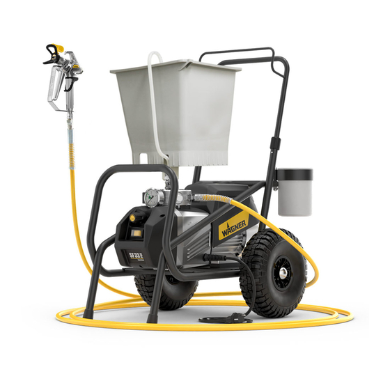
- Page 1 Service manual with electrical repair instructions for electri- cally instructed persons of the J. Wagner GmbH Super Finish 33 PLUS Super Finish 33 Pro Nespray Pro 2405146 B 06 / 2019...
- Page 2 1. Faulty units may not be used. 2. Secure a Wagner spray gun with the securing lever at the trigger guard. 3. Ensure earthing. 4. Check the permissible operating pressure of the high-pressure hose and spray gun.
-
Page 3: Table Of Contents
Super Finish 33 PLUS/PRO • Nespray Pro Contents SAFETY REGULATIONS FOR AIRLESS SPRAYING 4 4.11 Spare parts list of heating hose drum ___________ 32 Flash point ___________________________________4 4.12 Spare parts list of heating hose drum ___________ 34 Explosion protection ___________________________4... -
Page 4: Safety Regulations For Airless Spraying
Super Finish 33 PLUS/PRO • Nespray Pro SAFETY REGULATIONS FOR DANGER OF INJURY FROM THE SPRAY JET AIRLESS SPRAYING Attention, danger of injury by injection! Never point the spray gun at yourself, other persons or animals. All local safety regulations in force must be observed. -
Page 5: Max. Operating Pressure
Super Finish 33 PLUS/PRO • Nespray Pro 1.12 MAX. OPERATING PRESSURE USE OF UNITS ON BUILDING SITES AND WORKSHOPS The permissible operating pressure for the spray gun, spray gun accessories, unit accessories and high-pressure hose The unit may only be connected to the mains network via a... -
Page 6: Technical Data
Super Finish 33 PLUS/PRO • Nespray Pro TECHNICAL DATA Super Finish 33 Plus Super Finish 33 Pro Nespray Pro (Type: D701C) (Type: D702C) (Type: D703C) Voltage : 230 Volt ~, 50 Hz Fuses : 16 A träge Voltage on multifunction switch:... -
Page 7: Repairs At The Unit
Super Finish 33 PLUS/PRO • Nespray Pro REPAIRS AT THE UNIT INLET VALVE 1. Place the enclosed 30 mm wrench on the trigger housing Switch the unit off. (1). Before all repair work: Unplug the power 2. Loosen the trigger housing (1) with light blows of a ham- plug from the outlet. -
Page 8: Outlet Valve
Test medium: water The torque for fitting the outlet valve is 50 Nm. 5. Mount a pressure gauge (0 – 400 bar), an original pressure hose from Wagner and a high pressure airless gun. 10 (15 Nm) SETTING THE MAXIMUN OPERATING PRESSURE (CLOSING PRESSURE) 1. -
Page 9: Replacing The Power Cable
Super Finish 33 PLUS/PRO • Nespray Pro REPLACING THE POWER CABLE This may only be carried out by a skilled elec- trician. No liability is assumed for incorrect in- stallation. Switch the unit off. Before all repair work: Unplug the power plug from the outlet. -
Page 10: Checking The Oil Level
Super Finish 33 PLUS/PRO • Nespray Pro CHECKING THE OIL LEVEL 1. Check oil level in the horizontal set-up. 2. The oil level must be in the middle between MIN and MAX. When filling, briefly lift the device (tilt it up- wards by approx. - Page 11 Super Finish 33 PLUS/PRO • Nespray Pro TYPE OF WHAT ELSE? POSSIBLE CAUSE MEASURES FOR ELIMINATING THE MALFUNCTION MALFUNCTION Delivery rate too Most likely -> Inlet or outlet valve dam- Check and replace valves aged Material sucked up hardly Unit is sucking in air...
-
Page 12: Indicators At The Electric Console
Super Finish 33 PLUS/PRO • Nespray Pro INDICATORS AT THE ELECTRIC CONSOLE DESCRIPTION LED red (Indicator for voltage supply - lights up when there is voltage supply) LED green (Indicator for “ready for operation” – lights up when there is voltage supply and the thermal fuse is closed = means temperature of the motor is ok) LED yellow (Indicator for contactor –... - Page 13 LIGHTED SIGNS CONTROLER BOARD brown MOTOR Super Finish 33 PLUS/PRO • Nespray Pro WITH TEMPERATURE SWITCH white light blue light blue grey green/yellow blue Version SF 33 PLUS / Nespray Pro green/yellow 155°C SOFT START CONTROLLER black MICRO SWITCH black 2388610 C = 40µF...
-
Page 14: Spare Parts
Super Finish 33 PLUS/PRO • Nespray Pro SPARE PARTS SPARE PARTS LIST SF 33 PLUS / NESPRAY PRO (TAKEN FROM ENDUSER‘S MANUAL) ITEM ORDER-NO DESIGNATION ITEM ORDER-NO DESIGNATION 0340 339 Inlet 2383 937 Tool box with lid compl. (incl. items 33,... - Page 15 Super Finish 33 PLUS/PRO • Nespray Pro...
-
Page 16: Spare Parts List Sf 33 Pro (Taken From Enduser's Manual)
Super Finish 33 PLUS/PRO • Nespray Pro SPARE PARTS LIST SF 33 PRO (TAKEN FROM ENDUSER‘S MANUAL) ITEM ORDER-NO DESIGNATION 0340 339 Inlet 2337 033 Inlet valve trigger 0341 336 Clasp 0341 247 Inlet valve complete 2334 383 Inlet valve housing 2385 577 Inlet valve housing compl. - Page 17 Super Finish 33 PLUS/PRO • Nespray Pro...
-
Page 18: Additional Spare Parts Sf 33 Plus/Pro (Service Only)
Super Finish 33 PLUS/PRO • Nespray Pro ADDITIONAL SPARE PARTS SF 33 PLUS/PRO (SERVICE ONLY) To remove the pump, move ITEM ORDER-NO* DESIGNATION QUANTITY** it to an upright position. 9990535 Protective cap Open the oil lock screw to 2359803 Cylinder head screw M12x60... - Page 19 Super Finish 33 PLUS/PRO • Nespray Pro Tighten carefully cross- Explanation wise to avoid tilting pos. (xNm) indicates torque 6 (do not damage O- seal with UHU-Plus 2K (order-no. rings). 2 (70Nm) 28 (70Nm) Tighten crosswise. Then first tighten one of the two front screws (be sure to observe the torque).
- Page 20 Super Finish 33 PLUS/PRO • Nespray Pro ITEM ORDER-NO* DESIGNATION QUANTITY** 2390385 Front cover SF 33 PLUS assy. 2390424 Front cover SF 33 PRO assy. 9900353 Cylinder head screw M4x12 9952820 Capacitor 40µF/475V 9950244 Terminal strip 9950239 PE-label 2315382 Lens head screw M4x10...
- Page 21 Super Finish 33 PLUS/PRO • Nespray Pro Version SF 33 PRO 2 (5Nm) 13 14 Explanation (xNm) indicates torque...
- Page 22 Super Finish 33 PLUS/PRO • Nespray Pro (5Nm) (15Nm) 8 *** (15Nm) Legende (xNm) gibt Drehmoment an...
- Page 23 Super Finish 33 PLUS/PRO • Nespray Pro ITEM ORDER-NO* DESIGNATION QUANTITY** 9902105 Cylinder head screw M5x16 2367474 Cover 2367485 Sealing 2367472 Hydraulic housing 9970210 U-Seal 9904307 Locking screw 2304271 Blind rivet 2388919 Rating label SF 33 Plus *** 2400238 Rating label SF 33 Pro ***...
- Page 24 Super Finish 33 PLUS/PRO • Nespray Pro ITEM ORDER-NO* DESIGNATION QUANTITY** 9900330 Screw M10x20 9900336 Cylinder head screw M6x40*** - 3056464 Locking ring 9970532 Shaft seal 2333811 Eccentric shaft 9960151 Groove ball bearing 9922518 Locking ring 9960431 Roller bearing 9922506...
- Page 25 Super Finish 33 PLUS/PRO • Nespray Pro Explanation Quantity in the complete assembly lubricate with 40-50 g gear grease Watch your step! The pin with point must be inserted into the hole with countersink. 4 (10 Nm) ITEM ORDER-NO* DESIGNATION...
-
Page 26: Spare Parts List High-Pressure Filter
Super Finish 33 PLUS/PRO • Nespray Pro SPARE PARTS LIST HIGH-PRESSURE FILTER ITEM ORDER NO. DESIGNATION 2399 672 High-pressure filter HF- 01 compl. 0097 301 Filter block 0097 302 Filter housing 0097 306 Hollow screw 0097 304 Seal ring 9970 110... -
Page 27: Spare Parts List Trolley
Super Finish 33 PLUS/PRO • Nespray Pro ESPARE PARTS LIST TROLLEY a) SF 33 PLUS / Nespray Pro b) SF 33 PRO ITEM ORDER NO. DESIGNATION ITEM ORDER NO. DESIGNATION 2374 620 Trolley assy. (incl. pos. 2-11) 2382 970 Trolley assy. (incl. pos. 2-11) -
Page 28: Spare Parts List Suction System (Rigid)
Super Finish 33 PLUS/PRO • Nespray Pro SPARE PARTS LIST SUCTION SYSTEM (RIGID) SPARE PARTS LIST SUCTION SYSTEM (FLEXIBLE) ITEM ORDER NO. DESIGNATION ITEM ORDER NO. DESIGNATION 2370 310 Suction system assy. (incl. pos. 2-3) 0034 630 Suction system assy. -
Page 29: Spare Parts List Hopper (5 L)
Super Finish 33 PLUS/PRO • Nespray Pro SPARE PARTS LIST HOPPER (5 LITRES) SPARE PARTS LIST HOPPER (20 LITRES) ITEM ORDER-NO DESIGNATION ITEM ORDER-NO DESIGNATION 0341 265 Hopper 5 litres, assy 0341 266 Hopper 20 litres, assy 0340 901 Cover... -
Page 30: Hose Reel
Super Finish 33 PLUS/PRO • Nespray Pro 4.10 HOSE REEL 9984577 9990374 9900111 9903347 9920106 341918 The hose reel is suitable for max. 30 m hose 9920103 (1/4 NPSM). Single hoses can be connected with the adapter 34038. 2392508 9900336... - Page 31 Super Finish 33 PLUS/PRO • Nespray Pro...
-
Page 32: Spare Parts List Of Heating Hose Drum
Super Finish 33 PLUS/PRO • Nespray Pro 4.11 POS. ORTDER-NO DESIGNATION SPARE PARTS LIST OF HEATING HOSE DRUM 2311 148 Tube assy. POS. ORTDER-NO DESIGNATION 9901 319 Threaded insert 2320 434 Front cover assy. (pos. 2-7,33,34,36,38) 9906 003 Thread-forming screw... - Page 33 Super Finish 33 PLUS/PRO • Nespray Pro 3 4 5 6 7 8 9 10 11 12 13 14 15 16 18 19 44 45 46 48 49 39 40 41 42 43 Spare parts diagram Heating hose drum...
-
Page 34: Spare Parts List Of Heating Hose Drum
Super Finish 33 PLUS/PRO • Nespray Pro 4.12 SPARE PARTS LIST HEATING HOSE 2311657 POS. ORTDER-NO DESIGNATION POS. ORTDER-NO DESIGNATION 2308 887 Double-ended union 2312 111 Wire brown (2) 9970 103 Sealing ring (2) 2313 390 Ferrule (2) 0341 464... -
Page 35: Basic Principles
Super Finish 33 PLUS/PRO • Nespray Pro BASIC PRINCIPLES ELECTRICALLY INSTRUCTED PERSON In order to carry out work on electrical systems and equipment, a person must at least have training as an electrically instructed person. However, an electrically instructed person is not authorised to autonomously set up, modify or repair electrical systems and equipment. -
Page 36: Five Safety Rules
Super Finish 33 PLUS/PRO • Nespray Pro Contents of BGV A3: The test as per BGV A3 is divided into a visual and a metrological test. Visual inspection: - Protective conductors (protection class I ) - Insulating parts - Housing... -
Page 37: Categorisation Of Protection Classes
Super Finish 33 PLUS/PRO • Nespray Pro Earthing and short-circuiting After ensuring safe isolation from the supply, the conductors and earthing must be connected together with short-circuit-proof earthing and shorting jumpers. With this measure, the upstream overcurrent protective devices trigger and the system is imme- diately isolated in the event of inadvertent restoration of power. -
Page 38: Explanation Of Electric Variables And Components
Super Finish 33 PLUS/PRO • Nespray Pro EXPLANATION OF ELECTRIC VARIABLES AND COMPONENTS Dimensional unit Arithmetic unit Explanation Electric current in ampere Electric voltage in volts Electric voltage in kilo-volts Apparent electric power Electric power in watts Electric power in kilowatts Electric power in kilowatt hours Ω... - Page 39 Super Finish 33 PLUS/PRO • Nespray Pro Operating voltage The operating voltage is the voltage present between the conductors during full function. External conductor External conductors are live conductors. Neutral conductor A neutral conductor is connected to the neutral point and star point, and is capable of contributing to the transmission of elec- trical energy.
-
Page 40: Functional Test Work Instructions
Super Finish 33 PLUS/PRO • Nespray Pro FUNCTIONAL TEST WORK INSTRUCTION FUNCTIONAL TEST OF CORD SET 1. Ensure safe isolation from the supply before commencing work. 2. A multimeter or test buzzer should be used for testing. The function should be checked fi rst of all. -
Page 41: Functional Test Of Switches/Buttons
Super Finish 33 PLUS/PRO • Nespray Pro FUNCTIONAL TEST OF SWITCHES/BUTTONS 1. Ensure safe isolation from the supply before commencing work. 2. A multimeter or test buzzer should be used for testing. The function should be checked fi rst of all. -
Page 42: Functional Test Of The Threephase Motor
Super Finish 33 PLUS/PRO • Nespray Pro FUNCTIONAL TEST OF THE THREEPHASE MOTOR 1. Ensure safe isolation from the supply before commencing work. 2. A multimeter should be used for testing; this must be set to ohm (Ω) and tested. -
Page 43: Replacing A 400 V Cord Set
Super Finish 33 PLUS/PRO • Nespray Pro REPLACING A 400 V CORD SET 1. Ensure safe isolation from the supply before commencing work. 2. First of all loosen the strain relief until the cable can be freely moved. 3. Disconnect the defective cable, noting the exact pin assignment. -
Page 44: Replacing The Earthing Contact Socket
Super Finish 33 PLUS/PRO • Nespray Pro REPLACING THE EARTHING CONTACT SOCKET 1. Ensure safe isolation from the supply before commencing work. 2. Loosen the fastening screws and remove the socket from the housing. 3. Loosen and remove all cables at the earthing contact socket, noting the contact confi guration. -
Page 45: Replacing The Ac Motor
Super Finish 33 PLUS/PRO • Nespray Pro REPLACING THE AC MOTOR 1. Ensure safe isolation from the supply before commencing work. 2. First disconnect the defective motor, noting the exact pin assignment. 3. Now replace the motor. 4. Observe the pin assignment noted in point 2 when connecting the individual wires.Also ensure secure contact when con- necting the wires. -
Page 46: Machine-Specific Documents
Super Finish 33 PLUS/PRO • Nespray Pro MACHINE-SPECIFIC DOCUMENTS CONNECTION DIAGRAM SUPER FINISH 33 PLUS (STANDARD VERSION) -
Page 47: Start Controller)
Super Finish 33 PLUS/PRO • Nespray Pro 4.1.1 CONNECTION DIAGRAM SUPER FINISH 33 PLUS (WITH INTEGRATED SOFT START CONTROLLER) -
Page 48: Connection Diagram Sf33 Pro (Standard Version)
Super Finish 33 PLUS/PRO • Nespray Pro CONNECTION DIAGRAM SUPER FINISH 33 PRO (STANDARD VERSION) -
Page 49: Start Controller)
Super Finish 33 PLUS/PRO • Nespray Pro 4.2.1 CONNECTION DIAGRAM SUPER FINISH 33 PRO (WITH INTEGRATED SOFT START CONTROLLER) -
Page 50: Connection Diagram Nespray Pro
Super Finish 33 PLUS/PRO • Nespray Pro CONNECTION DIAGRAM NESPRAY PRO... -
Page 51: Connection Diagram For Heating Hose Drum
Super Finish 33 PLUS/PRO • Nespray Pro CONNECTION DIAGRAM FOR HEATING HOSE DRUM...
Need help?
Do you have a question about the Super Finish 33 PLUS and is the answer not in the manual?
Questions and answers