
Subscribe to Our Youtube Channel
Related Manuals for Chattanooga Intelect RPW 2


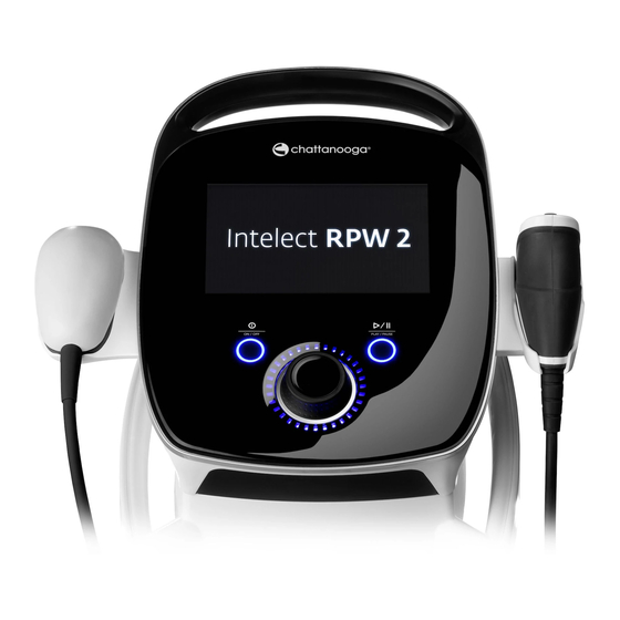
Summary of Contents for Chattanooga Intelect RPW 2
- Page 1 RPW 2 Intelect ® User Manual Operator and Installation Instructions INTELECT RADIAL PRESSURE WAVE 2 (RPW 2 ) REF 2 1 7 5 KIT (1 0 0 V) REF 2 1 7 3 KIT (1 2 0 V) REF 2 1 7 4 KIT (2 3 0 V)
-
Page 2: Table Of Contents
CONTENTS INTRODUCTION GENERAL WARNINGS AND PRECAUTIONS FOREWORD CAUTION INTENDED USER PROFILE WARNING INTENDED ENVIRONMENT FOR USE DANGER INTENDED USE PRECAUTIONARY INSTRUCTIONS SETUP INSTRUCTIONS HOME SCREEN DESCRIPTIONS UNPACKING THE DEVICE DESCRIPTION OF DEVICE MARKINGS DEVICE DESCRIPTION PAIN IN THE MUSCULOSKELETAL SYSTEM FALCON HANDPIECE SET UP POWERING UP THE DEVICE INDICATIONS FOR USE... - Page 3 CONTENTS V-ACTOR HF HANDPIECE CHANNEL STATUS POSSIBILITES OPERATIONS, SET-UP, CLEANING BAR EXPLAINED AND MAINTENANCE COMFORT MODE EXPLAINED DEVICE DESCRIPTION SETTINGS INSTALLATION INSTRUCTIONS HOME SCREEN UNPACKING TREATMENT REVIEW SCREEN SCOPE OF SUPPLY GUIDELINES SCREEN CONNECTING THE HANDPIECE RADIAL PRESSURE WAVE OPERATION OPERATION SINGLE SHOT MODE START-UP...
- Page 4 SYMBOLS AND LABELS SERVICE LIFE WARRANTY AND SERVICE WARRANTY REPAIR/OUT OF WARRANTY REPAIR WARRANTY DEVICE MAINTENANCE APPENDIX WATER RESERVOIR CLEANING THE INTELECT RPW 2 ELECTROMAGNETIC COMPATIBILITY (EMC) COPY OF MANUAL INSTRUCTION FOR SOFTWARE UPGRADE DEVICE MAINTENANCE FALCON HANDPIECE CLEANING, MAINTENANCE; OVERHAUL CLEANING...
-
Page 5: Introduction
Consult The Intelect RPW 2 device is intended to be used as a other resources for additional information regarding the therapeutic modality by clinicians needing to provide application of Radial Pressure Wave and Vibration therapies. -
Page 6: Home Screen Descriptions
INTRODUCTION HOME SCREEN ICON DESCRIPTIONS DESCRIPTION OF DEVICE MARKINGS Falcon Radial Pressure Waves Refer to Instructional Manual and handpiece Quick Start Guide Booklet Vibration Therapy handpiece V-Actor Warning, Caution, or Danger Shortcut Electrical type B equipment SPS (Suggested Parameter Setup) Play Custom Protocols Pause... - Page 7 INTRODUCTION Relative Humidity Range Atmospheric Pressure Range Testing agency CE Mark of Conformity with notified body number Class 1 equipment Radio frequency equipment WEEE Directive conformity Shelf life Batch number No condensation allowed Read the instruction for use AC Rated supply voltage Markings are conform to ISO7010 and ISO15-223-1"...
-
Page 8: Pain In The Musculoskeletal System
INTRODUCTION PAIN IN THE MUSCULOSKELETAL SYSTEM Tibial Edge Syndrome Pain located along or just behind the medial edge of the Before a treatment with Radial Pressure Wave, a correct tibia examination and diagnosis should be performed. Proximal Iliotibial band Friction Syndrome/Trochanteric Insertion Tendonitis Please stay current with the latest developments and Pain or aching on the outer side of the knee or hip... -
Page 9: Indications For Use
INDICATIONS FOR USE CONTRAINDICATIONS The Intelect RPW 2 should NOT be used under the ® following conditions: • Brain or spinal column in the treatment area. • On any body part during pregnancy. • Direct application over cancerous tumors or lesions due to its potential to increase blood flow to the area of malignancy. -
Page 10: Additional Precautions
INDICATIONS FOR USE ADDITIONAL PRECAUTIONS ADVERSE EFFECTS When administering Radial Pressure Wave treatment, keep Side effects could occur after a treatment with Radial in mind the following: Pressure Wave therapy. The majority will appear after 1-2 • Radial Pressure Wave treatment should be applied days. -
Page 11: Device Desciption
DEVICE DESCRIPTION PRODUCT DESCRIPTION The Intelect RPW 2 is a compressed air-operated ballistic ® shock wave generator. The shock waves in the device are generated with a precision ballistic mechanism in the handpiece. A projectile is accelerated by compressed air. The motion and weight of the projectile produce kinetic energy. -
Page 12: Components
DEVICE DESCRIPTION COMPONENTS Gel Bottle Throughout these instructions the terms “left” and “right” referring to the device sides are from the perspective of a user standing in front of the device. The components of the Intelect RPW 2 are shown below. ®... -
Page 13: Ifu Download
DEVICE DESCRIPTION IFU DOWNLOAD TO STOP TREATMENT 1. To download the IFU go to the Chattanooga website Press Play/Pause button to pause treatment then press Stop www.chattanoogarehab.com on touch screen. If device is on mains power press the On/Off 2. Complete the registration to be informed of software and... -
Page 14: General Warnings And
• Use of parts or materials other than DJO’s can degrade minimum safety. • Connect to this device only items and equipment that have been specified in this IFU as part of the Intelect RPW 2 System or that have been specified as being compatible with the Intelect RPW 2 System. -
Page 15: Warning
• Contaminated transmitters, and gel can lead to infection. Disinfect the handpiece after each treatment. • DO NOT use the Intelect RPW 2 in water (Bath, Shower, etc.) that could cause electronic failure • DO NOT operate the Intelect RPW 2 within the vicinity or environment of any microwave and RF shortwave diathermy system. -
Page 16: Danger
GENERAL WARNINGS AND PRECAUTIONS DANGER • DO NOT connect the device to an electrical supply without first verifying that the power supply is the correct voltage. Incorrect voltage may cause device damage, malfunction, electrical shock, fire, or personal injury. Your device was constructed to operate only on the electrical voltage specified on the Voltage Rating and Serial Number Plate. -
Page 17: Setup Instructions
SETUP INSTRUCTIONS UNPACKING THE DEVICE 4. Retain the original packaging. It may prove useful for any equipment transport. Please refer to chapter to page 64, The device is generally delivered with the packaging the Accessories Section for information. For information on material supplied by the manufacturer. - Page 18 SETUP INSTRUCTIONS 6. The Gel Holder cup can be attached on the any side of the device 7. The cable holder is used to hang the handpieces cables Throughout these instructions the terms “left” and“right” referring to the machine sides are from the perspective of a user standing in front of the device.
-
Page 19: Device Description
DEVICE DESCRIPTION DEVICE DESCRIPTION Handle Color Touch Screen Power Button Play / pause button V actor applicator support Rotary adjustment Falcon Hand Piece Support knob Switch USB Connector ON/OFF Transmitter Tray Holder* * Device delivered with 2 transmitters. Other transmitters displayed are optional. * V-actor applicator is optional. -
Page 20: Falcon Handpiece Set Up
SETUP INSTRUCTIONS FALCON HANDPIECE SET UP 3. Screw the shaft into the handpiece until finger-tight. Using one hand, press the handpiece firmly onto the table 1. Unscrew the shaft from the handpiece and pull it out of and tighten the shaft using the open-end spanner. It must the handpiece handle. -
Page 21: Powering Up The Device
SETUP INSTRUCTIONS 2. The first setup screen will be displayed after this allowing the user to set language and time in the device. 3. If after this step you see the screen below, switch of the device and follow instructions in point 4 below. If POWERING UP THE DEVICE you do not see this screen the device is ready to use. -
Page 22: System
SYSTEM OPERATING DATA AND RATINGS FALCON HANDPIECE TECHNICAL SPECIFICATIONS Values displayed on the device are with a tolerance of ±10% Width....................420 mm Compressed air input............1.0 - 5.0 bar Depth ....................410 mm Ambient temperature during operation......10 - 40 °C Height ....................1140 mm Ambient temperature during storage......0 - 60 °C Standard Weight (with one handset).......32 Kg (72 lbs) and transport... -
Page 23: Patient Preparation
PATIENT PREPARATION PATIENT PREPARATION Before applying Radial Pressure Wave therapy to the patient, first prepare the patient’s skin. By properly preparing the patient’s skin for therapy, it allows more energy to reach the targeted areas and reduces the risk of skin irritation. To prepare the patient’s skin for therapy, do the following: 1. -
Page 24: User Interface
USER INTERFACE DEVICE USER INTERFACE Intelect RPW 2 ON/OFF button has several light indicators: ® - steady ON from device connection to the mains - Flashing while powering ON/OFF PLAY/PAUSE button blue indicator: it flashes when user can start/resume a treatment. Otherwise, steady. SCREEN DESCRIPTION 1. - Page 25 USER INTERFACE Each screen contains the following areas: Menu Bar Located at the top of each screen and lists the current screen name. Settings Main area Located under the menu bar, this area displays icons unique to the current screen. 1.
-
Page 26: Understanding Your Bottom Banner
USER INTERFACE UNDERSTANDING YOUR BOTTOM BANNER The home screen will tell you if the handpiece(s) is connected (available = connected; unavailable = not connected). If the handpiece is connected but the device detects an error, a message might be displayed, please see page 64 for details. The left side of the screen will tell you what transmitter you have selected with an image of the transmitter - ensure you have the proper transmitter on the end of the handpiece. -
Page 27: Channel Status Possibilites
USER INTERFACE CHANNEL STATUS POSSIBILITIES: Indicates the Indicates that handpiece is handpiece is not available for use available for use Indicates that Indicates that transmitter transmitter type has type is selected not been selected Indicates Indicates treatment is compressor is running armed Indicates that the handpiece... -
Page 28: Comfort Mode Explained
A low level of Bar energy would not be efficient, as 50% of the energy is lost at the skin’s surface. While a high level of energy could generate intense pain during the treatment causing the patient to not seek further therapies. The Intelect RPW 2 comfort mode is designed to help the clinician determine what level of Bar energy and discomfort the patient can accept. -
Page 29: Settings
USER INTERFACE SETTINGS The settings icon on the home screen menu bar (see first page of User Interface section) offers users the opportunity to set preferences: 1. Home screen name: on the home screen, the "current screen name" displayed in the middle portion of the menu bar is by default ‘Home’. -
Page 30: Home Screen
USER INTERFACE HOME SCREEN The Intelect RPW 2 Home screen provides access to all of the system modalities and functions. The Home screen has the ® following information: Modalities Assign or launch Shortcut Libraries « Suggested Parameter Setup » Pre-programmed protocol library Clinician protocol library Educational library: ·... -
Page 31: Treatment Review Screen
USER INTERFACE TREATMENT REVIEW SCREEN By selecting Radial Pressure Wave, Vibration Therapy, or the screen will automatically change to the ‘treatment review screen. The Intelect RPW 2 Treatment Review screens include the following information: ® Parameters Swipe vertically to see more parameters Save/Overwrite default settings or... - Page 32 USER INTERFACE Select transmitter INTELECT RPW 2 USER MANUAL ®...
-
Page 33: Guidelines Screen
USER INTERFACE GUIDELINES SCREEN The Guidelines provide the following information: Modality description, terms, indications and contraindications, treatment guidelines Touch image to view in full screen mode Swipe horizontally for more RADIAL PRESSURE WAVE OPERATION Complete the following steps to begin treatment: 1. - Page 34 USER INTERFACE 3. SET UP TREATMENT On the treatment review screen - you can adjust treatment parameters to desired level. Note: Never start with pressure adjustment – first adjust all other parameters and set Bar just before starting treatment Parameters 1.
- Page 35 USER INTERFACE 5. START TREATMENT WITH COMFORT MODE "ON" Press the start/pause button The compressor is arming for a few second then when the message "armed" is displayed, the treatment can start by triggering the handpiece. The button on the top of the handpiece is the trigger button, also called the start/stop button. INTELECT RPW 2 USER MANUAL ®...
- Page 36 USER INTERFACE 6. TREATMENT RUNNING When the treatment starts with Comfort mode "ON" the bar will increase progressively starting at 1/10 of the set value. The actual value is displayed on the Comfort mode progression bar. When the patient states that the treatment feels uncomfortable or painful, the therapist pauses the treatment by triggering the handpiece.
- Page 37 USER INTERFACE 7. PAUSE TREATMENT Pausing treatment will automatically display stop treatment on the Treatment Review screen. The treatment can be paused by pressing the PAUSE buttons located on the device. The treatment can also be paused by pressing the button located on the handpiece. Please reference the example scenarios: Scenario 1: handpiece is active and projectile is moving.
-
Page 38: Single Shot Mode
USER INTERFACE 8. STOP TREATMENT If handpiece is active and projectile is moving: Pause the treatment first, then the handpiece becomes inactive. Then by selecting Stop treatment, the treatment will end and treatment summery displayed. 9. SINGLE SHOT MODE The Falcon D-Actor has the ability to do single shots. This can be done by selecting Frequency and turning the dial to the left so that the Hz is displayed as “—“. - Page 39 USER INTERFACE 10. TREATMENT SUMMARY When treatment has completed, the Treatment Summary screen will appear with the following options: • Repeat the treatment by pressing the Run again box. • Save » therapy information to Treatment Data » the treatment protocol to the Custom Protocols •...
-
Page 40: Sps (Suggested Parameter Setup)
USER INTERFACE SPS (SUGGESTED PARAMETER SETUP) The Intelect RPW 2 has a Suggested Parameter Setup (SPS) icon that is a series of protocol presets where the body area, clinical ® indication, pathological condition and severity are selected by the user, and the suggested algorithm will select the parameter settings. - Page 41 USER INTERFACE 3. Select INDICATION Select Pressure Wave 4. Select INDICATION Select Pain Zone treatment INTELECT RPW 2 USER MANUAL ®...
- Page 42 USER INTERFACE 5. SELECT MODALITY Select Radial Pressure Wave 6. SET UP TREATMENT On the treatment review screen the suggested treatment settings are displayed and you can adjust parameters to desired level. Parameters 1. Touch to activate 2. Adjust with Adjustment dial: •...
- Page 43 USER INTERFACE 7. START TREATMENT Press the START button Treatment Running INTELECT RPW 2 USER MANUAL ®...
-
Page 44: Treatment Data
USER INTERFACE TREATMENT DATA After a treatment has been completed, Treatment data can be saved on the Intelect RPW 2 for later use on the device. ® SAVE TREATMENT DATA 1. Touch ASSIGN TO on the Treatment Summary screen 2. Select ASSIGN TO to save Treatment Data INTELECT RPW 2 USER MANUAL ®... - Page 45 USER INTERFACE 3. The TREATMENT DATA screen appears Save treatment data by selecting ADD Create & save to new ID Select & save to existing ID SAVE TREATMENT DATA TO A NEW ID: Enter ID and Save INTELECT RPW 2 USER MANUAL ®...
- Page 46 USER INTERFACE VIEW AND MANAGE TREATMENT DATA Press the TREATMENT DATA ICON on the home screen 1. VIEW Treatment Data Select Treatment Data INTELECT RPW 2 USER MANUAL ®...
- Page 47 USER INTERFACE The TREATMENT HISTORY is displayed including all previously saved treatment sessions ranked chronologically Select session to view Treatment Summary for that session. Session details are displayed INTELECT RPW 2 USER MANUAL ®...
- Page 48 USER INTERFACE 2. DELETE Treatment Data Delete all IDs Delete one ID INTELECT RPW 2 USER MANUAL ®...
- Page 49 USER INTERFACE Confirm or cancel Delete all treatment sessions INTELECT RPW 2 USER MANUAL ®...
- Page 50 USER INTERFACE Delete one session INTELECT RPW 2 USER MANUAL ®...
-
Page 51: Custom Protocols
USER INTERFACE CUSTOM PROTOCOLS The Intelect RPW 2 allows for a maximum of 25 custom protocols to be defined. ® SAVE A CUSTOMIZED PROTOCOL A new custom protocol may be saved at either the Treatment Review or Treatment Summary screen. 1. - Page 52 USER INTERFACE 3. The Custom Protocol library is displayed where you can save the protocol as NEW custom protocol or OVERWRITE an existing custom protocol Create new custom protocol Select and overwrite existing protocol Alphabetical list Swipe to see more CREATE NEW CUSTOM PROTOCOL: Enter Custom Protocol Name and Save INTELECT...
- Page 53 USER INTERFACE VIEW AND MANAGE CUSTOM PROTOCOLS Touch the CUSTOM PROTOCOLS icon on the Home Screen 1. VIEW Custom Protocol Select desired Custom Protocol INTELECT RPW 2 USER MANUAL ®...
- Page 54 USER INTERFACE The TREATMENT REVIEW SCREEN is displayed showing the protocol settings. Start treatment or perform other actions. 2. DELETE custom protocol Delete all protocols INTELECT RPW 2 USER MANUAL ®...
- Page 55 USER INTERFACE Delete one protocol INTELECT RPW 2 USER MANUAL ®...
-
Page 56: Shortcuts
USER INTERFACE SHORT CUTS Intelect RPW 2 allows for 12 custom protocol shortcut assignments on the home screen. ® ASSIGN SHORTCUT Complete the following steps to assign a home screen shortcut unassigned. Short cut icons appear grey in color for a customized protocol: Press one of the unassigned “Shortcut”... - Page 57 USER INTERFACE Shortcut assigned on home screen Once assigned the shortcut icon becomes the color associated with the modality it contains INTELECT RPW 2 USER MANUAL ®...
-
Page 58: Unassign Shortcut
USER INTERFACE UNASSIGN SHORT CUT Complete the following steps to unassign a Home screen shortcut for a customized protocol: From the Home screen, press and hold the shortcut icon you wish to unassign. The device will display a text box asking, “Remove “My Custom Protocol 1” shortcut?” Select “No”... -
Page 59: Clinical Resources
USER INTERFACE CLINICAL RESOURCES The Intelect RPW 2 contains a unique Clinical Resources Library. ® The anatomical and pathological image library are designed to aid the operator in visually understanding and locating specific muscle groups and commonly found problems associated with pathological conditions, as well as providing an educational tool for the clinician to use with the patient. - Page 60 USER INTERFACE 2. Touch the body part for which you wish to view information. Choose either anterior (on left of screen) or posterior (on right of screen). 3. The available images for the selected body part are displayed. Touch the image you want to see in full screen mode. INTELECT RPW 2 USER MANUAL ®...
- Page 61 USER INTERFACE 4. Full screen image Close full screen mode INTELECT RPW 2 USER MANUAL ®...
-
Page 62: Modality Descriptions
USB drive. 3. In the setting menu eject the USB drive to enable safe removal from the Intelect RPW 2 device. 4. The format of the file is a bitmap file and it is date & time coded in the file name. -
Page 63: Troubleshooting Codes
TROUBLESHOOTING TROUBLESHOOTING CODES 1. All system messages, warning messages and fault messages that are generated by the device are self-explanatory excepting system error. 2. If System error occurs, note error code and contact DJO selling dealer or DJO Service Department 3. -
Page 64: Accessories
ACCESSORIES ACCESSORIES REPLACEMENT ACCESSORIES The following tables provide users of the Intelect RPW 2 the necessary information to order replacement accessories used ® with the system. This list of replacement accessories is designed for use with the Intelect RPW 2 . When ordering, provide ®... -
Page 65: Optional Accessories
20mm Transmitter ® 28736 D20-T Transmitter 29725 D35-S, 35 mm, D-Actor Transmitter, Black ® 29539 ATLAS Transmitter 28946 INTELECT RPW 2 SPINE-ACTOR Transmitter set 28945 INTELECT RPW 2 PERI-ACTOR Transmitter set 19365 V-Actor ® 28740 V-Actor V25 Transmitter ® 28741... -
Page 66: V-Actor Hf Handpiece Operations, Set-Up, Cleaning And Maintenance
The preconditions for using the V-ACTOR HF handpiece correspond to the preconditions for operating the Note: The V10 vibration transmitter is an optional accessory for the Intelect RPW 2. Please read the Contraindications V-Actor HF and must be ordered separately. chapter in this IFU for more details. -
Page 67: Connecting The Handpiece
• Insert the plug of the handpiece into the handpiece connector on the Intelect RPW 2. • Make sure that the red dot on the plug is aligned with the red dot on the handpiece connector. -
Page 68: Operation
Before starting treatment, it is essential to perform the FUNCTIONAL CHECKS described below. START-UP • Connect the V-ACTOR HF handpiece to the Intelect RPW 2. ® • Set the pulse energy in V-ACTOR HF operating mode to an initial value of 2 bar. - Page 69 V-ACTOR HF HANDPIECE OPERATIONS, SET-UP, CLEANING, AND MAINTENANCE The chart shown here displays the relationship between pressure and frequency when using the V-Actor HF with the Intelect RPW 2. ® Pressure (Bar) Frequency (Hz) INTELECT RPW 2 USER MANUAL ®...
-
Page 70: Treatment
V-ACTOR HF HANDPIECE OPERATIONS, SET-UP, CLEANING, AND MAINTENANCE TREATMENT SAFETY INFORMATION Before using the device, the user must make sure it is functioning safely and in proper condition. Each time the device is transported, subsequently make sure that all functional checks have been performed on the device before you start treatment. -
Page 71: Cleaning, Maintenance, Overhaul
V-ACTOR HF HANDPIECE OPERATIONS, SET-UP, CLEANING, AND MAINTENANCE CLEANING, MAINTENANCE, OVERHAUL • To remove the V40 vibration transmitter, unscrew the vibration transmitter from the handpiece. • Unscrew the vibration transmitter screw cap (1 and 5) and pull out the shock transmitter. CHANGING THE VIBRATION •... -
Page 72: Handpiece
V-ACTOR HF HANDPIECE OPERATIONS, SET-UP, CLEANING, AND MAINTENANCE HANDPIECE Cau tio n! Cleaning agents and disinfectants may generate an explosive atmosphere. Disconnect the handpiece from the control device before starting any cleaning or maintenance work. Attentio n! It is essential that no fluid be permitted to penetrate either the device or its tubing. •... -
Page 73: V25 And V10
V-ACTOR HF HANDPIECE OPERATIONS, SET-UP, CLEANING, AND MAINTENANCE REPROCESSING THE HANDPIECE AND VIBRATION TRANSMITTERS After each use, the parts of the handpiece that come into contact with the patient must be cleaned and disinfected thoroughly before they are used again. The instructions must be strictly observed in order to prevent damage to the parts and malfunctions. -
Page 74: Trouble-Shooting
V-ACTOR HF HANDPIECE OPERATIONS, SET-UP, CLEANING, AND MAINTENANCE TROUBLE-SHOOTING Fault description Possible cause Corrective actions Check the cable and tube connections and replace them, if No compressed air supply Leaks in handpiece cable or cable not properly connected necessary No power output Handpiece defective Replace the handpiece ACCESSORIES AND SPARE PARTS... -
Page 75: Symbols And Labels
V-ACTOR HF HANDPIECE OPERATIONS, SET-UP, CLEANING, AND MAINTENANCE SYMBOLS AND LABELS Label Meaning You must read the operating manual! WARRANTY AND SERVICE WARRANTY FOR THE V-ACTOR HF HANDPIECE ® The V-ACTOR HF handpiece is a wear part. We will replace new handpieces that have performed up to 1 million pulses at ®... -
Page 76: Device Maintenance
COPY OF MANUAL To reattach the reservoir To obtain a copy of the Intelect RPW 2 User Manual, contact 1. Replace the reservoir lid and insert the water tube into the your local representative or DJO Global Customer Care ®... -
Page 77: Falcon Handpiece Cleaning, Maintenance; Overhaul
FALCON HANDPIECE CLEANING, MAINTENANCE; OVERHAUL FALCON HANDPIECE CLEANING, MAINTENANCE; OVERHAUL ® CLEANING Regular cleaning ensures perfect hygiene and operation of the Falcon handpiece. The handpiece, in particular the shock ® transmitter, must be thoroughly cleaned and disinfected after each therapy session. Cautio n! Flammable and volatile cleaning and disinfecting agents may generate an explosive atmosphere. -
Page 78: Standard Shock Transmitters
CLEANING, MAINTENANCE, OVERHAUL STANDARD SHOCK TRANSMITTERS 5. Screw the shock transmitter screw cap onto the handpiece until finger-tight. 1. Disconnect the handpiece from the control device. 2. Unscrew the shock transmitter screw cap from the handpiece. 6. After replacing the shock transmitter, make sure that the handpiece cap and the cap parts are screwed firmly in place. -
Page 79: Spine And Fasciae Shock Transmitters
CLEANING, MAINTENANCE, OVERHAUL SPINE AND FASCIAE SHOCK 4. Push the inner part of the clutch in direction to the shaft of the handpiece (1). TRANSMITTERS • Push the shock transmitter into the clutch (2). 1. Disconnect the handpiece from the control device. The spine or fasciae transmitter set contents a special clutch for mounting the spine or fasciae transmitters. -
Page 80: Cleaning The Handpiece
CLEANING, MAINTENANCE, OVERHAUL CLEANING THE HANDPIECE 4. Unscrew the shaft from the handpiece and pull it out of the handpiece handle (5). Note: After cleaning, the handpiece must be dry before it can be • Use the supplied open-end spanner (4) for this reassembled. -
Page 81: Cleaning The Shock Transmitters
CLEANING, MAINTENANCE, OVERHAUL CLEANING THE SHOCK TRANSMITTERS Note: The shock transmitter insert of two-part transmitter caps can only be dismantled and the sealing rings can only be removed using special tools. You should avoid doing this because it could result in damage to the shock transmitter. -
Page 82: Spine And Fasciae Shock Transmitters
CLEANING, MAINTENANCE, OVERHAUL SPINE AND FASCIAE SHOCK • After shockwave application for humans an ultrasonic bath of our shockwave transmitters can TRANSMITTERS have an additional cleaning effect. However, an • Remove the applicator from the handpiece and ultrasonic bath is not a requirement. disconnect it from the coupling. -
Page 83: Overhaul
CLEANING, MAINTENANCE, OVERHAUL OVERHAUL Shock waves are generated mechanically. Due to the effects of friction, the handpiece components are continuously exposed to mechanical stress, which will cause minor wear. Note: The Falcon handpiece should be overhauled about every 1,000,000 shocks. This can be done by the user of the device. All that is required is the overhaul kit, which includes all required wear parts. - Page 84 CLEANING, MAINTENANCE, OVERHAUL 1. Disconnect the handpiece from the control device. 3. Pull the tightly fitting guide tube out of the shaft. If necessary, use a thin metal rod or the supplied hexagonal • Unscrew the shock transmitter screw cap spanner as a pulling tool by inserting it through the respectively the clutch for the spine and fasciae openings in the guide tube.
- Page 85 CLEANING, MAINTENANCE, OVERHAUL 5. Dispose of the used guide tube and the used projectile 7. Clean the shaft, the shock transmitter (including firmly seated sealing rings) and the shock transmitter screw cap using a disinfectant containing alcohol. These are reused after cleaning.
- Page 86 CLEANING, MAINTENANCE, OVERHAUL 11. Insert the new projectile into the fitted guide tube. 9. Take out the new guide tube and the new projectile from the overhaul kit. 12. Screw the shaft into the handpiece until finger-tight. 10. Insert the guide tube into the opening in the shaft by •...
- Page 87 SERVICE AND WARRANTY SERVICE LIFE OF THE FALCON ® HANDPIECE The Falcon handpiece should be overhauled after around every 1 million shocks. Provided this interval is observed, the average expected service life is approx. • 5 million shocks for the handpiece •...
-
Page 88: Service & Warranty
When disposing of this medical product, no special measures have to be observed. Please proceed in accordance with applicable country specific regulations. After expiration of its service life, dispose of the Intelect RPW 2 as waste electronic equipment. INTELECT RPW 2 USER MANUAL ®... -
Page 89: Warranty
SERVICE AND WARRANTY WARRANTY COMPANY SHALL NOT BE LIABLE IN ANY EVENT FOR INCIDENTAL OR CONSEQUENTIAL DAMAGES. Attention Modifications to the device or handpiece are not permitted. This warranty gives you specific legal rights and you Any unauthorized opening, repair or modification of may also have other rights which vary from location to the device by unauthorized personnel will relieve the location. -
Page 90: Appendix
APPENDIX ELECTROMAGNETIC COMPATIBILITY Compatibility of Medical Devices for Clinical/Biomedical Engineers. AAMI TIR 18-1997. Arlington, Virginia: Association (EMC) for the Advancement of Medical Instrumentation; 1997. The Intelect RPW 2 has been tested and found to comply ® Caution: with the electromagnetic compatibility (EMC) limits Medical electrical equipment requires special precautions for medical devices to IEC 60601-1-2. - Page 91 The Intelect RPW 2 should not be used adjacent to or stacked with other equipment. If adjacent or stacked use is necessary, Intelect RPW 2 should be observed to verify normal operation in the configuration in which it will be used.
- Page 92 12.1 Electromagnetic emissions: Guidance and Manufacturer’s Declaration – Electromagnetic Emissions Intelect RPW 2 is intended for use in the electromagnetic environment specified below. It is the responsibility of the customer or user to ensure that the Intelect RPW 2 device is used in such an environment.
- Page 93 To assess the electromagnetic environment due to fixed RF transmitters, an electromagnetic site survey should be considered. If the measured field strength in the location in which the Intelect RPW 2 exceeds the applicable RF compliance level above, the Intelect RPW 2 device should be observed to verify normal operation. If abnormal performance is observed, additional measures may be necessary, such as reorienting or relocating the Intelect RPW 2 device.
- Page 94 Portable RF communications equipment (including peripherals such as antenna cables and external antennas) should be used no closer than 30 cm (12 inches) to any part of the Intelect RPW 2, including cables specified by the manufacturer. Otherwise, degradation of the performance of this equipment could result.
- Page 95 DJO France SAS Centre Européen de Frêt 3 rue de Bethar 64990 Mouguerre • France T: + 33 (0) 5 59 52 86 90 • F: + 33 (0) 5 59 52 86 91 DJOglobal.com DJO, LLC | 2900 Lake Vista Drive | Dallas, TX 75067 | U.S.A. www.DJOglobal.com Copyright ©...
Need help?
Do you have a question about the Intelect RPW 2 and is the answer not in the manual?
Questions and answers