Table of Contents
Advertisement
Quick Links
Advertisement
Table of Contents

Related Manuals for Chattanooga Intelect Focus Shockwave


Summary of Contents for Chattanooga Intelect Focus Shockwave
- Page 1 Focus Shockwave Operating Manual...
-
Page 2: Table Of Contents
Contents Introduction..............General Safety Information . - Page 3 Setting treatment parameters ..........F-SW energy display task .
- Page 4 Conformity with directives ..........Conformity with standards .
-
Page 5: Introduction
Introduction This operating manual contains certain types of text design intended to assist you in comprehending the significance of the text based on its appearance. Instructions for actions • This text instructs you in how to operate your device correctly. •... - Page 6 CAUTION The source of the danger is stated here. These are the possible consequences! ► The instructions for avoiding the danger are given here. NOTICE indicates that incorrect operation could lead to damage to the device. NOTICE The source of the danger is stated here. These are possible consequences! ►...
- Page 7 Symbol Notification Manufacturer CE mark Device serial number CSA certification mark It is essential to comply with the operat- ing manual Fuse Electromagnetic interference may occur in the vicinity of devices marked with this symbol. Hot surface Explosion Electrical warning sign: high voltage 13 610 0002 11.2022...
-
Page 8: General Safety Information
Incorrect handling of the device Possibility of injuries to the patient and the operating personnel! ► Read this chapter carefully before you start using the Chattanooga Intelect F-SW. ► Read the separate operating manuals for all devices associated with the Chatta- nooga Intelect F-SW. - Page 9 • Disconnect the Chattanooga Intelect F-SW from the mains plug before starting any cleaning or maintenance work. • Disconnect the connected handpieces from the device before carrying out clean- ing and maintenance work. Do not reconnect it until everything has been com- pletely reassembled.
-
Page 10: Safety During Treatment Of The Patient
The following agents are NOT to be used during operation: – Highly inflammable and potentially explosive inhalation anaesthetics and mixtures of the same, such as • Ether pro narcosi (diethyl ether) • Cyclopropane. – Inflammable, highly volatile skin cleaning agents and skin disinfectants which can form a potentially explosive atmosphere, such as •... - Page 11 Please read Chapter 9.3.1 EMC GUIDELINES AND MANUFACTURER S DECLARATION If the Chattanooga Intelect F-SW is connected to a 240 V mains supply with a mains frequency of 60 Hz, the mains supply must be balanced. Setup and operation There are ventilation slits on the device which must not be covered by other objects.
-
Page 12: Manufacturer`s Responsibility
WARNING No modifications are to be made to this device without the permission of the manu- facturer. The manufacturer of the Chattanooga Intelect F-SW is only responsible for the impact of its product on safety, reliability and performance if: –... -
Page 13: Principles
A sound knowledge of trigger point therapy and trigger point shock wave therapy (TrST) is required for therapeutic application of the Chattanooga Intelect F-SW in the field of trigger point shock wave thera- Qualified training in acupuncture and acupuncture shock wave therapy (AkuST) is required for therapeu- tic application of the Chattanooga Intelect F-SW in the field of acupuncture. -
Page 14: Contraindications
Dermatology Wound healing – Ulcers • Arterial ulcers • Venous ulcers • Diabetic foot • Pressure sores, Decubital ulcers – Burns – Acute and chronic lesions – Post-traumatic necrosis – Wounds with disturbed healing – Postsurgical wounds – Traumatic wounds Cellulite / lipedema / lymphedema Urology –... -
Page 15: Side Effects
After treatment with the Chattanooga Intelect F-SW side effects may occur. ► Familiarise yourself with the list of side effects. ► Inform the patient of possible side effects. Treatment with the Chattanooga Intelect F-SW may cause the following side effects: – Swelling, reddening, haematomas –... -
Page 16: Training Of The Operator
2.2.2 Training of the operator Operators of the Chattanooga Intelect F-SW must have been adequately trained in us- ing this device. An introduction to the principles of operation will be provided by your dealer with reference to this operating manual and will be documented in the system logbook. -
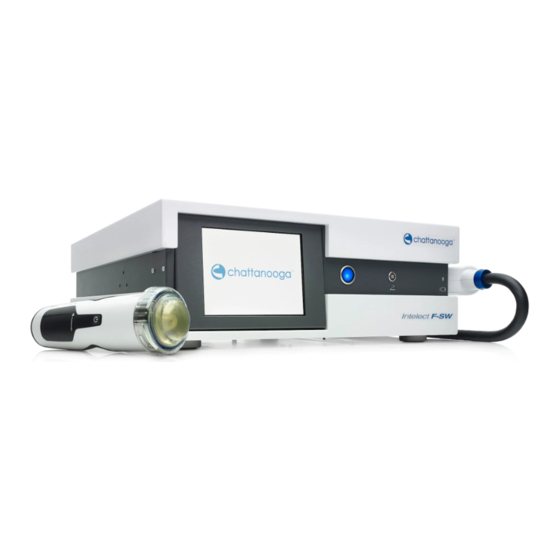
Page 17: System Description
System description Control and functional elements Fig. 3-1 Front view of Chattanooga Intelect F-SW Monitor Power indicator Connection for foot switch F-SW handpiece connection 13 610 0002 11.2022... - Page 18 Fig. 3-2 Rear view of Chattanooga Intelect F-SW Potential equalisation connection not used Mains connection Mains fuse holder Mains switch USB connection for USB stick, USB mouse, USB keyboard Water supply connection not used Type Plate 13 610 0002 11.2022...
-
Page 19: F-Sw Handpiece And Optional C-Actor Handpiece
F-SW handpiece and optional C-ACTOR handpiece Focused shock waves with a short wavelength that are concentrated on a focal zone outside the handpiece are administered over the F-SW handpiece or the C-ACTOR handpiece into the body at the treatment zone that has been established by diagnosis. Optical difference between F-SW and C-ACTOR : The F-SW has a blue ring around the coupling diaphragm and the C-ACTOR has a red ring around the coupling dia- phragm. - Page 20 Fig. 3-5 Depth of therapeutical effect of F-SW handpiece Fig. 3-6 Depth of therapeutical effect of C-ACTOR handpiece Perform changing of the stand-off devices as described in chapter 6.2.1 C • HANGING THE STAND OFF DEVICE The stand-off has a limited service life. It should be replaced if there are visible changes in the material (discolouration, tarnishing, streaks, gas bubbles), deformation of the surface in the coupling area or leaks.
-
Page 21: Installation Instructions
Installation Instructions Scope of Supply The standard scope of supply of the Chattanooga Intelect F-SW includes the following items: – Chattanooga Intelect F-SW control device – F-SW SEPIA LT handpiece – Handpiece holder – Mains cables – Gel bottle –... -
Page 22: Installing The Handpiece Holder
• Use a 2.5 mm Allen key for installation • Screw the handpiece holder onto the right side wall of the Chattanooga Intelect F-SW, as shown in the picture below. Fig. 4-1 Mounted handpiece holder Handpiece holder mounted to right side wall... -
Page 23: Connecting The Electrical Power Supply
Connecting the electrical power supply DANGER Improper connection: There is a risk of electric shock! ► Do not connect the device to a power supply network unless it has a protective conductor. ► Never use multi-socket power strips. Connect the mains cable to the mains connector on the rear of the device (see F •... -
Page 24: Connecting Handpiece
The locking screw must be tightened up to the stop until finger-tight. Fig. 4-4 Connecting the F-SW handpiece Fill the water circuit of the Chattanooga Intelect F-SW first when the F-SW handpiece is first connected after delivery. The instrument will signal “water level too low” when it is switched on. -
Page 25: Transport
• Set the device slantly down in order to avoid squeezing the fingers. 4.12 Compatibility The Chattanooga Intelect F-SW is allowed to be operated with the following accesso- ries: Handpiece F-SW SEPIA LT Art no. 19000 Handpiece C-ACTOR SEPIA LT Art. -
Page 26: Operation
Operation The Chattanooga Intelect F-SW is operated using a colour TFT LCD monitor with touch screen function and a graphical user interface. Graphical user interface The user interface of the Chattanooga Intelect F-SW is divided into various areas for displaying different information. The individual controls are arranged in function groups (see picture below): Fig. - Page 27 Parameter entry screen Open the sub-menu Jump to the L sub-menu (call up saved ONFIGURATION OAD CONFIGURATION parameter configurations or patient records) Main and sub-menu Step back Return to parameter entry screen ENU EXIT Delete configurations ELETE Save configurations Confirm entries, acknowledge messages The arrow keys can be used for changing (increasing or decreasing) the parameter values.
- Page 28 Selection area The selection area (see picture below) of the parameter entry screen contains the nom- inal value selection fields “Energy level”, “Number of shocks” and “Frequency” Fig. 5-2 Parameter entry screen – When you open a menu, the name of the opened menu appears in the top line against a dark blue background.
-
Page 29: Function Overview
Function overview Main menu 1st sub menu 2nd sub menu Actual val. reset Info English Save configuration Language German Load configuration Time Spanish Setup Touch-screen calibration Italian Warnings Drain water French Data transfer Fill water Portuguese Exit user interface Bleed water circuit Russian Reset water change time Polish... - Page 30 1st sub-menu Info – Total shock count and instrument operating hours (depending on operating mode selected) – Total number of shocks of the respective handpiece, data on monitoring software, operating system, hard- ware serial numbers and modification status – Information about modules: To view serial numbers and indexes of the modules, scroll to the second page of the Info window by using the arrow key.
-
Page 31: Starting The Instrument
A detailed description can be found in Chapter 6.3.2 F ILLING THE WATER CIRCUIT Warm-up phase Once a day, the Chattanooga Intelect F-SW starts a warm-up phase lasting about 3 minutes, the progress of which is shown in the progress indicator. The water circuit is bled. -
Page 32: Setting Treatment Parameters
High voltage test A high voltage test is performed once a day when the Chattanooga Intelect F-SW is switched on for the first time. This test takes place after the warm-up phase. • When prompted to do so, briefly touch the trigger button on the F-SW handpiece or the foot switch. - Page 33 F-SW Energy flux density in mJ/mm Maximum frequency Handpiece 0.55 3 Hz 0.50 3 Hz 0.45 3 Hz 0.40 3 Hz 0.35 4 Hz 0.30 4 Hz 0.25 4 Hz 0.20 5 Hz 0.15 6 Hz 0.12 6 Hz 0.10 6 Hz 0.07 6 Hz...
-
Page 34: F-Sw Energy Display Task
F-SW energy display task To make sure that the energy level is correctly displayed at all times, the system inclu- des a self monitoring function. Therefore, during shockwave release the system con- stantly compares the nominal energy value with the actual energy value. If these values do not match the energy level is displayed in grey and turns white as soon as the re- quired set value is reached. -
Page 35: Store Treatment Notes
Store treatment notes • Touch the M button. • Select the S function as shown in the picture below to save the AVE CONFIGURATION current setting of the treatment parameters (F . 5-8 S TORING THE TREATMENT PA /1). RAMETERS •... - Page 36 Fig. 5-10 Keyboard window You can save your parameter setting either as an indication or under a pa- tient’s name. • To save the parameters as an indication, place an “*” before the name of the in- dication or leave it in place (“*Indication name”). ...
-
Page 37: Loading Treatment Parameters
Loading treatment parameters The alphabetical list of treatment parameters that have already been stored or of the patient record can be opened either directly from the parameter entry screen or from the main menu screen • If you are in the parameter entry screen, touch the button C ONFIGURATION . -
Page 38: In-House Applications
• To accomplish this, touch N The treatment notes will be displayed. • To load the indication, touch B to return to the previous screen. • Touch L The indication has been loaded successfully when the loaded indication is dis- played on the grey status bar (see picture below). - Page 39 Fig. 5-15 In-house indications If additional information for the selected indication has been saved, this can be ac- cessed by touching N • To add additional information, touch the text box (see picture below) to display the on-screen keyboard. Fig. 5-16 Text box for treatment notes •...
-
Page 40: Loading Patient Data
Loading patient data • Touch the I button (see picture below). HOUSE APPLICATIONS • Touch OK . • Touch the button on which the required patient name is displayed. Fig. 5-17 Loading a patient record • Touch the P button. ROTOCOL ... -
Page 41: Visual Analogue Scale (Vas)
• To add additional treatment details, touch the text field to display the on-screen keyboard. • Save the text by touching OK . • Touch the B button to view the list of in-house applications. • Touch the L button. ... -
Page 42: Data Transfer
5.10 Data transfer Exporting treatment data Using this function, treatment data can be exported onto a USB memory stick in a for- mat that can be opened in Excel. Also, operating data can be saved (backup) or re- stored following a repair or if the instrument is replaced. •... - Page 43 Fig. 5-24 Establishing the USB connection The USB connection is established. The data is transferred once the USB connection has been established. The ex- port file name of the patient record is protocol_name.csv. All data is exported if no patient record or no indication has been opened. The export file name of the record data is protocol_DateTime.csv •...
-
Page 44: Resetting The Treatment Shock Counter
Restoring the settings The system is restored to the data status of the last backup using the R ESTORE SETTINGS function. • Select the D function in the 1st sub-menu (F . 5- ATA TRANSFER ESTORE SETTINGS 22 /3). • Connect the memory stick with the backup file to the USB port as soon as you are prompted to do so and confirm by touching OK . -
Page 45: Autofrequency" Function
5.12 "Autofrequency" function If the autofrequency function is activated, the frequency is automatically increased to the maximum possible setting when the energy level is reduced in F-SW mode (see chapter 5.4 S . 5-1 T F-SW ETTING TREATMENT PARAMETERS REATMENT PARAMETERS IN MODE •... - Page 46 • Check that there are no bubbles in the handpiece. If air bubbles are visible under the coupling diaphragm, proceed as follows: • Position the handpiece in the handpiece holder. This ensures that air bubbles will always be sucked out of the handpiece auto- matically.
-
Page 47: Functional Checks
Functional checks Perform the following functional checks after the system has been installed: • Check the control unit and handpieces for damage. Start the Chattanooga Intelect F-SW (see chapter 5.13 S • TART • Set the energy level in F-SW mode to 0.2 mJ/mm Optional: Set the energy level in C-ACTOR mode to 0,69 mJ/mm •... -
Page 48: Switching Off The Device
5.17 Switching Off the Device • Switch off the Chattanooga Intelect F-SW using the main switch. • If the system is transported or is unused for a longer period of time, always switch it off completely, using the button on the backside. -
Page 49: Cleaning, Care And Maintenance
► No cleaning and maintenance work is to be carried out while the device is being used on the patient. Cleaning the device Regular cleaning ensures perfect hygiene and operation of the Chattanooga Intelect F-SW. The frequency of complete exterior cleaning depends on the frequency of use and what the device is used for. -
Page 50: Cleaning The Handpieces
• Wipe down the device parts with a damp cloth. For cleaning, use a lukewarm, diluted solution of non-vegetable soapy water. DANGER ► It is essential that no fluid be permitted to penetrate either the device or its hoses. Ventilation slots •... -
Page 51: Reprocessing The Handpiece And The Stand-Off Devices
The stand-off has a limited service life. It should be replaced if there are visible changes in the material (discolouration, tarnishing, streaks, gas bubbles), deformation of the surface in the coupling area or leaks. The stand-off device should be replaced at least every 12 months. stand-off I stand-off II anatomic stand-off (optional) -
Page 52: Cleaning The Optional Foot Switch
Coupling diaphragm and stand-off devices must be protected against mechanical damage. Do not use metallic or sharp objects for cleaning. NOTICE Cleaning agents and disinfectants may impair the characteristics of the coupling diaphragm. ► Do not use vegetable-based soap solutions of vegetable oils. ►... -
Page 53: Draining The Water Circuit
S menu (see picture below). RAIN WATER ETUP Fig. 6-5 Water renewal • Connect the water bag to the Chattanooga Intelect F-SW and put it on the floor as soon as the message appears. 13 610 0002 11.2022... - Page 54 Fig. 6-6 Draining the water circuit I The “Please wait” message and a progress indicator appear on the display. • Allow the remainder of the water to drain out of the handpiece by holding the F- SW handpiece vertically above the instrument as soon as you are prompted to do so.
-
Page 55: Filling The Water Circuit
6.3.2 Filling the water circuit • Make sure that the instrument is standing on a smooth, horizontal surface. • Use only deionised water (in compliance with VDE 0510, e.g. water for batteries or clothing irons) to rinse or fill the water bag. •... - Page 56 Fig. 6-11 Filling the water circuit I • Connect the water bag to the water tube connection on the rear of the instru- ment as soon as the message appears. • At the same time, hold the water bag at least 70 cm / 28" above the water tube connection, so the water can flow out optimally.
-
Page 57: Bleeding The Water Circuit
Fig. 6-13 Filling the water circuit II • Push the lock on the tube connector and pull the tube out of the connection. • Confirm by touching OK . There might be air bubbles in the system after the water has been changed. The instrument needs about 15 minutes to remove these air bubbles. -
Page 58: Resetting The Water Renewal Time
Failure to renew the water regularly may shorten the service life of the instrument. Mains fuse replacement The mains fuse holder is located on the rear of the Chattanooga Intelect F-SW be- tween the mains connection and the ON/OFF switch. -
Page 59: Cybersecurity Measures
The following checks should be performed to ensure that the Chattanooga Intelect F- SW operates safely: 1. Earth leakage current test from the chassis in accordance with national regula- tions. -
Page 60: Repair
When disposing of this medical product, no special measures have to be observed. Please proceed in accordance with applicable country-specific regulations. After expiration of the service life of the device, dispose of the Chattanooga Intelect F-SW as waste electronic equipment. -
Page 61: Status Messages, Error Messages / Fault Displays
Status messages, error messages / fault displays Status messages CAUTION Malfunction of the device or its components. Various injuries are possible! ► Immediately comply with all status and error messages which appear during the treatment. Fault description Possible cause and remedy Specified number of shock waves Acknowledge message, further treat- reached... - Page 62 Fault description Possible cause and remedy Shock wave limit for current handpiece Shock wave limit for current handpiece reached reached. Contact your service center for coil re- placement. F-SW : charging unit not ready Acknowledge message. Call your Service centre if the fault con- tinues after a reset.
-
Page 63: Trouble Shooting
Trouble shooting DANGER Electrical hazard Disconnect the device from the mains before starting any cleaning, mainte- nance or overhaul work. ► Disconnect the mains plug. Fault description Possible cause Corrective actions Device does not Power failure • Check the power supply. work. -
Page 64: Accessories
Accessories Product Description Part Number Handpiece F-SW SEPIA LT 19000 Handpiece C-ACTOR SEPIA LT 29204.0001 Water bag 4600 Silicone oil 4700 Gel bottle 22601 Stand-off I 15 mm 19100 Stand-off II 30 mm 19200 Stand-off anatomical 19150 Closing ring 19300 Handpiece holder set 13-27268 User manual... -
Page 65: Technical Specifications
Technical specifications Chattanooga Intelect F-SW F-SW Single shock, continuous shock F-SW operating mode 1 - 8 Hz C-ACTOR Single shock, continuous shock C-ACTOR operating mode 1 - 8 Hz F-SW energy selection in steps from 0.01 to 0.55 mJ/mm C-ACTOR energy selection in steps from 0.03 to 1.24 mJ/mm... - Page 66 Shock wave source of the F-SW handpiece Axial size of the -6dB focal zone [mm] Lateral size of the -6dB focal zone [mm] Focal volume [cm 0.87 0.37 0.14 Energy per pulse (r = 2.5 mm) [mJ] F-SW Handpiece Focus size 5 mm x 5 mm x 30 mm Depth of focus 50 mm...
-
Page 67: Type Plate
The medical product may only be exported to a foreign country if the medical product and the corresponding indications are allowed there. Type plate Fig. 9-1 Type plate Chattanooga Intelect F-SW Conformity with directives This medical product bears the CE mark in accordance with the Medi- cal Device Directive (MDD) 93/42/EEC. -
Page 68: Conformity With Standards
Guidelines and manufacturer's declaration Emitted electromagnetic interference The Chattanooga Intelect F-SW model is intended to be used in the electromagnetic environment specified below. The customer or the user of the Chattanooga Intelect F-SW should ensure that it is used in such an environment. - Page 69 Guidelines and manufacturer's declaration Resistance to emitted electromagnetic in- terference The Chattanooga Intelect F-SW model is intended to be used in the electromagnetic environment specified below. The customer or the user of the Chattanooga Intelect F-SW should ensure that it is used in such an environment. Immunity...
- Page 70 RF transmitters, an electromagnetic site survey should be considered. If the measured field strength at the location in which the Chattanooga Intelect F-SW is used exceeds the applicable HF compliance level indicated above, the Chattanooga Intelect F-SW should be observed to verify normal operation. If abnormal performance is observed, additional measures may be necessary, such as re-orienting or relocating the Chattanooga Intelect F-SW.
- Page 71 Recommended safety distances between portable and mobile HF communications equip- ment and the Chattanooga Intelect F-SW The Chattanooga Intelect F-SW is intended for use in an electromagnetic environment in which ra- diated HF disturbances are controlled. The operator or the user of the Chattanooga Intelect F-SW...
-
Page 72: Certificates
Certificates Fig. 9-2 Declaration of Conformity 13 610 0002 11.2022... -
Page 73: Symbols And Labels
Symbols and labels The following symbols and labels are affixed to the Chattanooga Intelect F-SW: Fig. 9-3 Symbols and labels at the front cover Foot switch connection F-SW handpiece connection Applied part of type B Label Notification foot switch connection... - Page 74 Fig. 9-4 Symbols and labels at the back cover Potential equalisation USB-connection Comply with the OM Type plate Label Notification Potential equalisation USB-connection It is essential to comply with the operating manual Type plate Tab. 9-2 Symbols attached to the rear side 13 610 0002 11.2022...
- Page 75 The following symbols and labels are on the type plate of the Chattanooga Intelect F-SW Label Meaning fuse Applied part of type B CSA certification manufacturer CE mark (in compliance with Medical Device Directive (MDD) 93/42/EEC) DataMatrix according to GS1 standards...
-
Page 76: Warranty And Service
This will automatically void the war- ranty even before the end of the warranty period. 10.3 Service If you have any other questions about the Chattanooga Intelect F-SW, please contact your certified dealer. 13 610 0002 11.2022... - Page 77 Medical devices identified with this CE mark are in accordance with the regu- lations in EC Directive 93/42/EEC “Council Directive concerning medical devic- es” The operating manual, including all of its parts, is protected by copyright. Any use out- side the narrow limits of copyright law without the written consent of the manufac- turer is inadmissible and liable to prosecution.
- Page 78 T: +41 (0) 21 695 2360 T: +34 934 803 202 F: +27 (0) 86 6098891 F: +41 (0) 21 695 2361 F: +34 934 733 667 E: chattanooga.saf@DJOglobal.com E: ventas@DJOglobal.com E: info@compex.ch UK & IRELAND: T: +44 (0)1483 459 659 F: +44 (0)1483 459 470 E: ukorders@DJOglobal.com...
Need help?
Do you have a question about the Intelect Focus Shockwave and is the answer not in the manual?
Questions and answers